
Cybex 625A/625AT Arc Trainer
®
Owner’s Manual
Cardiovascular Systems
Part Number 5625-4 A
www.cybexintl.com

Cybex Arc Trainer 625A/625AT Owner’s Manual Cybex Arc Trainer 625A/625AT Owner’s Manual
2
FCC Compliance Information ............. 3
Safety
Ground and Voltage Information........... 4
Important Safety Instructions ............. 4
Warning and Caution Decals ............. 6
CSAFE Port .......................... 9
Assembly
Specications - 625A .................. 10
625A Top View ....................... 11
Specications - 625AT ................. 12
625AT Top View ...................... 13
Environment and Storage............... 13
Warning and Caution Decals ............ 14
Choosing and Preparing Site . . . . . . . . . . . . 14
Electrical Power Requirements .......... 14
625A Assembly....................... 15
625AT Assembly...................... 26
Setup .............................. 41
Transfer settings to other units (optional) ... 42
A/V Cong and FM Radio Presets . . . . . . . . 45
E3 View Monitor Controls............... 50
E3 View Monitor Setup................. 51
Testing Operation ..................... 59
Operation
Intended Use ........................ 60
Terms Used ......................... 60
User Control Symbols Used ............. 61
Console Display . . . . . . . . . . . . . . . . . . . . . . 62
User Controls . . . . . . . . . . . . . . . . . . . . . . . . 63
Mount and Dismount .................. 65
Emergency Dismount .................. 65
Range of Motion ...................... 66
Quick Operation Guide................. 67
Detailed Operation Guide............... 67
Program Selection .................... 69
Data Readouts . . . . . . . . . . . . . . . . . . . . . . . 70
Heart Rate Indicator ................... 71
Maintenance
Warnings ........................... 72
Cleaning Unit ........................ 73
Preventive Maintenance Activities ........ 73
Remove Access Cover ................. 74
Drive Belts .......................... 75
Rechargeable Battery.................. 75
Attach Access Cover .................. 76
Recommended Service Schedule ........ 76
Customer Service
Product Registration................... 78
Contacting Service .................... 78
Ordering Parts ....................... 78
Serial Number........................ 79
Return Material Authorization (RMA) ...... 79
Damaged Parts....................... 80
Appendix - Program Overviews
P1: Weight Loss 1 .................... 81
P2: Weight Loss 2 .................... 82
P3: Weight Loss 3 .................... 83
P4: Cardio 1 . . . . . . . . . . . . . . . . . . . . . . . . . 84
P5: Cardio 2 . . . . . . . . . . . . . . . . . . . . . . . . . 85
P6: Cardio 3 . . . . . . . . . . . . . . . . . . . . . . . . . 86
P7: Strength 1........................ 87
P8: Strength 2........................ 88
P9: Heartrate Control . . . . . . . . . . . . . . . . . . 89
Table of Contents
Cybex® and the Cybex logo are registered trademarks of Cybex International, Inc. Polar
®
is a registered trademark of Polar Electro Inc. iPod, iPhone,
and iPad are trademarks of Apple Inc., registered in the U.S. and other countries.
DISCLAIMER: Cybex International, Inc., makes no representations or warranties regarding the contents of this manual. We reserve the right to revise
this document at any time or to make changes to the product described within it without notice or obligation to notify any person of such revisions or
changes.
© Copyright 2014, Cybex International, Inc. All rights reserved. Printed in the United States of America.
10 Trotter Drive Medway, MA 02053 • 508-533-4300 • FAX 508-533-5183 • www.cybexintl.com • 5625-4 A • July 2014

Cybex Arc Trainer 625A/625AT Owner’s Manual
3
FCC Compliance Information
Changes or modications to this unit not expressly approved by the party responsible for
compliance could void the user’s authority to operate the equipment!
This equipment has been tested and found to comply with the limits for a Class B digital device,
pursuant to part 15 of the FCC Rules. These limits are designed to provide reasonable protection
against harmful interference in a residential installation. This equipment generates, uses and can
radiate radio frequency energy and, if not installed and used in accordance with the instructions, may
cause harmful interference to radio communications. However, there is no guarantee that interference
will not occur in a particular installation. If this equipment does cause harmful interference to radio
or television reception, which can be determined by turning the equipment off and on, the user is
encouraged to try to correct the interference by one or more of the following measures:
• Reorient or relocate the receiving antenna.
• Increase the separation between the equipment and receiver.
• Connect the equipment into an outlet on a circuit different from that to which the receiver is
connected.
• Consult the dealer or an experienced radio/TV technician for help.
Cybex Arc Trainer 625A/625AT Owner’s Manual Cybex Arc Trainer 625A/625AT Owner’s Manual
4
Safety
Read all instructions and warnings before using.
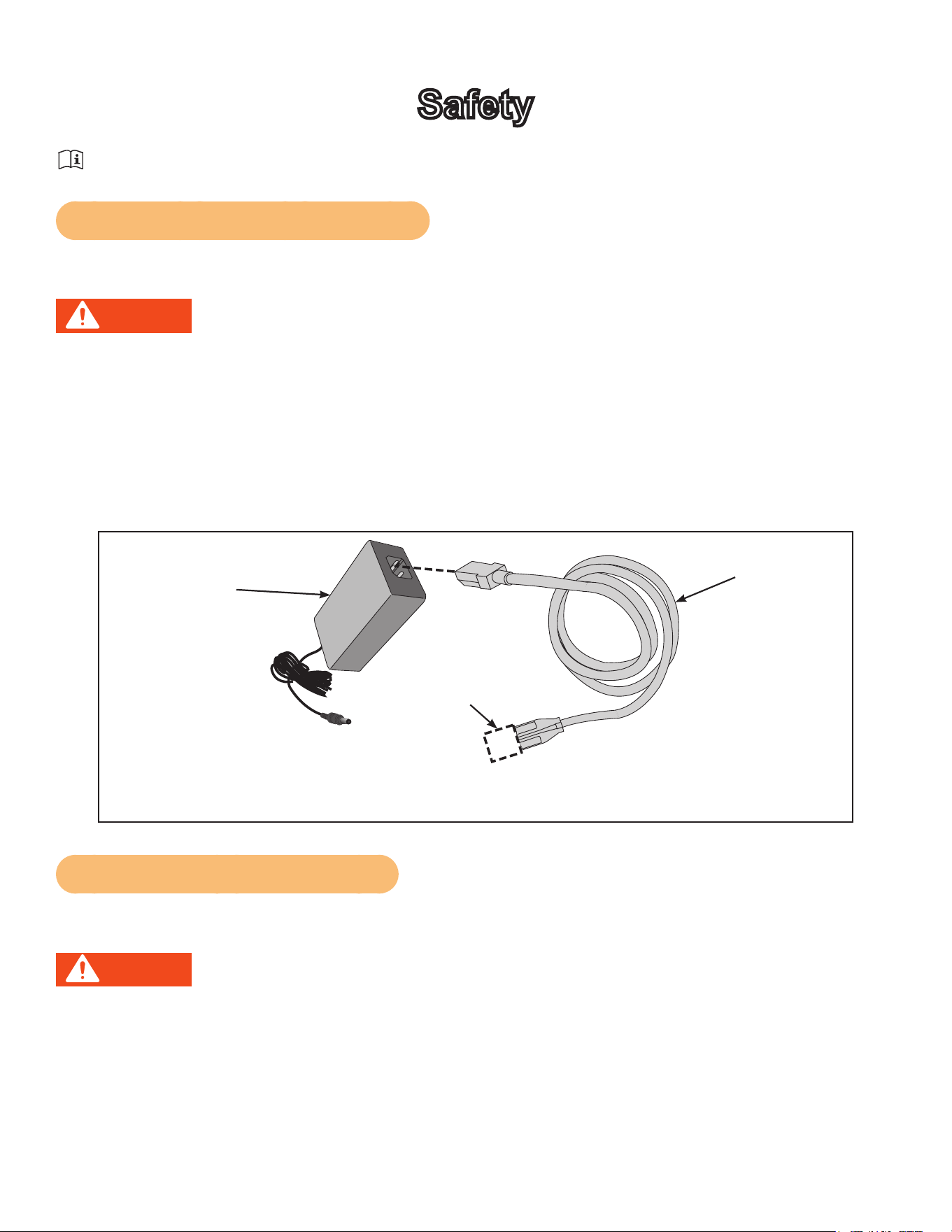
Ground and Voltage Information
AC Power Adapter is optional.
DANGER: Death or serious injury can occur. To avoid death or injury the following
precautions must be observed. Equipment must be properly grounded. Check
with a qualied electrician or service provider to verify the unit is properly
grounded. Improper connection of equipment grounding can result in electric
shock.
Cybexisnotresponsibleforinjuriesordamagesasaresultofcordorplugmodication.
• Verify voltage requirements of unit match local voltage requirements.
• Verify unit outlet is the same conguration as the plug.
Power
Adapter
Power Cord
Use Cybex supplied power adapter and power cords only.
Connector
Varies by
Country
Important Safety Instructions
(Save These Instructions)
DANGER: Death or serious injury can occur. To avoid death or injury the following
precautions must be observed. Always unplug this unit from the electrical
outlet before cleaning. Unplugging equipment reduces risk for shock.
User Safety Precautions
• KEEP ALL CHILDREN 12 AND UNDER AWAY! Teenagers or disabled must be supervised.
• Obtain a medical exam before beginning any exercise program.
• Stop exercising if feeling faint, dizzy, or experiencing pain and consult your physician.
• Obtain instruction before using.

Cybex Arc Trainer 625A/625AT Owner’s Manual
5
• Read and understand all warnings posted on the unit before using.
• Use the handrails for support and to maintain balance.
• Wait until foot plates come to a complete stop before dismounting.
• Keep foot plate surface clean and dry.
• DO NOT wear loose or dangling clothing while using.
• Keep all body parts and other items free and clear of moving parts.
• DO NOT use unit if user exceeds 400 lbs. (180 kg). This is the rated maximum user weight.
• Report any malfunctions, damage or repairs to the facility.
• Replace any warning labels if damaged, worn or illegible.
Facility Safety Precautions
It is the sole responsibility of the user/owner or facility operator to ensure that regular maintenance is
performed.
• Enforce all user and safety precautions.
• Read and understand the Owner’s Manual completely before assembling, servicing or using unit.
• Verify all users are properly trained on using the equipment.
• Do not use unit outdoors.
• Verify that each unit is setup, leveled and operated on a solid level surface. Do not install equipment
on an uneven surface.
• Verify there is enough room for safe access and operation of unit.
• Use Cybex AC power adapters only.
• Do not use the optional power adapter in damp or wet locations.
• Do not use the unit if: (1) the unit is plugged into an optional power adapter that has a damaged
cord; (2) the unit is not working properly or (3) if the unit has been dropped or damaged. Seek
service from a qualied technician.
• EQUIPMENT is not suitable for use in the presence of aerosol (spray), FLAMMABLE
ANAESTHETIC MIXTURE WITH AIR or WITH OXYGEN or NITROUS OXIDE.
• Perform regular maintenance checks on unit. Performance level can be maintained only if
examined regularly. Pay close attention to all areas most susceptible to wear, including (but not
limited to) cables, pulleys, belts and grips.
• Replace any warning labels if damaged, worn, or illegible.
• Immediately replace worn or damaged components. If unable to immediately replace worn or
damaged components, then remove unit from service until repair is made.
• Do not attempt electrical or mechanical repairs. Seek qualied repair personnel when servicing. If
you live in the USA, contact Cybex Customer Service at 888-462-9239. If you live outside the USA,
contact Cybex Customer Service at 508-533-4300.
• Use only Cybex supplied components to maintain/repair unit.
• Keep a repair log of all maintenance activities.
• Disconnect the optional power adapter before servicing unit.
• Do not use attachments unless recommended for the unit by Cybex.
• The unit may generate electromagnetic or other forms of interference, or it may be affected by
interference from other equipment nearby. If this is suspected, take precautions by separating the
equipment or otherwise shielding it to avoid such interference.
Cybex Arc Trainer 625A/625AT Owner’s Manual Cybex Arc Trainer 625A/625AT Owner’s Manual
6
Warning and Caution Decals
To replace any worn or damaged decals do one of the following: Visit www.cybexintl.com to shop
for parts online, fax orders to 508-533-5183 or contact Cybex Customer Service at 888-462-9239. If
you are located outside of the USA, call 508-533-4300. For location or part number of labels, see the
parts list and exploded-view diagram on the Cybex web site at www.cybexintl.com.
Warning decals indicate a potentially hazardous situation which, if not avoided, could result in death
or serious injury.
Carefully read and understand the following caution and warning labels before using the unit.
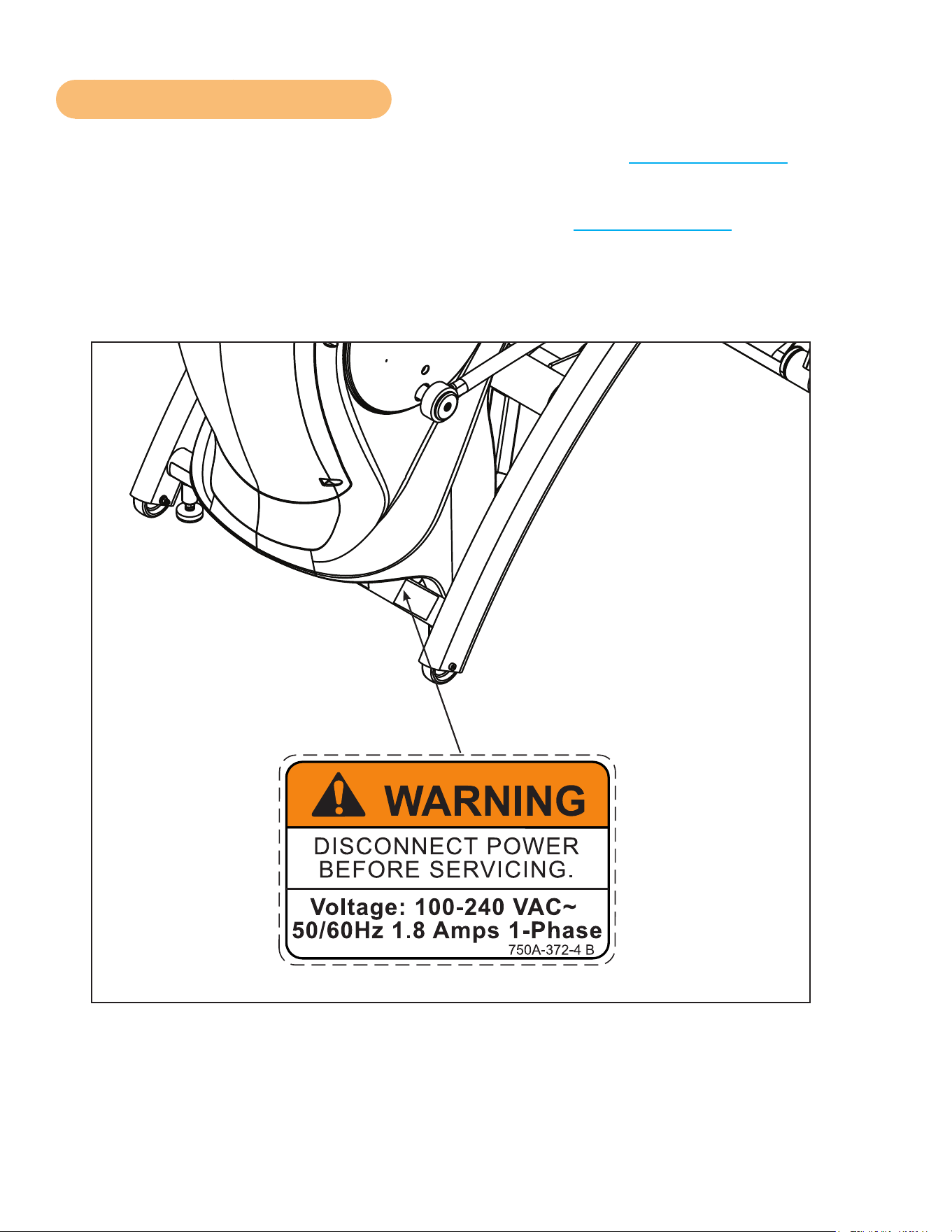
Warning decal part number
750A-372-4 (if applicable)
DECAL, DISCONNECT POWER
ENGLISH
REL
7-24-08
750A-372-4
125
1:1
OWATONNA
MFG. APPR.
TECH. PUBS. APPR. DAT E
DAT E
REV.
DWG. NO.
SCALE
SIZE
CHECKED BY
DWG. BY
TITLE:
FINISH:
MATERIAL:
B
SHEET
OF
EXCEPT AS NOTED
GENERAL
TOLERANCES:
2 DECIMALS ± .03
3 DECIMALS ± .015
ANGLES ± 1°
FEATURES SHOWN
PERPENDICULAR OR
PARALLEL SHALL BE
SO WITHIN ± 1°
REMOVE ALL BURRS
BREAK SHARP EDGES
.005/.010 R
SURFACE FINISH
INDICATED PER
ANSI B46.1-1985
GENERAL
MACHINING
DIMENSIONS
IN INCHES
DAT E
DAT E
REMOVE CARBURIZATION
AND SCALE FROM LASER
AND PLASMA CUT EDGES
ALL MATERIAL MUST COMPLY TO
EUROPEAN UNION DIRECTIVE
2002/95/EC RoHS (RESTRICTION
OF HAZARDOUS SUBSTANCES)
1 1
B
NOTE: SEE ENGINEERING DRAWING 750A-372-X FOR SPECIFICATIONS.
BB
8-13-08
EML
8-13-08
750A-372-4 B
WARNING
DISCONNECT POWER
BEFORE SERVICING.
Voltage: 100-240 VAC~
50/60Hz 1.8 Amps 1-Phase
2.00
1.25
R .10
4 PLACES
SAFETY ORANGE PMS 152
BLACK TRIANGLE W/ ORANGE
EXCLAMATION POINT, BLACK LETTERS
18 PT ARIAL BOLD FONT
PART NUMBER
6 PT ARIAL TEXT
WHITE BACKGROUND WITH
BLACK 10 PT ARIAL TEXT
WHITE BACKGROUND WITH
BLACK 10 PT ARIAL BOLD TEXT
Cybex Arc Trainer 625A/625AT Owner’s Manual
7
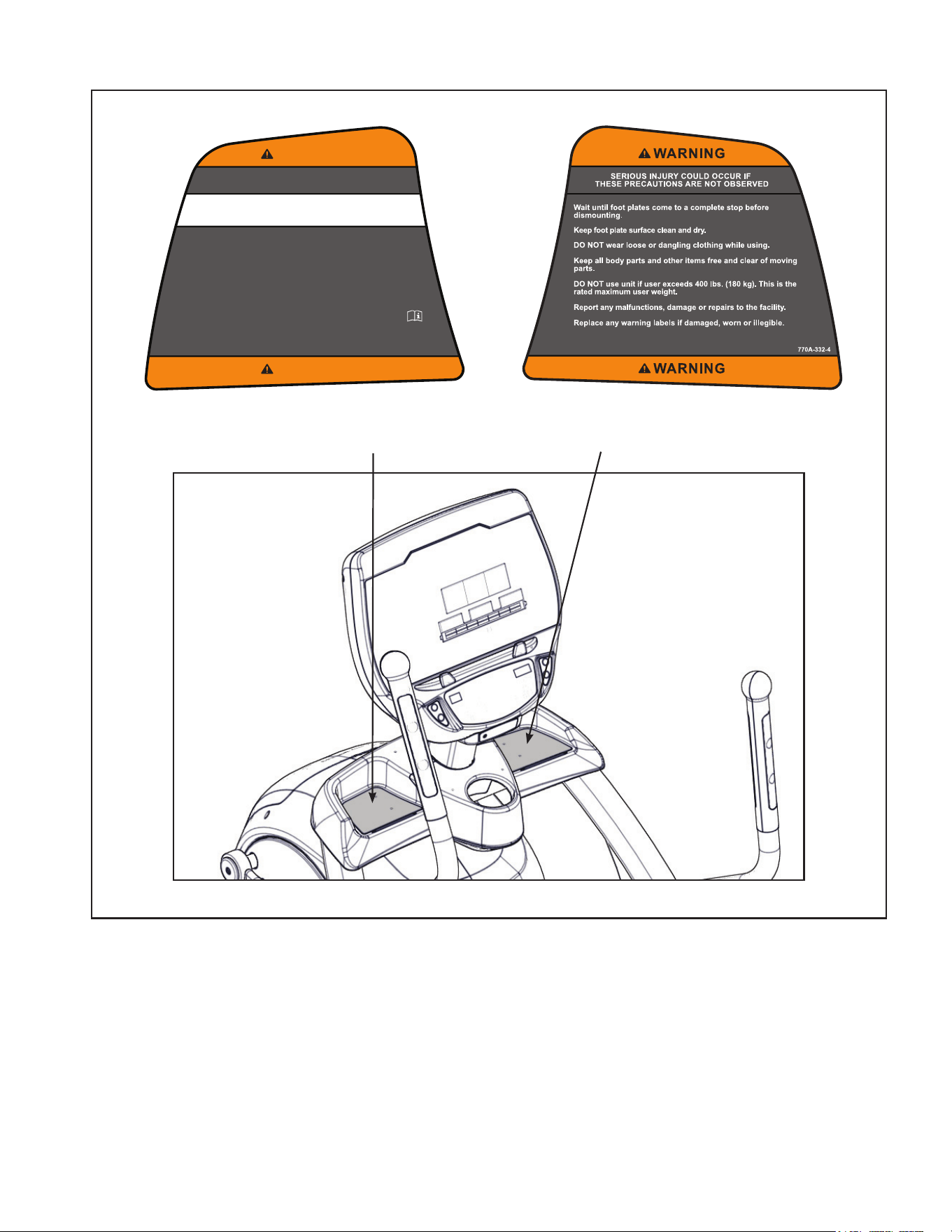
770A-331-4
SERIOUS INJURY COULD OCCUR IF
THESE PRECAUTIONS ARE NOT OBSERVED
WARNING
WARNING
KEEP ALL CHILDREN 12 AND UNDER AWAY! Teenagers or
disabled must be supervised.
Obtain a medical exam before beginning any exercise program.
Stop exercising if feeling faint, dizzy, or experiencing pain and
consult your physician.
Obtain instruction before using.
Read and understand the Owner's Manual and all warnings
posted on the unit before using.
Use the handrails for support and to maintain balance.
WARNING! Heart rate monitoring systems may be
inaccurate. Over exercise may result in serious injury or
death. If you feel faint stop exercising immediately.
Warning decal part
number 770A-331-4
625AT Shown
Warning decal part
number 770A-332-4
Cybex Arc Trainer 625A/625AT Owner’s Manual Cybex Arc Trainer 625A/625AT Owner’s Manual
8
125
1:1
OWATONNA
MFG. APPR.
TECH. PUBS. APPR. DATE
DATE
REV.
DWG. NO.
SCALE
SIZE
CHECKED BY
DWG. BY
TITLE:
FINISH:
MATERIAL:
B
SHEET
OF
EXCEPT AS NOTED
GENERAL
TOLERANCES:
2 DECIMALS ± .03
3 DECIMALS ± .015
ANGLES ± 1°
FEATURES SHOWN
PERPENDICULAR OR
PARALLEL SHALL BE
SO WITHIN ± 1°
REMOVE ALL BURRS
BREAK SHARP EDGES
.005/.010 R
SURFACE FINISH
INDICATED PER
ANSI B46.1-1985
GENERAL
MACHINING
DIMENSIONS
IN INCHES
DATE
DATE
REMOVE CARBURIZATION
AND SCALE FROM LASER
AND PLASMA CUT EDGES
ALL MATERIAL MUST COMPLY TO
EUROPEAN UNION DIRECTIVE
2002/95/EC RoHS (RESTRICTION
OF HAZARDOUS SUBSTANCES)
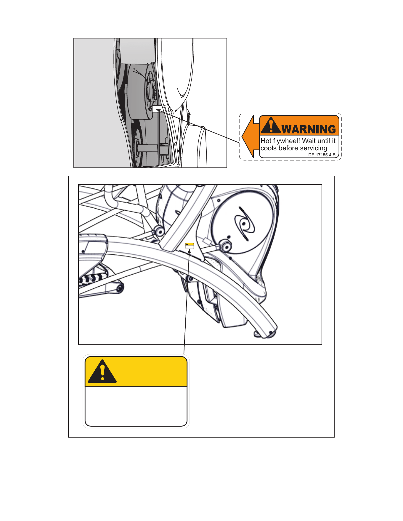
DE-17155-4
DECAL, WARNING
ENGLISH
1 1
B
JT
7-22-03
WARNING
DE-17155-4 B
Hot flywheel! Wait until it
cools before servicing.
SAFETY ORANGE PMS 152
BLACK TRIANGLE W/ ORANGE
EXCLAMATION POINT, BLACK LETTERS
17.54 PT ARIAL BLACK FONT
WHITE BACKGROUND WITH
BLACK 10.5 PT ARIAL TEXT
PART NUMBER
6.5 PT ARIAL TEXT
Warning decal part
number DE-17155-4
125
1:1
OWATONNA
MFG. APPR.
TECH. PUBS. APPR. DATE
DATE
REV.
DWG. NO.
SCALE
SIZE
CHECKED BY
DWG. BY
TITLE:
FINISH:
MATERIAL:
B
SHEET
OF
EXCEPT AS NOTED
GENERAL
TOLERANCES:
2 DECIMALS ± .03
3 DECIMALS ± .015
ANGLES ± 1°
FEATURES SHOWN
PERPENDICULAR OR
PARALLEL SHALL BE
SO WITHIN ± 1°
REMOVE ALL BURRS
BREAK SHARP EDGES
.005/.010 R
SURFACE FINISH
INDICATED PER
ANSI B46.1-1985
GENERAL
MACHINING
DIMENSIONS
IN INCHES
DATE
DATE
REMOVE CARBURIZATION
AND SCALE FROM LASER
AND PLASMA CUT EDGES
ALL MATERIAL MUST COMPLY TO
EUROPEAN UNION DIRECTIVE
2002/95/EC RoHS (RESTRICTION
OF HAZARDOUS SUBSTANCES)
DECAL, CAUTION MOVING PARTS
DE-17219-4
B
1 1
JT
7-22-03
1.80
1.25
R .12
4 PLACES
SAFETY YELLOW PMS 108
BACKGROUND BLACK TRIANGLE
W/ YELLOW EXCLAMATION POINT,
BLACK LETTERS 18.9 PT ARIAL BLACK FONT
WHITE BACKGROUND WITH
BLACK 12 PT ARIAL TEXT
PART NUMBER
6.5 PT ARIAL TEXT
DE-17219-4 B
CAUTION
Moving parts.
Keep hands away
when in use.
DE-17219-4 B
CAUTION
Moving parts.
Keep hands away
when in use.
(SPECS)
MASTER
ARTWORK
DE-17219-4 A
CAUTION
Moving parts.
Keep hands away
when in use.
Caution decal part
number DE-17219-4
(Both Sides)
125
1:1
OWATONNA
MFG. APPR.
TECH. PUBS. APPR. DATE
DATE
REV.
DWG. NO.
SCALE
SIZE
CHECKED BY
DWG. BY
TITLE:
FINISH:
MATERIAL:
B
SHEET
OF
EXCEPT AS NOTED
GENERAL
TOLERANCES:
2 DECIMALS ± .03
3 DECIMALS ± .015
ANGLES ± 1°
FEATURES SHOWN
PERPENDICULAR OR
PARALLEL SHALL BE
SO WITHIN ± 1°
REMOVE ALL BURRS
BREAK SHARP EDGES
.005/.010 R
SURFACE FINISH
INDICATED PER
ANSI B46.1-1985
GENERAL
MACHINING
DIMENSIONS
IN INCHES
DATE
DATE
REMOVE CARBURIZATION
AND SCALE FROM LASER
AND PLASMA CUT EDGES
ALL MATERIAL MUST COMPLY TO
EUROPEAN UNION DIRECTIVE
2002/95/EC RoHS (RESTRICTION
OF HAZARDOUS SUBSTANCES)
DECAL, CAUTION MOVING PARTS
DE-17219-4 B
1 1
JT
7-22-03
1
.80
1
.25
R .12
4 PLACES
SAFETY YELLOW PMS 108
BACKGROUND BLACK TRIANGLE
W/ YELLOW EXCLAMATION POINT,
BLACK LETTERS 18.9 PT ARIAL BLACK FONT
WHITE BACKGROUND WITH
BLACK 12 PT ARIAL TEXT
PART NUMBER
6.5 PT ARIAL TEXT
DE-17219-4 B
CAUTION
Moving parts.
Keep hands away
when in use.
DE-17219-4 B
CAUTION
Moving parts.
Keep hands away
when in use.
(SPECS)
MASTER
ARTWORK
DE-17219-4 A
CAUTION
Moving parts.
Keep hands away
when in use.
Cybex Arc Trainer 625A/625AT Owner’s Manual
9
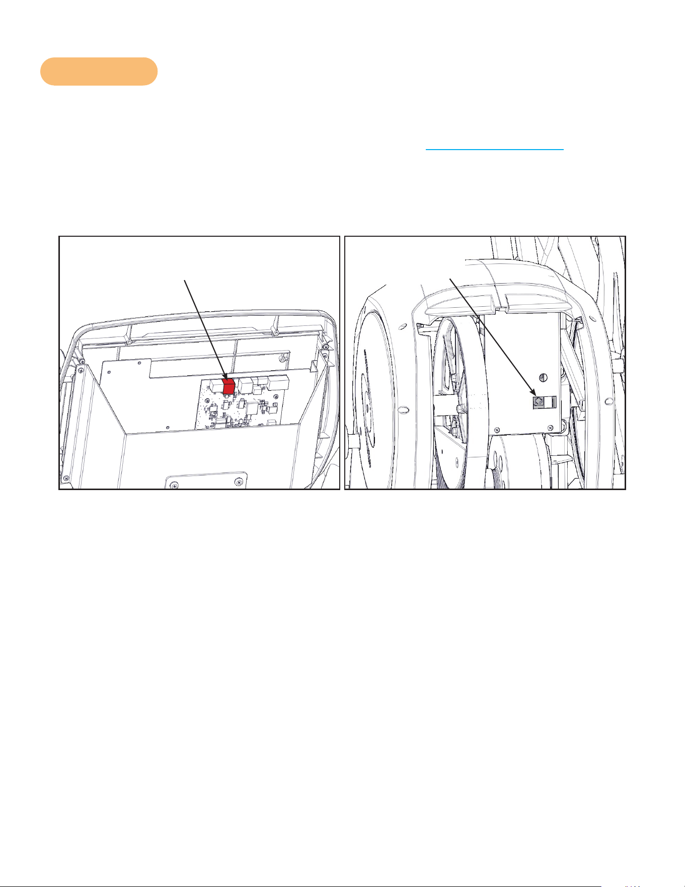
CSAFE Port
The CSAFE standard denes a communication protocol and low-voltage DC power source specic
to the Fitness Equipment Industry. These RJ-45 phone jacks are provided for use ONLY within the
CSAFE protocol. For more information on CSAFE standard, visit www.tlinxx.com/csafe.
The CSAFE port inside the console, accessible through the back cover, is the only port that carries
BOTH the CSAFE communication lines and the 9.0v DC CSAFE power supply. If attaching a CSAFE
compliant device that requires power, this connection must be used. Power is present only when the
unit is in use or when a power supply is attached.
CSAFE Port Display Board
(Red Port)
CSAFE Port
Lower Board

Cybex Arc Trainer 625A/625AT Owner’s Manual Cybex Arc Trainer 625A/625AT Owner’s Manual
10
Assembly
Specifications - 625A
Classification S (Studio)
Accuracy A
Assembled
Length
75.75” (192 cm)
Assembled
Width
32” (81 cm)
Height: 62.5” (159 cm)
Weight of
Product
404 lbs (183 kg)
Shipping
Weight
429 lbs (195 kg)
Incline Levels 0-20
Resistance
Levels
0-100
Stride Length 24” (61 cm) xed length.
Programs Quick Start plus Manual, and nine Factory Programs.
Console
Features
Upper console: LED or EPEM (Embedded Personal Entertainment Monitor).
Displays Cal/Hr, Distance, Strides per Minute, Calories, Watts, METs and BPM.
Lower console: Two numeric displays for incline, resistance and level. Accessory
trays and water bottle holder
Heart Rate
Features
Built-in wireless heart rate receiver (transmitter not included) and contact heart rate
monitoring.
Frame Colors
Standard: White Texture, Black Texture, Metaltone Gold, Black Chrome, Platinum
Sparkle.
Custom: Unlimited colors available.
Resistance
Range
0-900 watt.
Maximum
User Weight
400 lbs. (181 kg).
Power Rating Self powered or 100 - 240 VAC~, 50/60 Hz, 1.8A, 1-phase.
Options AC Power Adapter
The dimensions stated in the installation instructions are the recommended minimum dimensions as
set forth by the manufacturer. The actual area for access and passage shall be the responsibility of
the facility and should take into account any required local codes or regulations.
Cybex Arc Trainer 625A/625AT Owner’s Manual
11
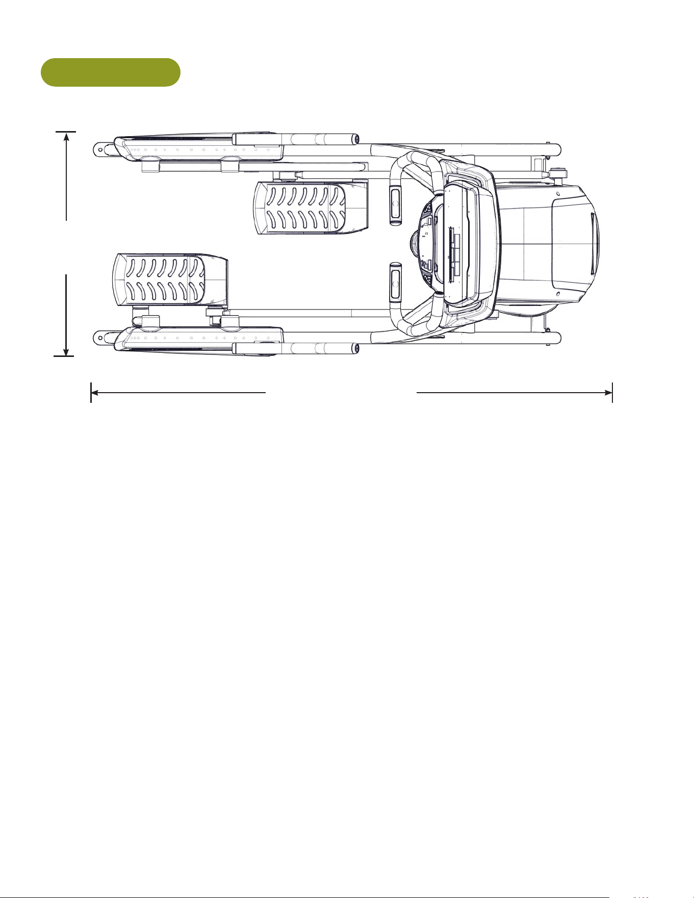
625A Top View
32”
(81 cm)
75.75” (192 cm)

Cybex Arc Trainer 625A/625AT Owner’s Manual Cybex Arc Trainer 625A/625AT Owner’s Manual
12
Specifications - 625AT
Classification S (Studio)
Accuracy A
Assembled
Length
75.75” (192 cm)
Assembled
Width
32” (81 cm)
Height: 62.5”(159 cm)
Weight of
Product
412 lbs. (187 kg.)
Shipping
Weight
437 lbs. (198 kg.)
Incline Levels 0-20
Resistance
Levels
0-100
Stride Length 24” (61 cm) xed length.
Programs Quick Start plus Manual, and nine Factory Programs.
Console
Features
Upper console: LED or EPEM (Embedded Personal Entertainment Monitor).
Displays Cal/Hr, Distance, Strides per Minute, Calories, Watts, METs and BPM.
Lower console: Two numeric displays for incline, resistance and level. Accessory
trays and water bottle holder.
Heart Rate
Features
Built-in wireless heart rate receiver (transmitter not included) and contact heart rate
monitoring.
Frame Colors
Standard: White Texture, Black Texture, Metaltone Gold, Black Chrome, Platinum
Sparkle.
Custom: Unlimited colors available.
Resistance
Range
0-900 watt.
Maximum
User Weight
400 lbs. (181 kg).
Power Rating Self powered or 100 - 240 VAC~, 50/60 Hz, 1.8A, 1-phase.
Options AC Power Adapter
The dimensions stated in the installation instructions are the recommended minimum dimensions as
set forth by the manufacturer. The actual area for access and passage shall be the responsibility of
the facility and should take into account any required local codes or regulations.
Cybex Arc Trainer 625A/625AT Owner’s Manual
13
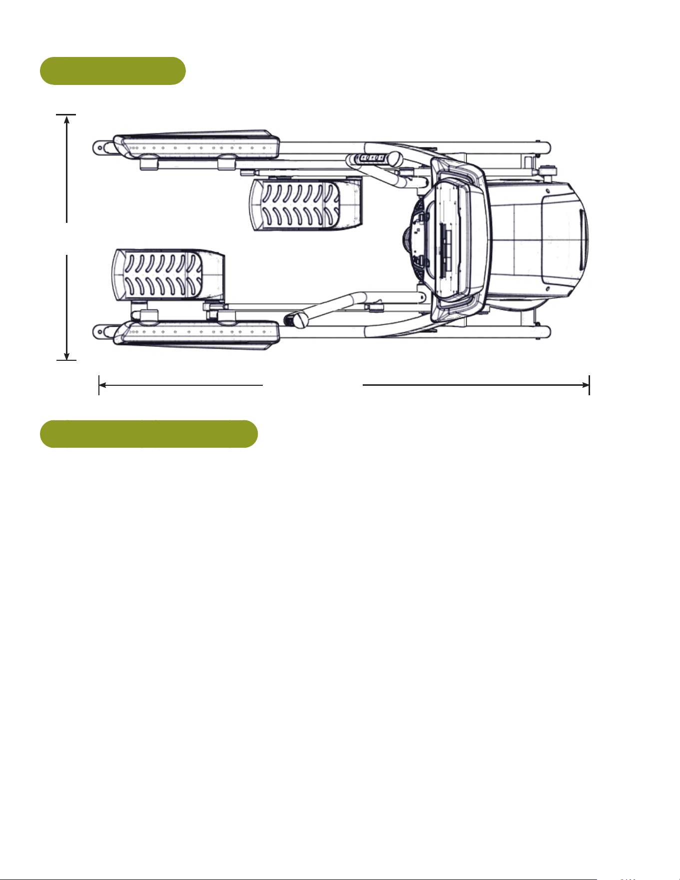
625AT Top View
32”
(81 cm)
75.75” (192 cm)
Environment and Storage
Humidity and Static Electricity
The unit is designed to function normally in an environment with a relative humidity range of 30% to
75%. The unit can be shipped and stored in a relative humidity range of 10% to 90%.
Dry air may cause static electricity. During workout, user may experience a shock due to build-up
of static electricity on the body and the discharge path of the unit. If static electricity is experienced,
increase humidity to a comfortable level through the use of a humidier.
Do not install, use, or store the unit in an area of high humidity, such as in the vicinity of a steam
room, sauna, indoor pool or outdoors. Exposure to extensive water vapor, chlorine and/or bromine
could adversely affect the electronics as well as other parts of the unit.
Temperature
The unit is designed to function normally in an environment with an ambient temperature range of 50°
F (10° C) to 104° F (40° C). The unit can be shipped and stored in an environment with an ambient
temperature range of 32° F (0° C) to 140° F (60° C).

Cybex Arc Trainer 625A/625AT Owner’s Manual Cybex Arc Trainer 625A/625AT Owner’s Manual
14
Warning and Caution Decals
Read and understand all warnings and cautions listed in Safety Section before assembling unit.
CAUTION: Serious injury or damage to machine can occur. To avoid injury the following
precautions must be observed. A minimum of two people are required to lift,
move and assemble this unit. Always use proper lifting methods when moving
heavy items.
Ensure all electrical requirements are met as indicated in the specications in the Safety Section and
as listed in this chapter.
Choosing and Preparing Site
Before assembling the unit, verify chosen site meets the following criteria:
• Area is well lit and well ventilated.
• Surface is structurally sound and properly leveled.
Place a 3/4” (1.9 cm) thick wood base under unit to protect carpeting.
Area allows for ample access and passage clearance around unit or for emergency dismount.
Minimum clearance is 19.7 inches (0.5 meters) on at least one side of unit and also behind unit.
Minimum clearance fo 12” (30 cm) between units for proper wireless heart rate signal operation.
Electrical Power Requirements
AC Power Adapter is optional.
• Verify unit is connected to an outlet having the same conguration as the plug.
• Verify connection is a grounded circuit.
• Do not use a ground-plug adapter to adapt the 3-prong power cord to a non-grounded electrical
outlet.
• Use Cybex supplied optional AC power kit only. Consult an electrician with any questions.
• Ensure outlets used by this product meet all local and federal building codes.

Cybex Arc Trainer 625A/625AT Owner’s Manual
15
625A Assembly
The words “left” and “right” denote the user’s orientation.
Read and understand all instructions thoroughly before assembling this unit. Check all items
carefully. If there is damage, see the Customer Service section of this manual for proper procedure to
return, replace, or reorder parts.
Verifycorrectpackage.
1. Read box label to verify the model number and voltage (optional) match what was ordered.
2. Lift and remove cardboard sleeve surrounding unit.
3. Verify paint color matches what was ordered.
Tools Required
• Phillips screwdriver
• Stubby Phillips screwdriver
• 7/32” Allen wrench (supplied)
• 9/16” Open end wrench (2)
Two people will be required for this procedure. It is the responsibility of the facility owner/owner of the
equipment to ensure that there is appropriate clearance around each machine to allow for safe use
and passage.
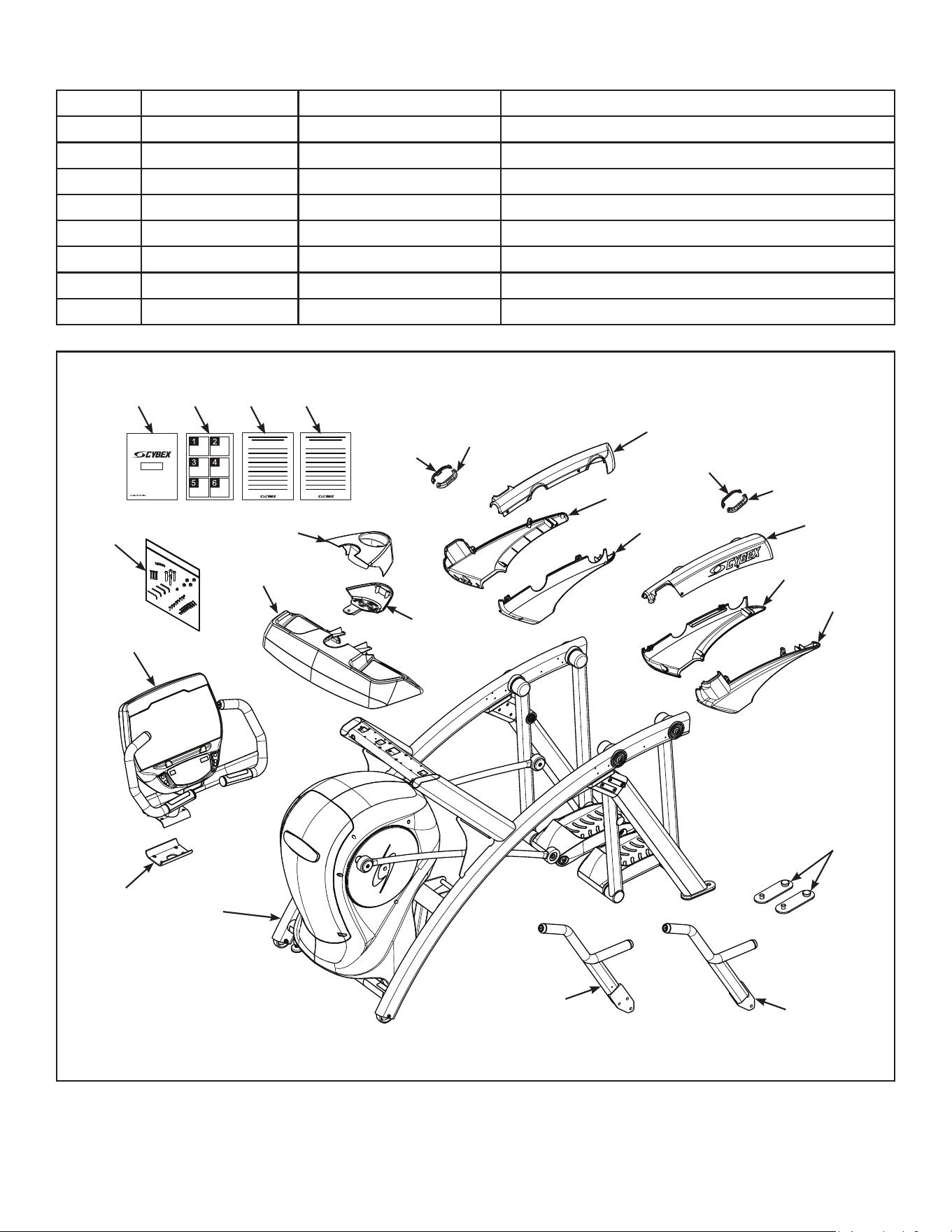
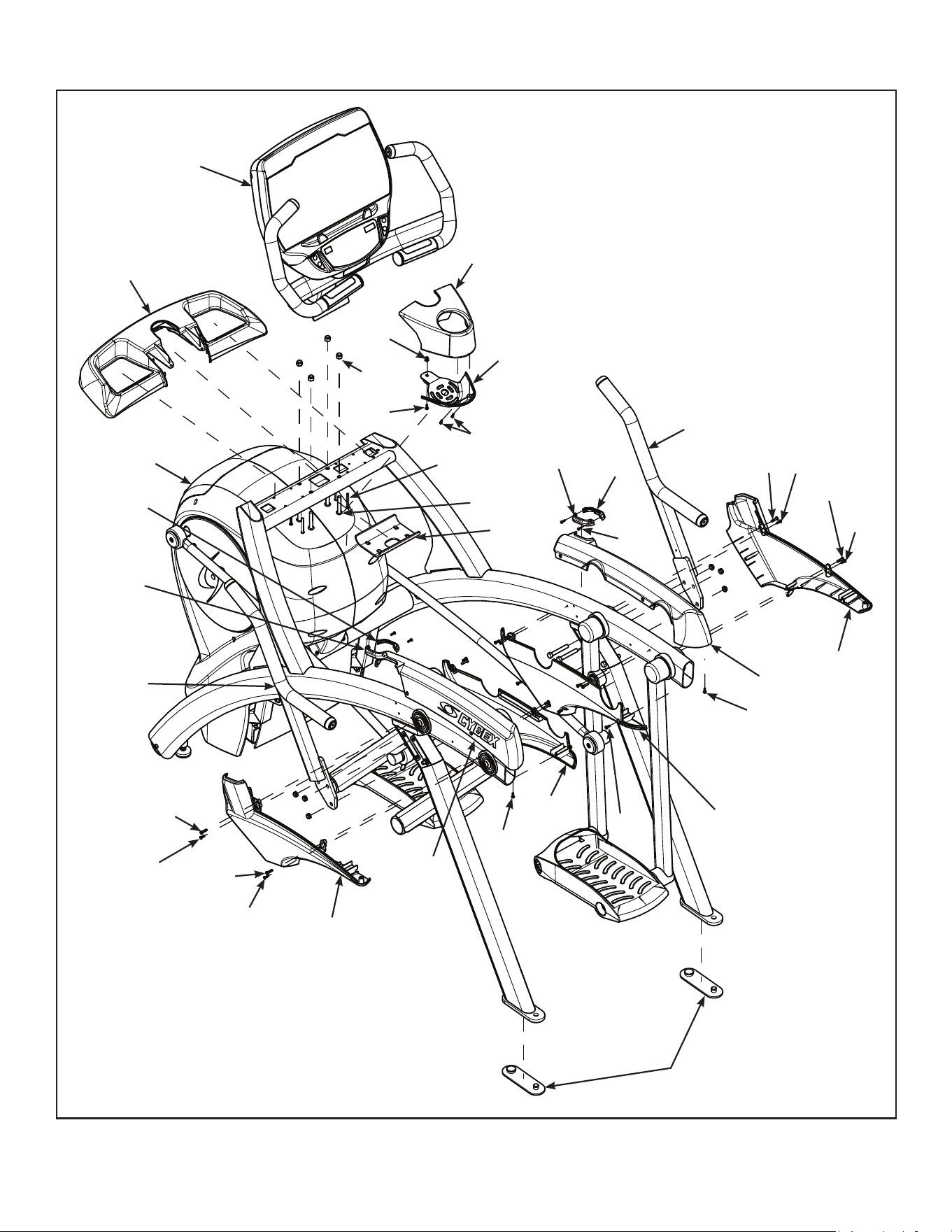
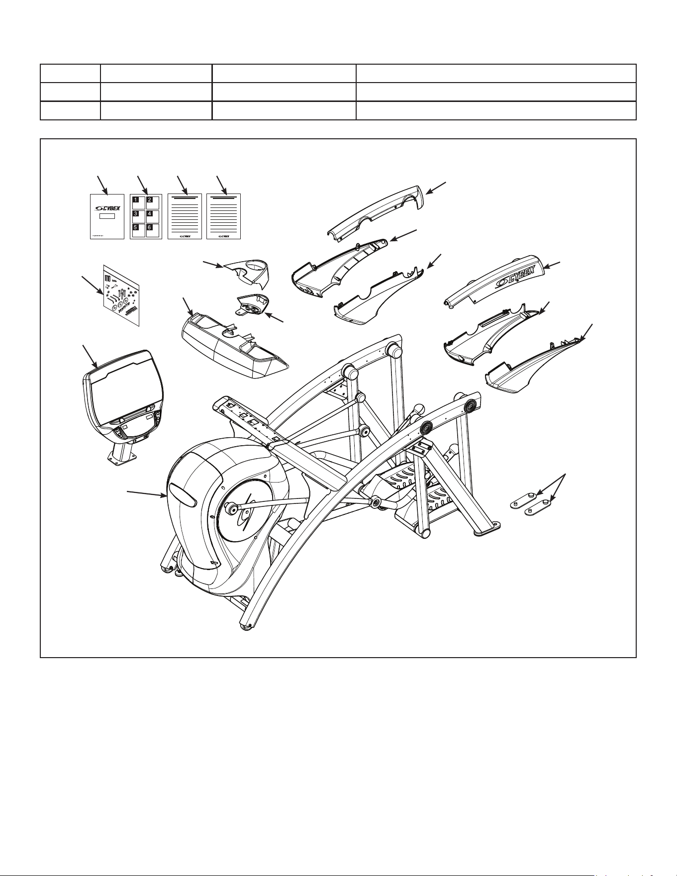
Unpack and verify contents of carton
See content listing and diagram below for carton contents. See Customer Service for contact
information if any parts are missing.
Item Quantity Part Number Description
1 1 Varies Base with covers attached
2 1 Varies Console assembly
3 2 12090-322 Foot pad
4 1 NA Handle, Right
5 1 NA Handle, Left
6 1 770A-316 Base, Accessory tray
7 1 770A-317 Cover, Top, Accessory tray
8 1 770A-318 Cover, Bottom, Accessory tray
9 1 770A-322 Cover, Rear, Top, Right
10 1 770A-323 Cover, Rear, Outer, Right
11 1 770A-324 Cover, Rear, Inner, Right
12 1 770A-319 Cover, Rear, Top, Left
13 1 770A-321 Cover, Rear, Inner, Left
14 1 770A-320 Cover, Rear, Outer, Left
15 1 770A-341 Collar, Outer, Right
16 1 770A-340 Collar, Inner, Right
Cybex Arc Trainer 625A/625AT Owner’s Manual Cybex Arc Trainer 625A/625AT Owner’s Manual
16
Item Quantity Part Number Description
17 1 770A-335 Collar, Inner, Left
18 1 770A-334 Collar, Outer, Left
19 1 NA Hardware pack
20 1 5625-4 Owner’s Manual
21 1 625A-328 Assembly poster
22 1 625A-330 Commercial Arc warranty sheet
23 1 625A-331 Consumer Arc warranty sheet
24 1 770A-310 Bracket, Lower, Display mount
#9
#10
#15
#13
#17
#11
#16
#14
#18
#12
#7
#2
#3
#6
#4
#5
#19
#20 #21 #22 #23
#24
#1
#8
Cybex Arc Trainer 625A/625AT Owner’s Manual
17
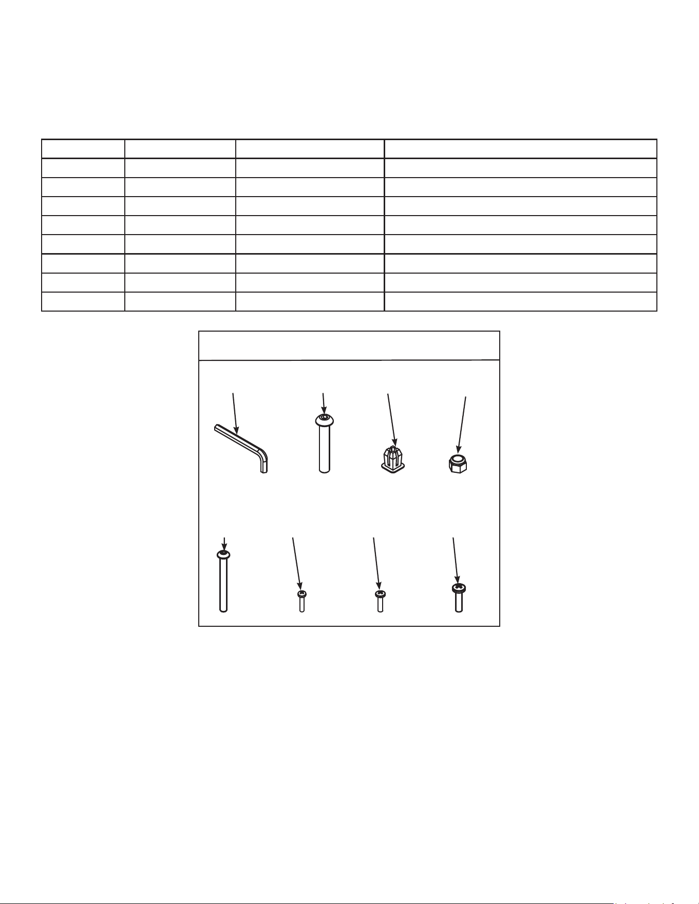
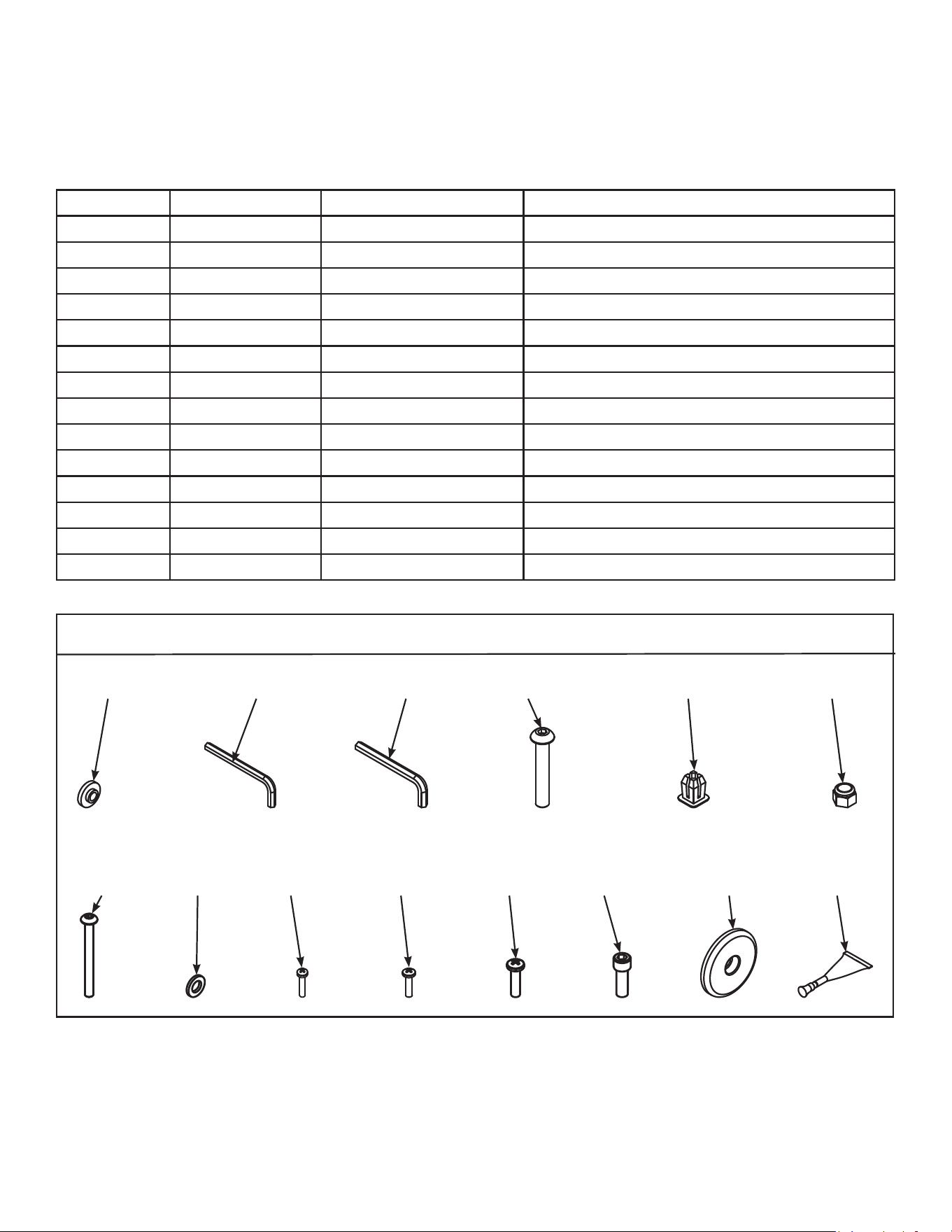
Verify contents of hardware pack
See hardware pack listings and hardware pack contents. See Customer Service for contact
information if any parts are missing.
Item Quantity Part Number Description
25 1 BK030204 7/32” Allen Wrench
26 4 HC700430 BHSCS .375-16 x 2.50”
27 1 HF540200 Grommet, Nylon
28 4 HN704901 Locknut, .375-16 Nylon
29 4 HT592526 Tap Sc 10-12 x 2.00 Pn Hd Phil
30 6 HT532512 Screw, Pan Head Phillips, #6 x .50”
31 19 HT552512 Screw, Pan Head Phillips, 8-16 x .50”
32 8 HT572515 Screw, Pan Head Phillips, 10-24 x .75”
625A Hardware
#28
#25
#29
#26
#30
#27
#31 #32
Cybex Arc Trainer 625A/625AT Owner’s Manual Cybex Arc Trainer 625A/625AT Owner’s Manual
18
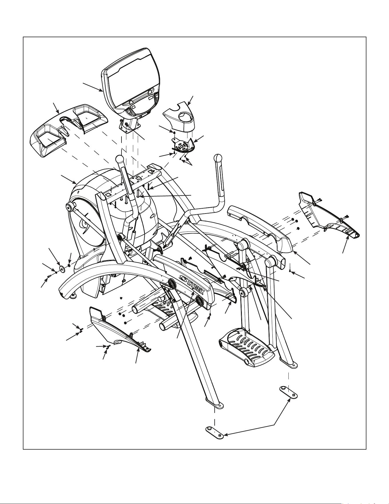
#9
#10
#15
#13
#17
#11
#16
#14
#18
#31
#30
#27
#24
#33
#32
#33
#32
#32
#34
#32
#31
#29
#28
#32
#12
#7
#2
#3
#6
#4
#33
#32
#33
#32
#5
#1
#8
Cybex Arc Trainer 625A/625AT Owner’s Manual
19
Lift and move unit
1. Remove large bolts and shipping supports. Keep package material on linkage arms at this
time. This will protect the paint from scratching during assembly.
2. Grasp each rear support leg rmly and lift with one person on each side.
3. Lift the lower rear support legs using proper lifting methods so the front transport wheels are
able to roll on floor.
4. Move unit to intended location.
5. Lower rear support legs.
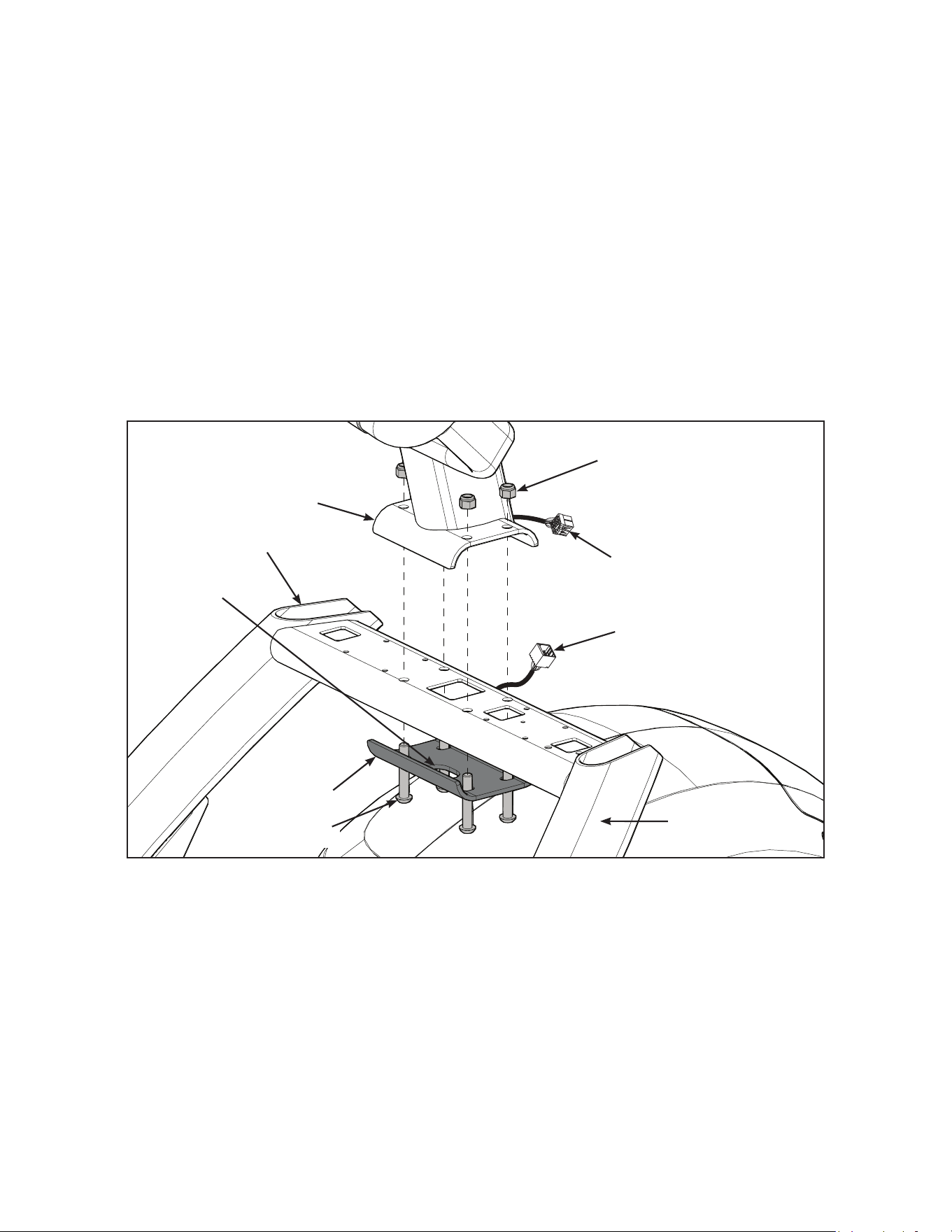
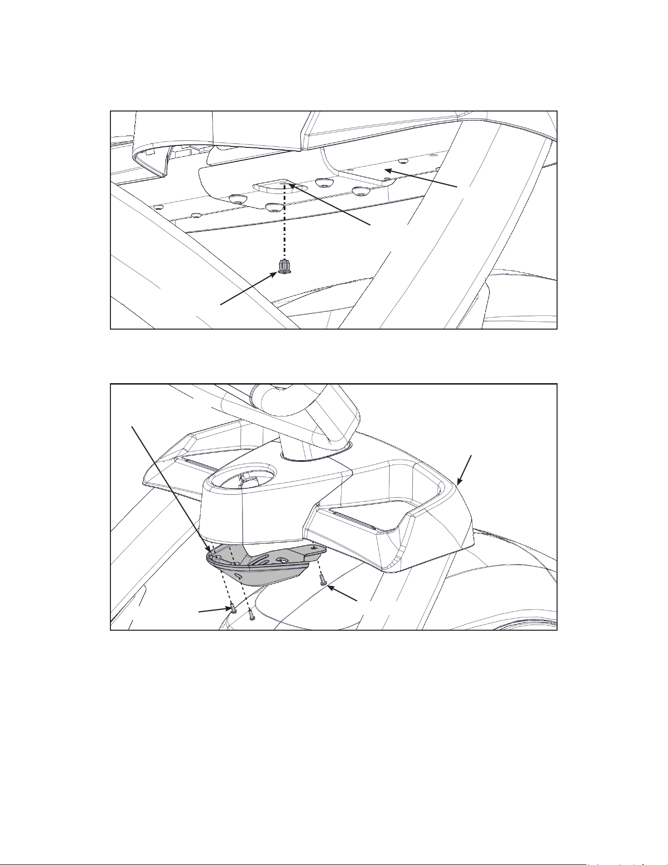
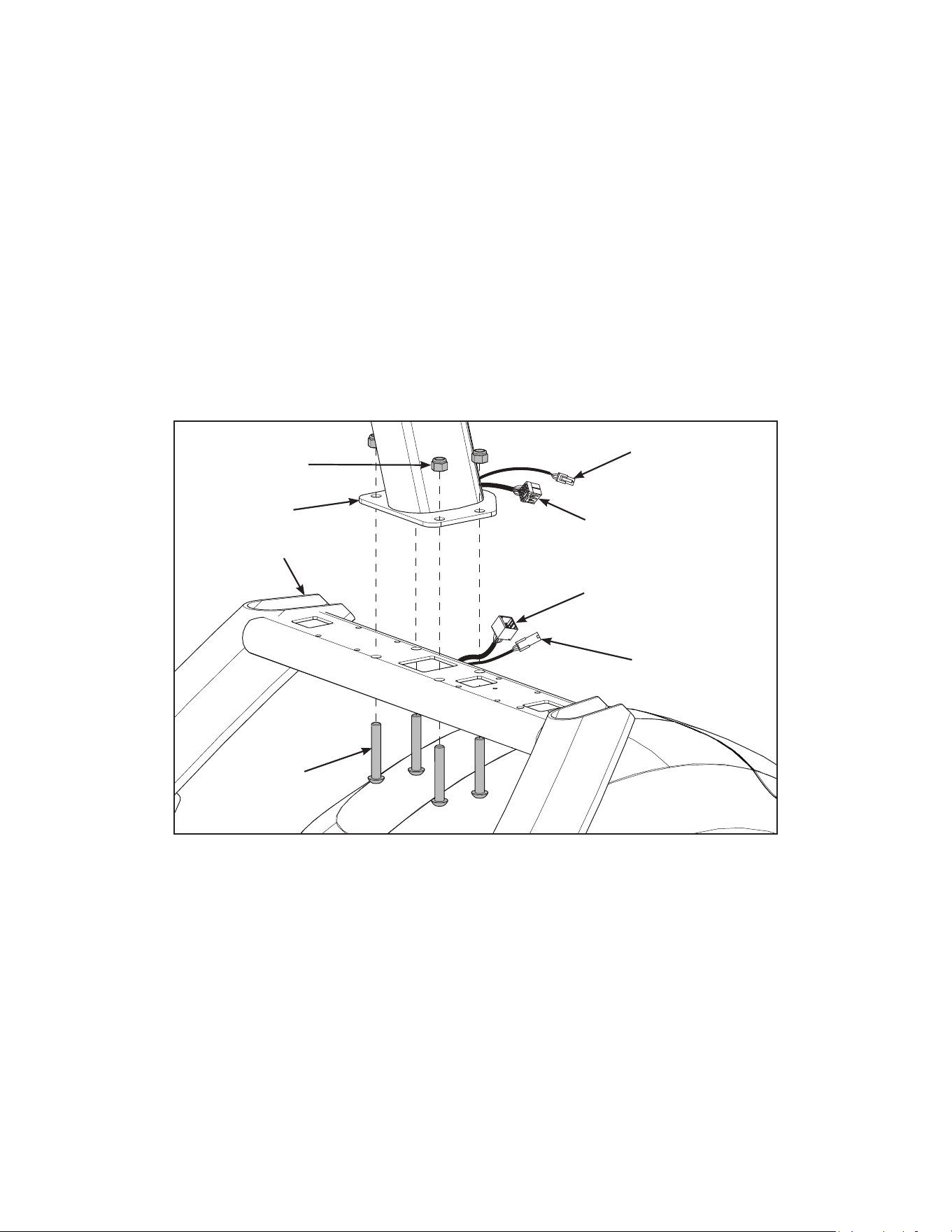
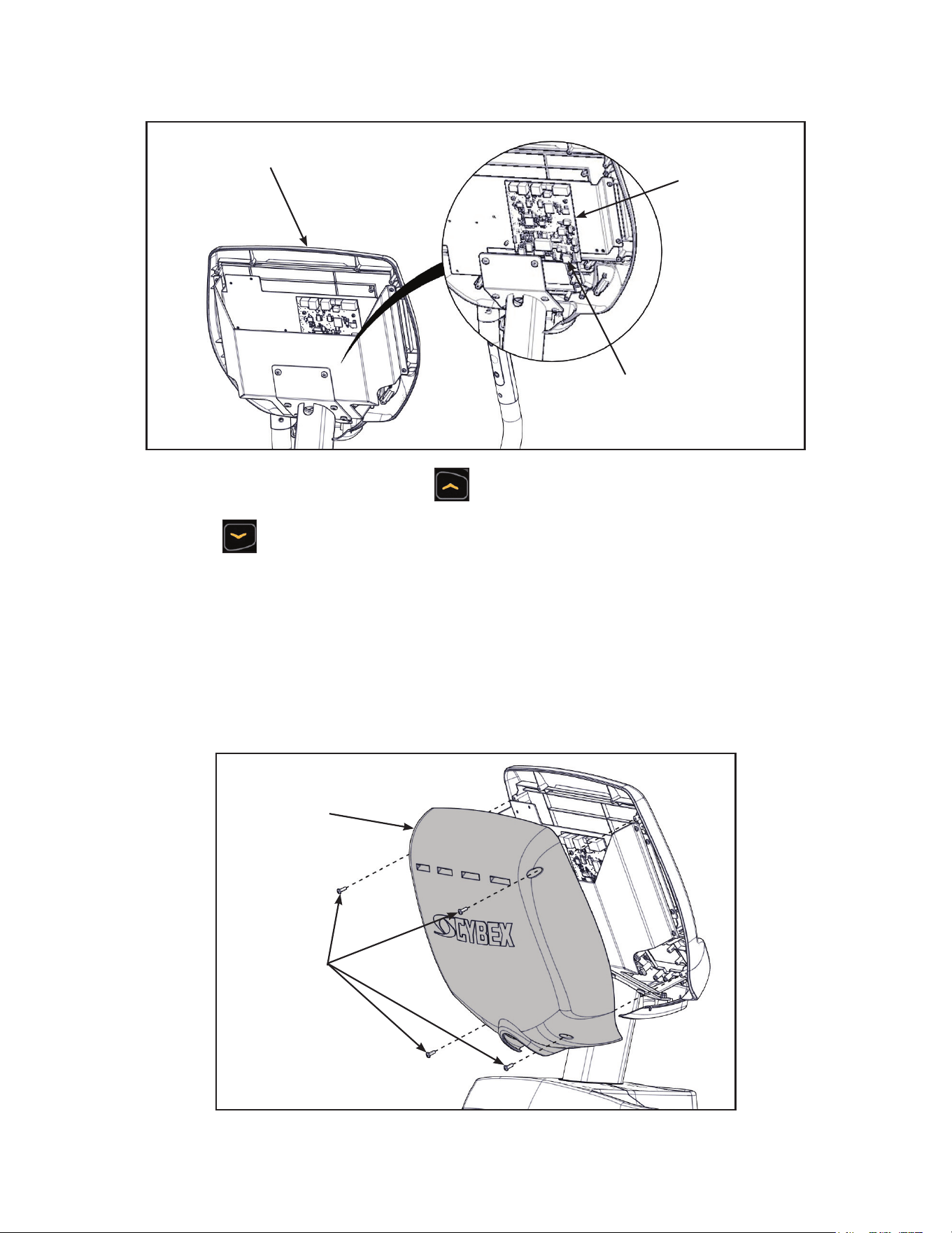
Attach 625A console assembly
1. Place the console into position on the frame. Do not pinch cables while lowering the console.
Upper Display
Cable
Console
Locknuts (4)
Bolts (4)
Lower
Bracket
Rear of Unit
Lower
Bracket
Hole
Frame
Lower Display
Cable
2. Insert (from underneath) the lower bracket and four bolts into the frame and console. Position
lower bracket with lower bracket hole towards the rear of unit.
3. Thread the four locknuts onto the bolts by hand.
4. Tighten the four bolts and locknuts with a 7/32” Allen wrench and a 9/16” open-end wrench.
5. Plug the upper display cable into the lower display cable.
Cybex Arc Trainer 625A/625AT Owner’s Manual Cybex Arc Trainer 625A/625AT Owner’s Manual
20
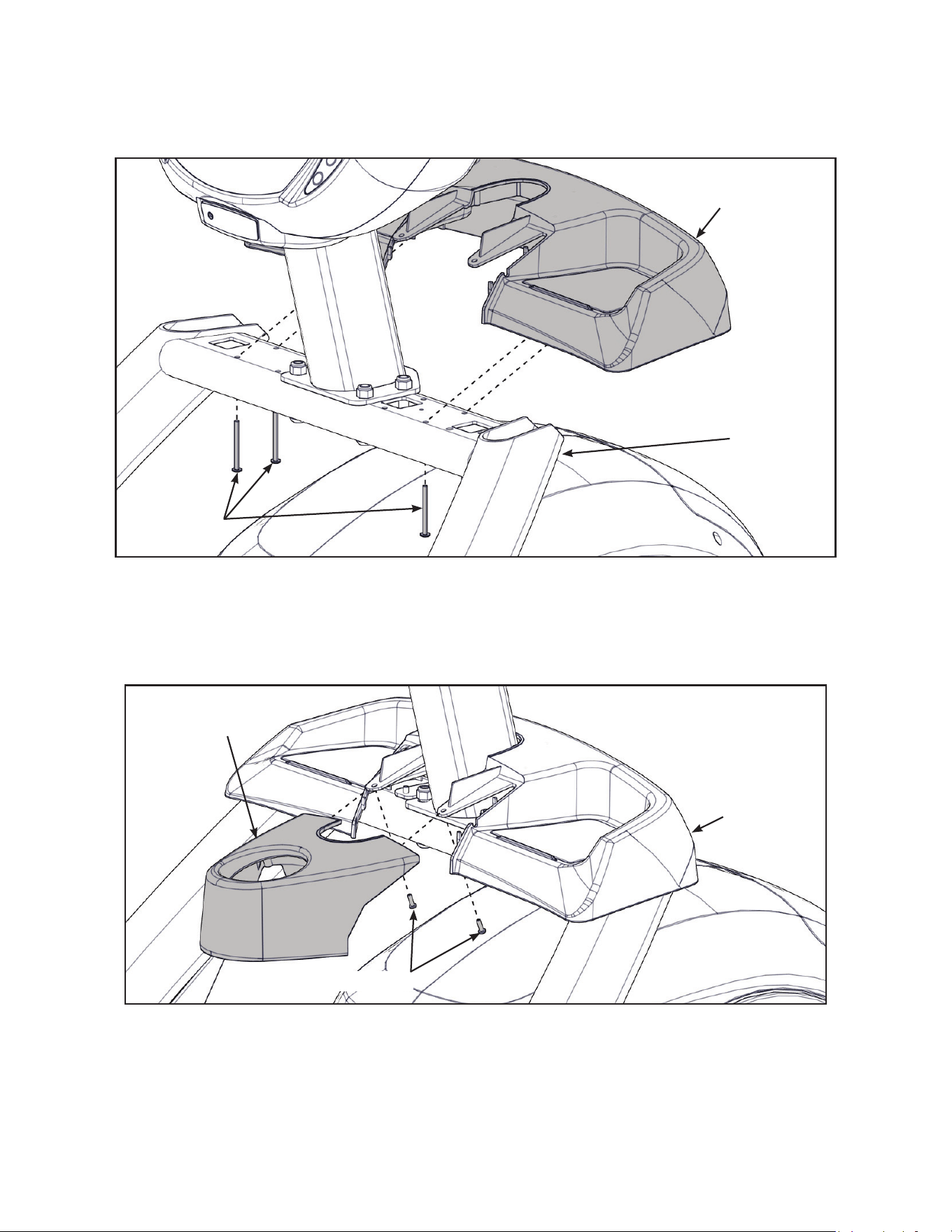
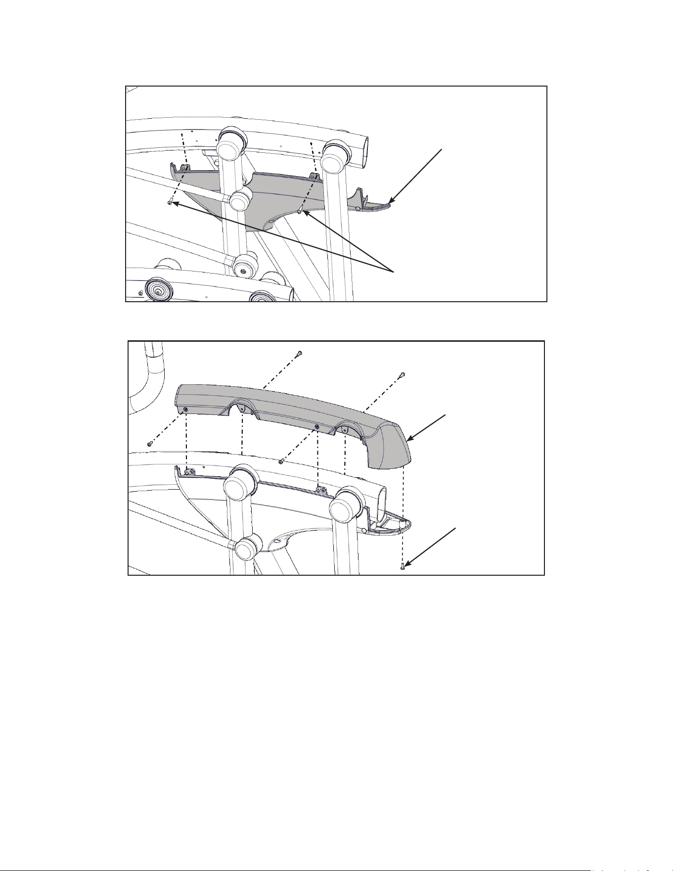
Install accessory tray base
1. Place the accessory tray base in position on the frame.
Screws (4)
Frame
Accessory
Tray Base
2. Install the four screws using a stubby Phillips screwdriver.
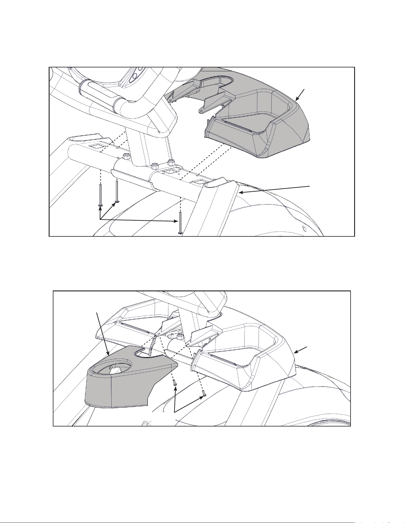
Install accessory tray top
1. Place the accessory tray top in position on the accessory tray base.
Screws (2)
Accessory
Tray Top
Accessory
Tray Base
2. Install the two screws using a stubby Phillips screwdriver.
Cybex Arc Trainer 625A/625AT Owner’s Manual
21
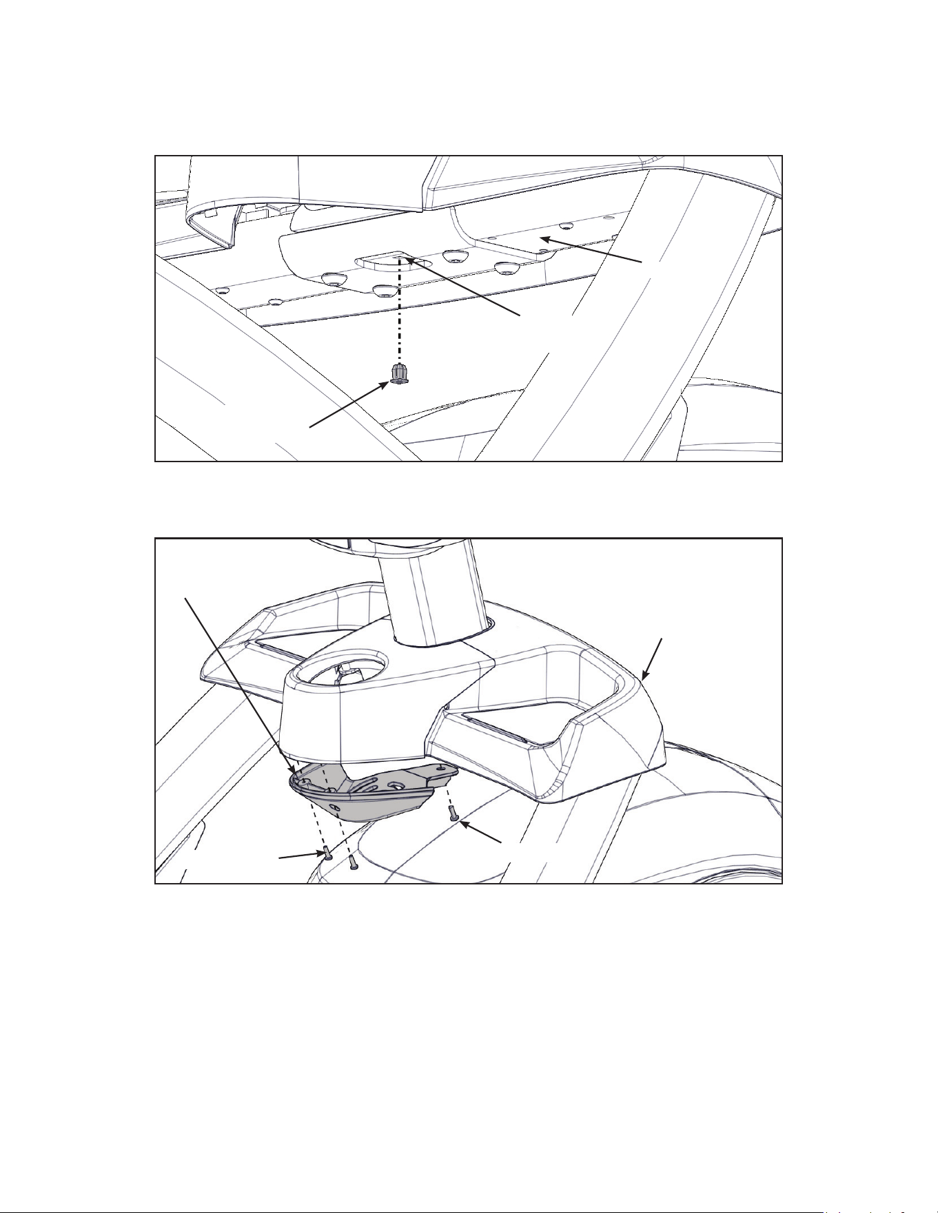
Install accessory tray bottom
1. Install the nylon grommet into the square hole in the frame.
Square
Hole
Frame
Nylon
Grommet
2. Install the accessory tray bottom to the accessory tray base with three screws using a Phillips
screwdriver.
Screws (2)
Screw
Accessory
Tray Base
Accessory
Tray Bottom
Cybex Arc Trainer 625A/625AT Owner’s Manual Cybex Arc Trainer 625A/625AT Owner’s Manual
22
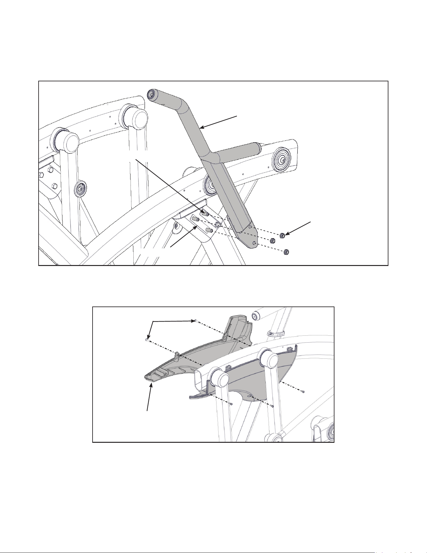
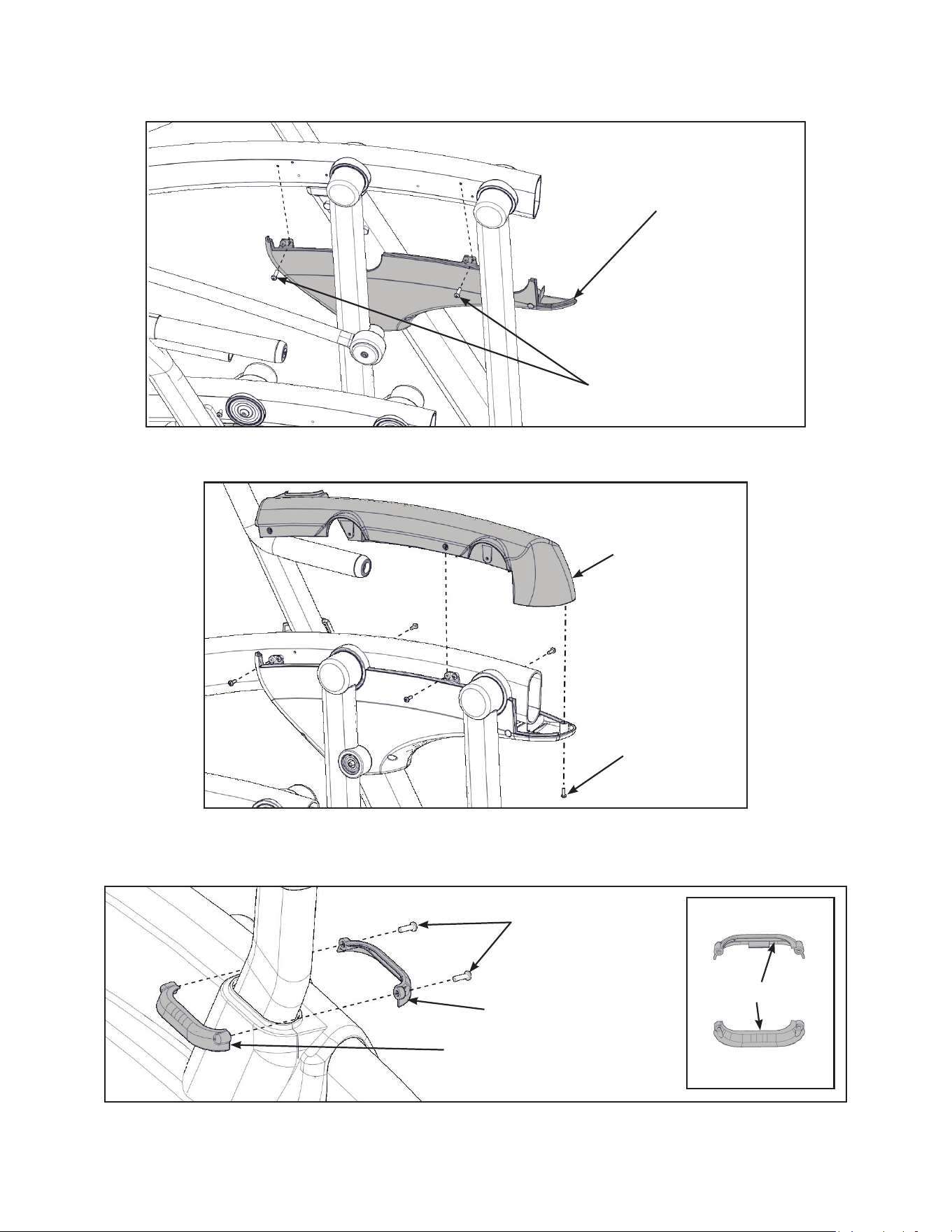
Install handrails
1. Remove three bolts and locknuts from the left support leg using two 9/16” open end wrenches.
Keep the two spacers in place.
Locknuts (3)
Spacers (2)
Bolts (3)
Left Handle
2. Install the left handle, three bolts and three locknuts using two 9/16” open end wrenches.
3. Install the left outer rear cover with two screws using a Phillips screwdriver.
Screws (2)
Left Outer
Rear Cover
Cybex Arc Trainer 625A/625AT Owner’s Manual
23
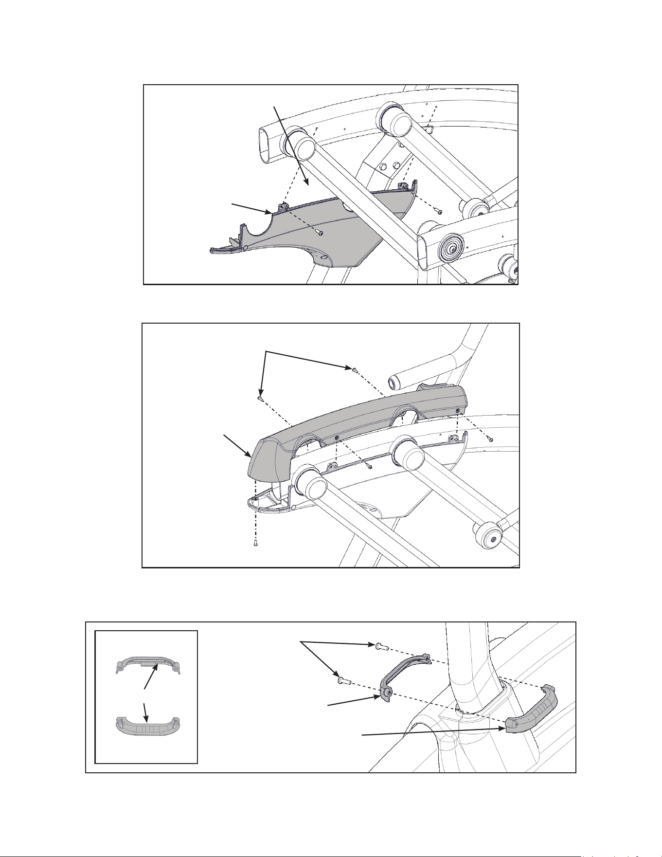
4. Install the left inner rear cover with ve screws using a Phillips screwdriver.
Screws (5)
Left Inner
Rear Cover
5. Install the left top rear cover with ve screws using a Phillips screwdriver.
Screws (5)
Left Top
Rear Cover
6. Install the left inner and outer collars with two screws using a Phillips screwdriver. Collars are
marked with an “L” on the inside and have a left and right side.
Screws (2)
Left Outer Collar
Left Inner Collar
“L”
Cybex Arc Trainer 625A/625AT Owner’s Manual Cybex Arc Trainer 625A/625AT Owner’s Manual
24
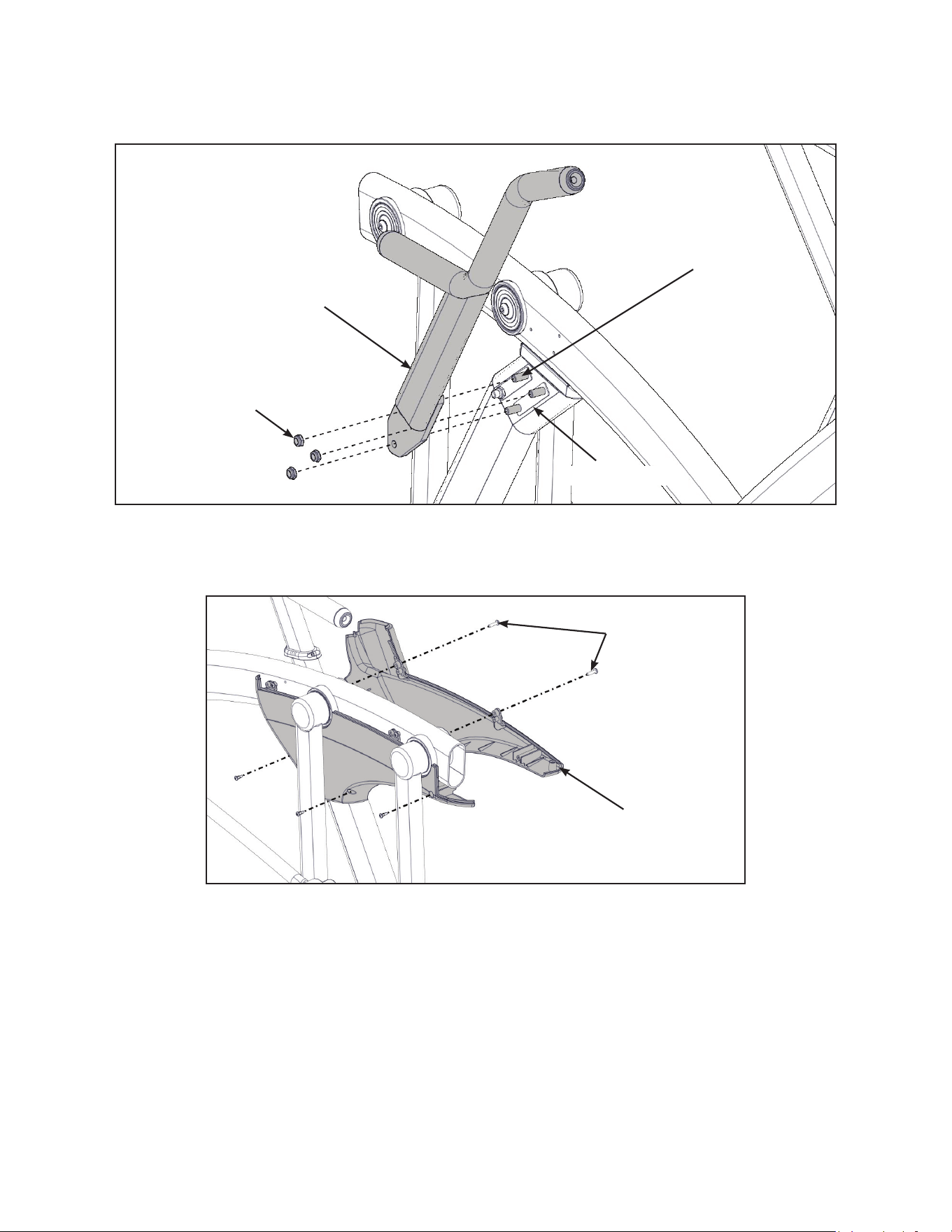
7. Remove three bolts and locknuts from the right support leg using two 9/16” open end
wrenches. Keep the two spacers in place.
Locknuts (3)
Spacers (2)
Bolts (3)
Right Handle
8. Install the right handle, three bolts and three locknuts using two 9/16” open end wrenches.
9. Install the right outer rear cover with two screws using a Phillips screwdriver.
Screws (2)
Right Outer
Rear Cover
Cybex Arc Trainer 625A/625AT Owner’s Manual
25
10.Install the right inner rear cover with ve screws using a Phillips screwdriver.
Screws (2)
Right Inner
Rear Cover
11.Install the right top rear cover with ve screws using a Phillips screwdriver.
Screws (5)
Right Top
Rear Cover
12.Install the right inner and outer collars with two screws using a Phillips screwdriver. Collars are
marked with an “R” on the inside and have a left and right side.
Screws (2)
Right Outer Collar
Right Inner Collar
“R”

Cybex Arc Trainer 625A/625AT Owner’s Manual Cybex Arc Trainer 625A/625AT Owner’s Manual
26
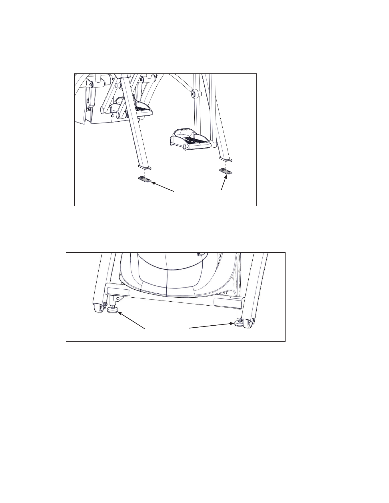
Attach foot pads
Have one person lift the unit while a second person places a foot pad under each of the two back
feet.
Foot Pads (2)
Level unit
Conrm unit is on a level surface. If not, use a 9/16” open-end wrench to adjust the leveling feet up or
down.
Leveling Feet
Visually inspect unit
1. Carefully remove any package material from arms and rest of unit.
2. Carefully examine the unit to ensure assembly is correct and complete.

Cybex Arc Trainer 625A/625AT Owner’s Manual
27
625AT Assembly
The words “left” and “right” denote the user’s orientation.
Read and understand all instructions thoroughly before assembling this unit. Check all items
carefully. If there is damage, see the Customer Service section of this manual for proper procedure to
return, replace, or reorder parts.
Verify correct package
1. Read box label to verify the model number and voltage (optional) match what was ordered.
2. Lift and remove cardboard sleeve surrounding unit.
3. Verify paint color matches what was ordered.
Tools Required
• Phillips screwdriver
• Stubby Phillips screwdriver
• 3/16” Allen wrench (supplied)
• 7/32” Allen wrench (2) (supplied)
• 9/16” Open end wrench (2)
Two people will be required for this procedure. It is the responsibility of the facility owner/owner of the
equipment to ensure that there is appropriate clearance around each machine to allow for safe use
and passage.
Unpack and verify contents of carton
See content listing and diagram below for carton contents. See Customer Service for contact
information if any parts are missing.
Item Quantity Part Number Description
1 1 Varies Base with covers attached
2 1 Varies Console assembly
3 2 12090-322 Foot pad
4 1 770A-316 Base, Accessory tray
5 1 770A-317 Cover, Top, Accessory tray
6 1 770A-318 Cover, Bottom, Accessory tray
7 1 625A-312 Cover, Rear, Top, Right
8 1 625A-313 Cover, Rear, Outer, Right
9 1 770A-324 Cover, Rear, Inner, Right
10 1 625A-310 Cover, Rear, Top, Left
11 1 770A-321 Cover, Rear, Inner, Left
12 1 625A-311 Cover, Rear, Outer, Left
13 1 NA Hardware pack
14 1 5625-4 Owner’s Manual
15 1 625AT-300 Assembly poster
Cybex Arc Trainer 625A/625AT Owner’s Manual Cybex Arc Trainer 625A/625AT Owner’s Manual
28
Item Quantity Part Number Description
16 1 770A-415 Commercial Arc warranty sheet
17 1 770A-416 Consumer Arc warranty sheet
#7
#8
#11
#9
#12
#10#5
#2
#3
#4
#13
#14 #15 #16 #17
#1
#6
Cybex Arc Trainer 625A/625AT Owner’s Manual
29
Verify contents of hardware pack
See hardware pack listings and hardware pack contents. See Customer Service for contact
information if any parts are missing.
Item Quantity Part Number Description
18 2 600A-311 Flange Spacer
19 1 BK030201 3/16” Allen Wrench
20 2 BK030204 7/32” Allen Wrench
21 4 HC700428 BHSCS .375-16 x 2.25”
22 1 HF540200 Grommet, Nylon
23 4 HN704901 Locknut, .375-16 Nylon
24 4 HT592526 Tap Sc 10-12 x 2.00 Pn Hd Phil
25 2 HS307601 Washer, Flat .281 ID x .500 OD x .062”
26 2 HT532512 Screw, Pan Head Phillips, #6 x .50”
27 19 HT552512 Screw, Pan Head Phillips, 8-16 x .50”
28 8 HT572515 Screw, Pan Head Phillips, 10-24 x .75”
29 2 HX622815 SHCS .250-20 UNC-3A SS
30 3 PL-16535 Linkage Rod Cap 2.00 OD (1 extra)
31 1 YA000201 Loctite
625AT Hardware
#18
#24 #25
#19
#26
#20
#27
#21
#28
#22
#30#29
#23
#31
Cybex Arc Trainer 625A/625AT Owner’s Manual Cybex Arc Trainer 625A/625AT Owner’s Manual
30
#7
#8
#11
#29
#25
#30
#18
#9
#12
#26
#24
#21
#28
#27
#28
#27
#27
#27
#28
#27
#23
#22
#27
#10
#5
#2
#3
#4
#1
#6
Cybex Arc Trainer 625A/625AT Owner’s Manual
31
Lift and move unit
1. Remove large bolts and shipping supports. Keep package material on linkage arms at this
time. This will protect the paint from scratching during assembly.
2. Grasp each rear support leg rmly and lift with one person on each side.
3. Lift the lower rear support legs using proper lifting methods so the front transport wheels are
able to roll on floor.
4. Move unit to intended location.
5. Lower rear support legs.
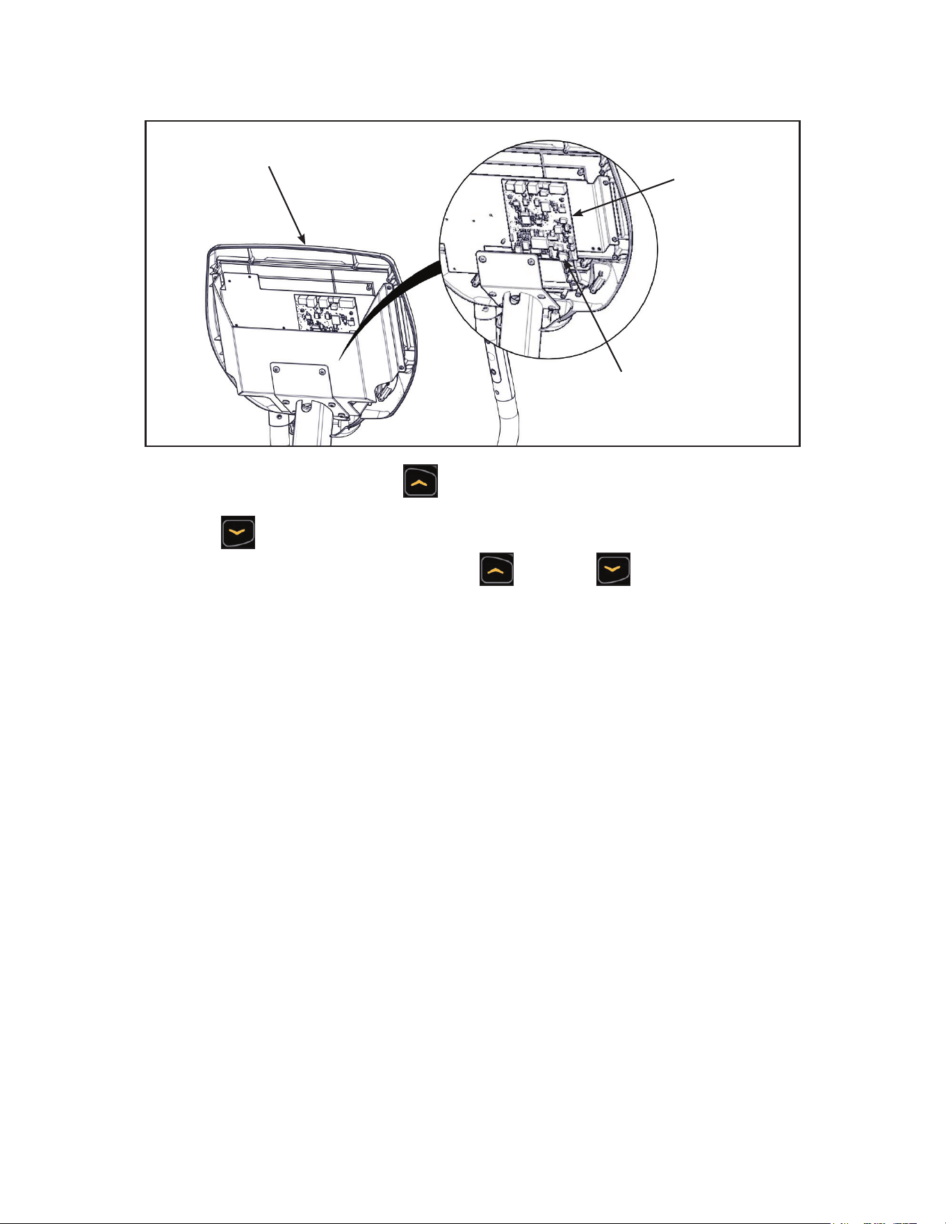
Attach 625AT console assembly
1. Plug the upper heart rate cable into the lower heart rate cable.
Lower Heart
Rate Cable
Upper Heart
Rate Cable
Upper Display
Cable
Console
Locknuts (4)
Bolts (4)
Frame
Lower Display
Cable
2. Place the console into position on the frame. Do not pinch cables while lowering the console.
3. Insert (from underneath) the four bolts into the frame and console.
4. Thread the four locknuts onto the bolts by hand.
5. Tighten the four bolts and locknuts with a 7/32” Allen wrench and a 9/16” open-end wrench.
6. Plug the upper display cable into the lower display cable.
Cybex Arc Trainer 625A/625AT Owner’s Manual Cybex Arc Trainer 625A/625AT Owner’s Manual
32
Install accessory tray base
1. Place the accessory tray base in position on the frame.
Screws (4)
Frame
Accessory
Tray Base
2. Install the four screws using a stubby Phillips screwdriver.
Install accessory tray top
1. Place the accessory tray top in position on the accessory tray base.
Screws (2)
Accessory
Tray Top
Accessory
Tray Base
2. Install the two screws using a stubby Phillips screwdriver.
Cybex Arc Trainer 625A/625AT Owner’s Manual
33
Install accessory tray bottom
1. Install the nylon grommet into the square hole in the frame.
Square
Hole
Frame
Nylon
Grommet
2. Install the accessory tray bottom to the accessory tray base with three screws using a Phillips
screwdriver.
Screws (2)
Screw
Accessory
Tray Base
Accessory
Tray Bottom
Cybex Arc Trainer 625A/625AT Owner’s Manual Cybex Arc Trainer 625A/625AT Owner’s Manual
34
Remove left and right handle assembly
The left and right handle assemblies are shipped in rotated positions. The handle assemblies must be
removed and rotated 180 degrees for proper setup and assembly.
Shipping
Position
1. Remove a screw and washer from the left handle assembly using two 7/32” Allen wrenches.
Left
Handle
Washer
Pivot Pin Assembly
Screw
2. Slide pivot pin assembly out and remove left handle assembly.
3. Rotate left handle assembly 180 degrees.
4. Apply Loctite to threads inside the pivot pin and screw.
5. Place left handle assembly in position and slide pivot pin assembly back in place.
6. Install the screw and washer to the left handle assembly using two 7/32” Allen wrenches.
Cybex Arc Trainer 625A/625AT Owner’s Manual
35
7. Remove a screw and washer from the right handle assembly using two 7/32” Allen wrenches.
Right
Handle
Washer
Screw
Pivot Pin Assembly
8. Slide pivot pin assembly out and remove right handle assembly.
9. Rotate right handle assembly 180 degrees.
10.Apply Loctite to threads inside the pivot pin and screw.
11.Place right handle assembly in position and slide pivot pin assembly back in place.
12.Install the screw and washer to the right handle assembly using two 7/32” Allen wrenches.
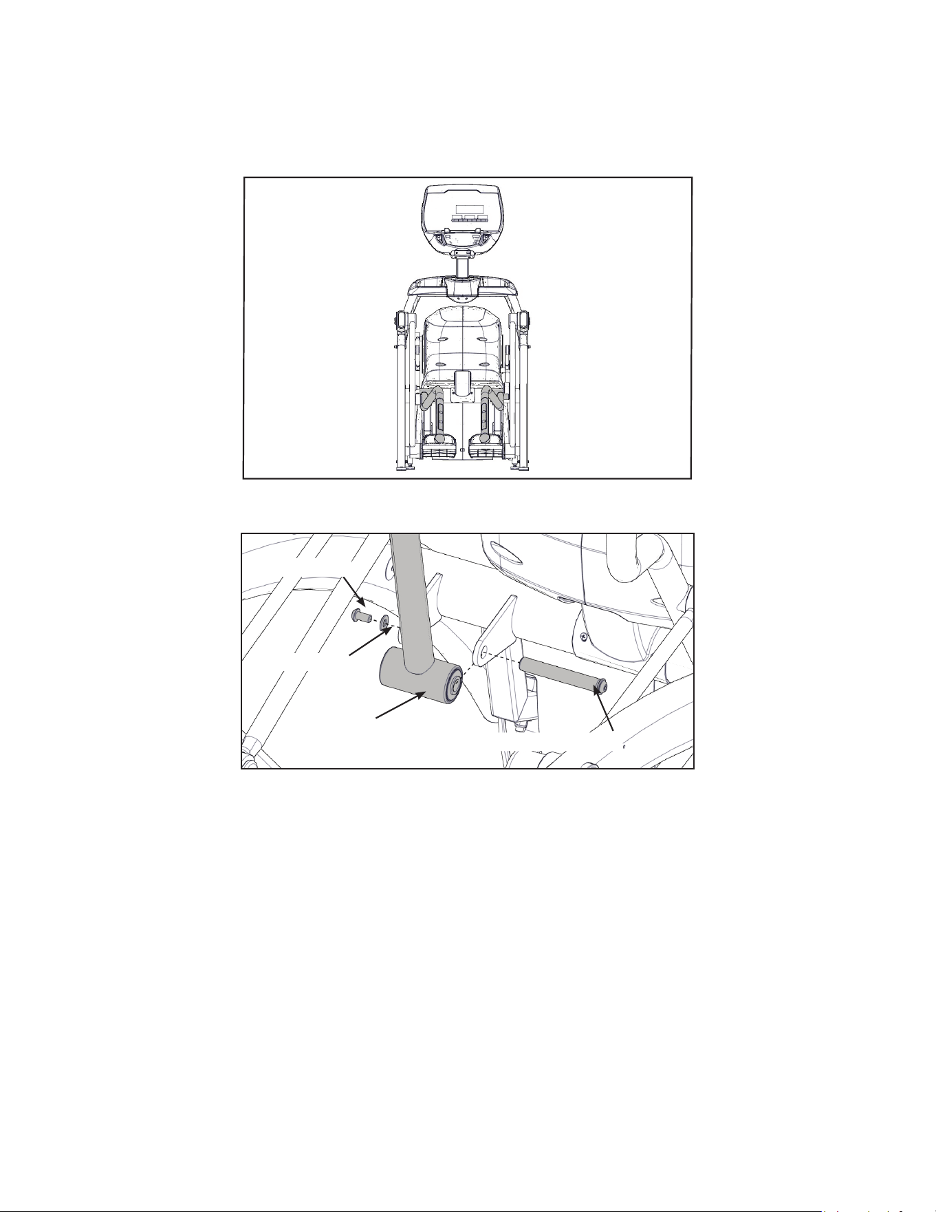
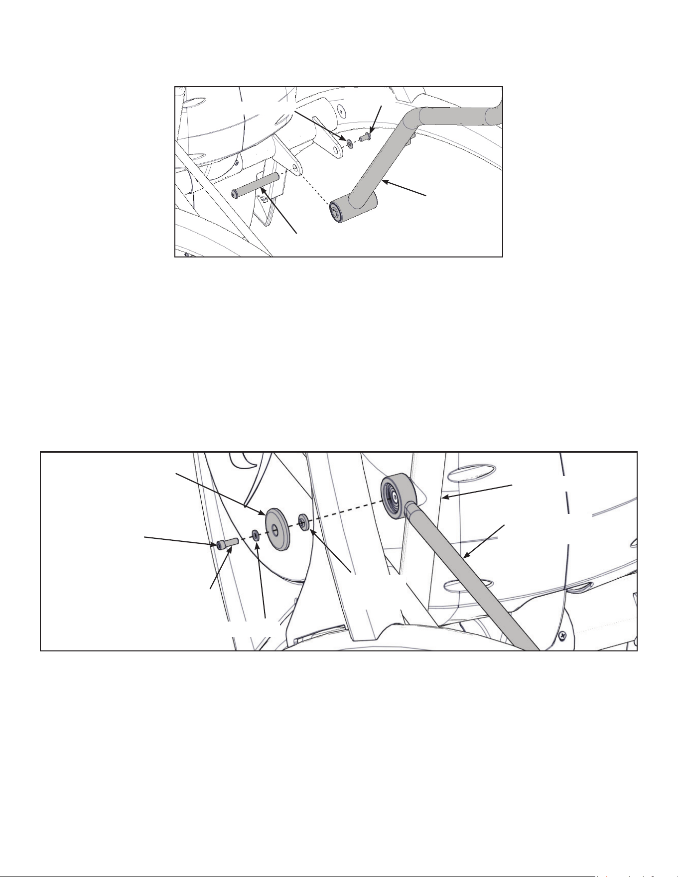
Install the left linkage rod
1. Pivot left handle assembly up and slide left linkage rod onto left arm.
Left Linkage
Rod
Linkage Rod
Cap
Screw
Washer
Left Arm
Flange
Spacer
Loctite
2. Place a drop of Loctite onto the screw.
3. Install the screw, washer, linkage rod cap, and flange spacer using a 3/16” Allen wrench.
4. Tighten screw to a minimum of 90 in/lbs.
Cybex Arc Trainer 625A/625AT Owner’s Manual Cybex Arc Trainer 625A/625AT Owner’s Manual
36
Install right linkage rod
1. Pivot right handle assembly up and slide left linkage rod onto left arm.
Right Linkage
Rod
Linkage Rod
Cap
Screw
Washer
Right Arm
Flange
Spacer
Loctite
2. Place a drop of Loctite onto the screw.
3. Install the screw, washer, linkage rod cap, and flange spacer using a 3/16” Allen wrench.
4. Tighten screw to a minimum of 90 in/lbs.
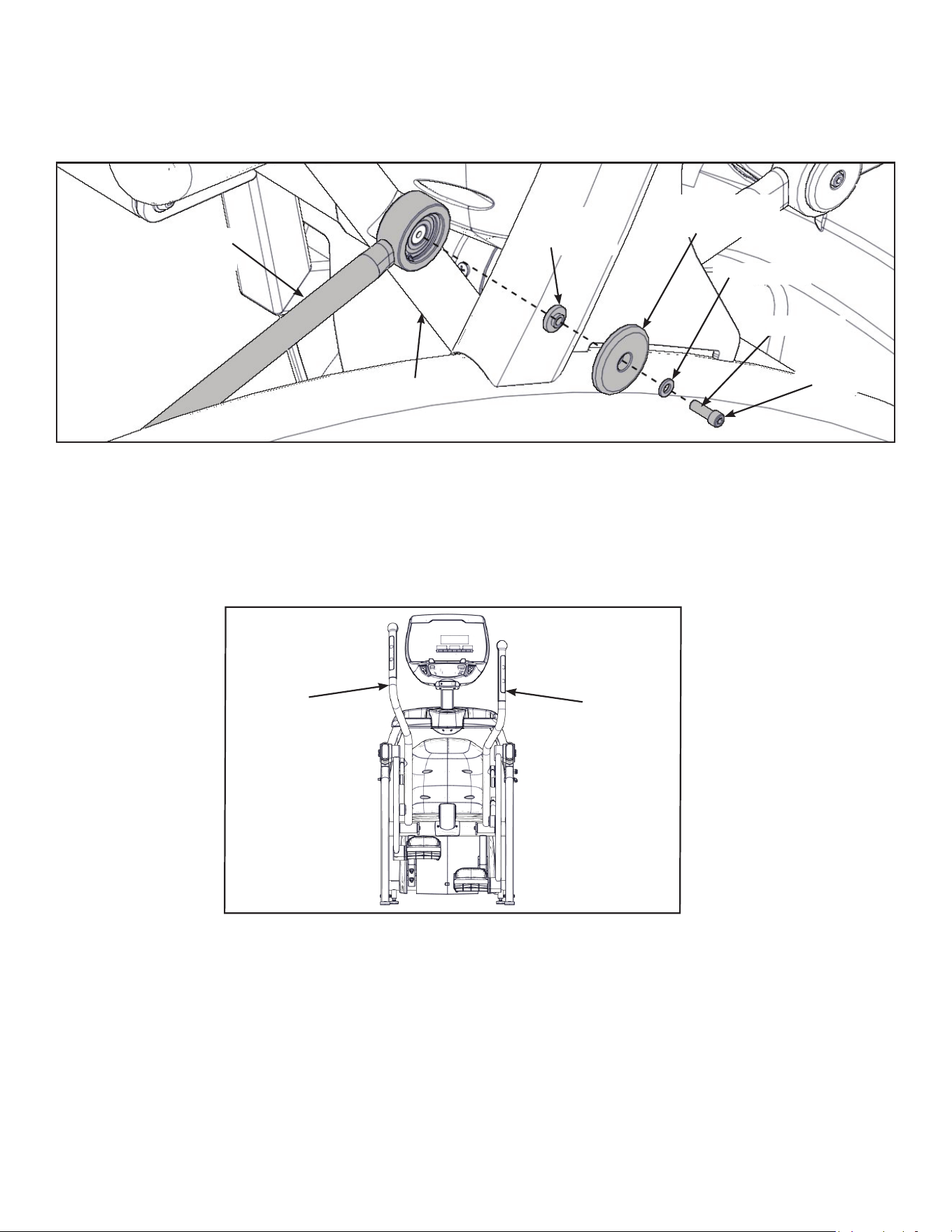
Verify handle assemblies are now installed in the correct position.
Correct
Position
Left
Handle
Assembly
Right
Handle
Assembly
Cybex Arc Trainer 625A/625AT Owner’s Manual
37
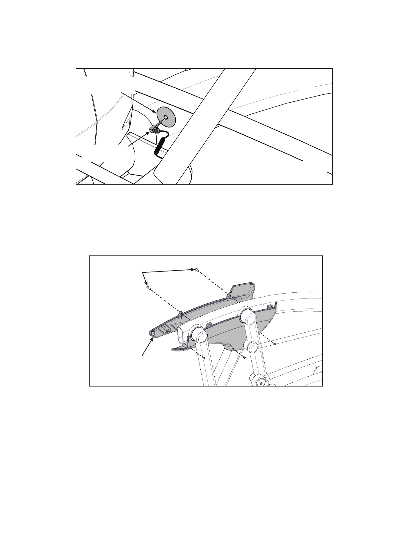
Connect contact heart rate cable
1. Plug right heart rate cable into main frame socket.
Heart Rate
Wire
Main Frame
Socket
Right Side
Shown
Position plug so handle does not
rubcableduringoperation.
2. Plug left heart rate cable into main frame socket.
Verify heart rate cables do not rub on handle during operation.
Installrearcovers.
1. Install the left outer rear cover with two screws using a Phillips screwdriver.
Screws (2)
Left Outer
Rear Cover
Cybex Arc Trainer 625A/625AT Owner’s Manual Cybex Arc Trainer 625A/625AT Owner’s Manual
38
2. Install the left inner rear cover with two screws using a Phillips screwdriver.
Screws (2)
Left Inner
Rear Cover
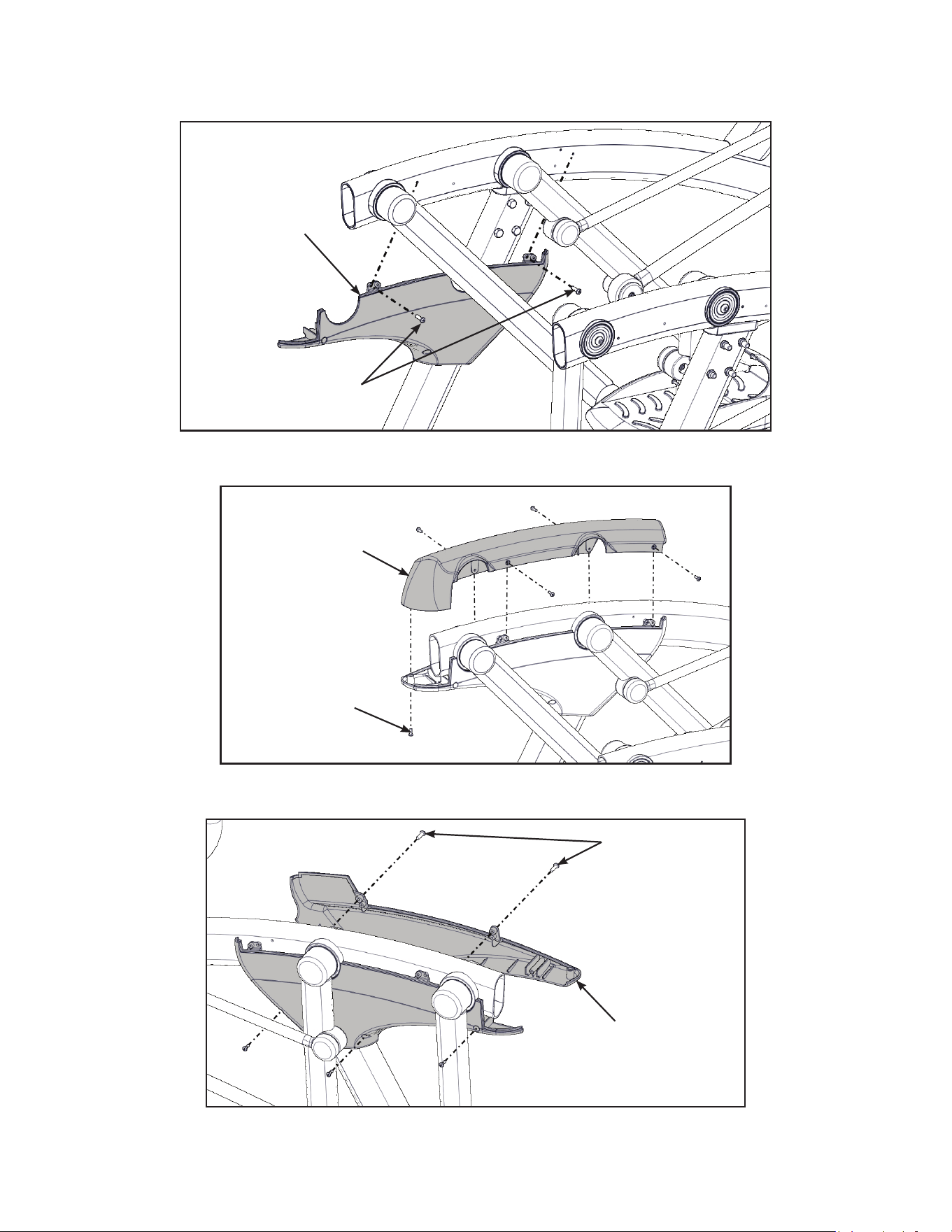
3. Install the left top rear cover with ve screws using a Phillips screwdriver.
Screws (5)
Left Top
Rear Cover
4. Install the right outer rear cover with two screws using a Phillips screwdriver.
Screws (2)
Right Outer
Rear Cover
Cybex Arc Trainer 625A/625AT Owner’s Manual
39
5. Install the right inner rear cover with two screws using a Phillips screwdriver.
Screws (2)
Right Inner
Rear Cover
6. Install the right top rear cover with ve screws using a Phillips screwdriver.
Screws (5)
Right Top
Rear Cover
Cybex Arc Trainer 625A/625AT Owner’s Manual Cybex Arc Trainer 625A/625AT Owner’s Manual
40
Attach foot pads
Have one person lift the unit while a second person places a foot pad under each of the two back
feet.
Foot Pads (2)
Level unit
Conrm unit is on a level surface. If not, use a 9/16” open-end wrench to adjust the leveling feet up or
down.
Leveling Feet
Visually inspect unit
1. Carefully remove any package material from arms and rest of unit.
2. Carefully examine the unit to ensure assembly is correct and complete.
Cybex Arc Trainer 625A/625AT Owner’s Manual
41
Setup
Use the following instructions to setup the units settings.
1. Plug the optional power cord into a power outlet from a grounded circuit, See Electrical
Requirements. Coil up the remainder of the power cord and place it out of the way. The
control panel will light up and be in the Dormant Mode.
2. Hold the handrails to steady self while stepping into the foot plates.
3. Begin striding.
Setup options
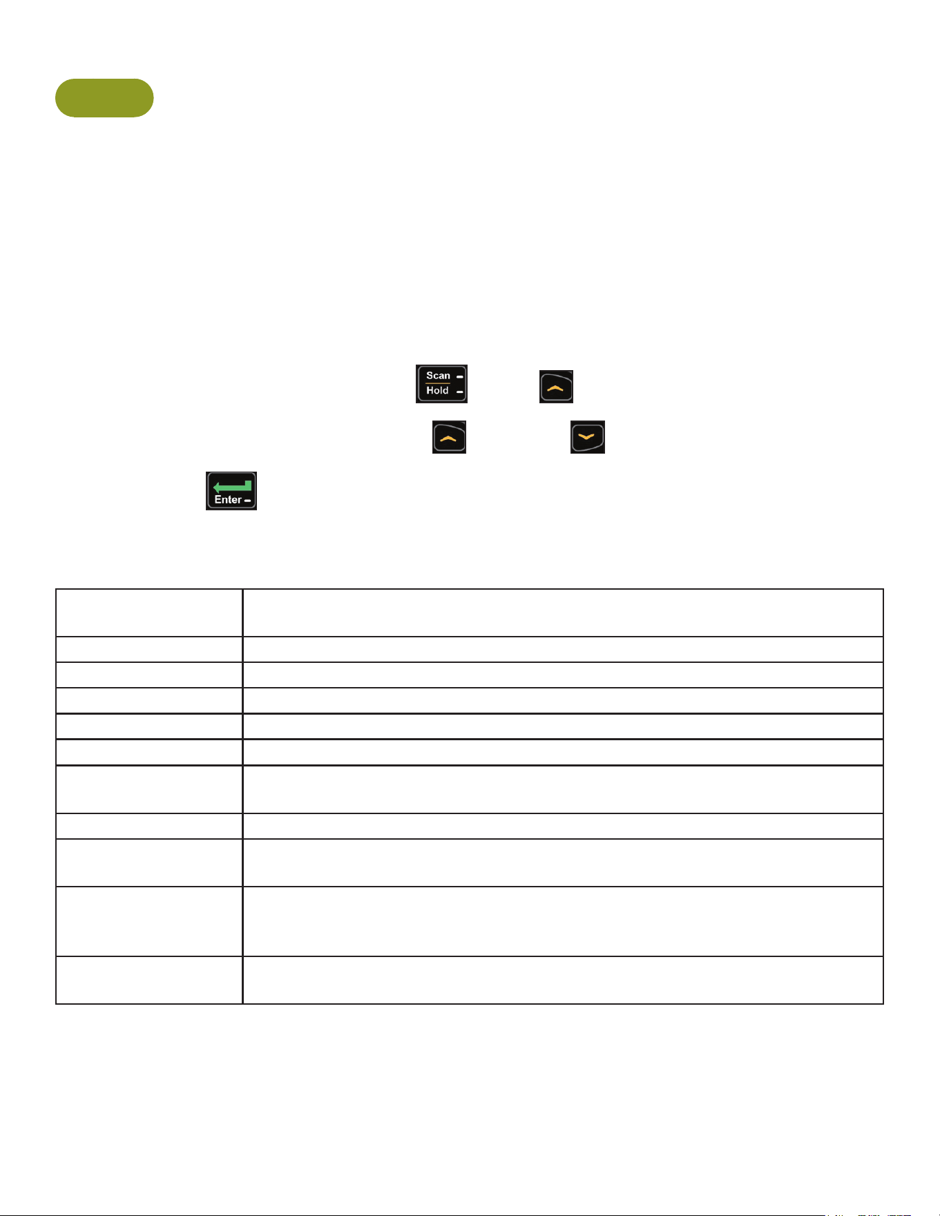
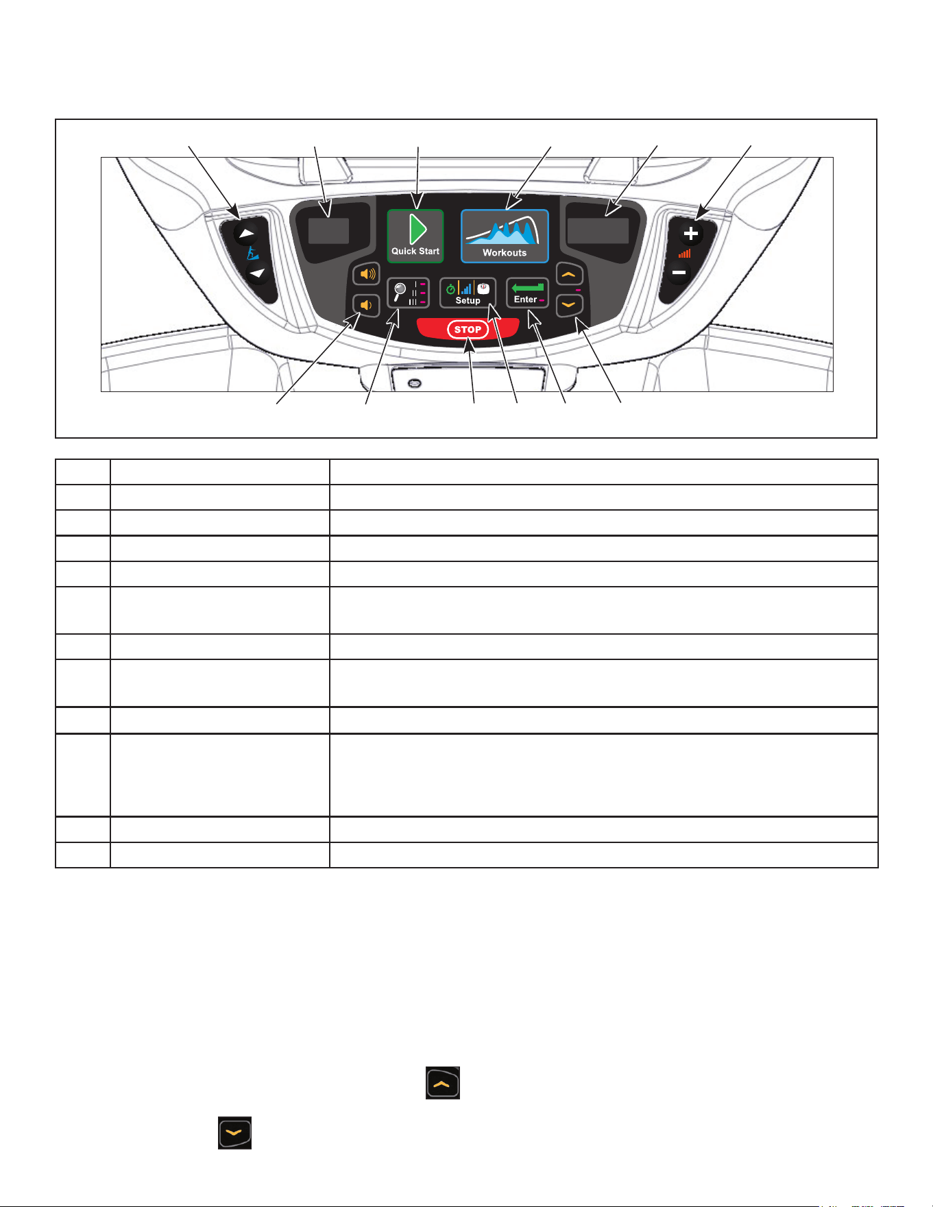
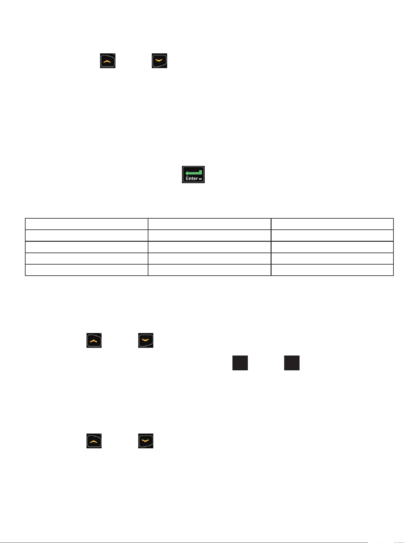
1. Press and the hold the SCAN/HOLD and UP keys for 3 seconds.
Navigate through the setup menu with the UP and DOWN keys.
Press the ENTER key once to enter setup values. Press again to save any changes and
advance forward in the menu.
The Setup options are:
Time Set time display format. 12Hr A, 12Hr P or 24Hr (12 Hour AM, 12 Hour PM or
24 Hour).
Date Date format is [YYYY] [MM] [DD]. Y - Year, M - Month and D - Day.
Distance Units MI - Miles or KM - Kilometers.
Weight Units LBS - Pounds, KG - Kilograms or Stone - Stones.
Pause Set time length for Pause. OFF (Default), 0:30, 1:00 or 2:00 minutes.
Default Time Set default workout time. 10, 20, 30 (Default), 60 or 90 minutes.
Max Time Set maximum workout time. OFF (Unlimited), 20, 30, 40, 50, 60 (Default), 90
or 120 minutes.
Tone Toggle console beeper On (Default) or OFF.
Dormant Style Default, Default with time (Clock shown), Heart only or Energy Saver (All
LED’s off except for center dashes on membrane.
A/V Set A/V option. none (Default), “UHF” or “FM”. See A/V Cong and FM Radio
Presets for full conguration. If unit ships with embedded PEM this setup
option is skipped.
Cloning Transfer setup settings from one unit to others. See Transfer settngs to other
units (optional).
Cybex Arc Trainer 625A/625AT Owner’s Manual Cybex Arc Trainer 625A/625AT Owner’s Manual
42
To reset setup options to default values
1. Press the SCAN/HOLD key at the rst setup option screen (Time). The console will
display “RESET” and “[dEFA] [ULtS] [? ]“.
To exit without resetting, press the UP and DOWN keys or the ENTER key.
2. Press the SCAN/HOLD key to reset the console to the default values. The console will
beep twice and display “RESET” and “[dEFA] [ULtS] [Set]“.
Exit Set Up Mode.
1. Press the Pause key to exit Setup options.
Transfer settings to other units (optional)
After completing setup on one unit the settings can be loaded to other units. Settings can ONLY be
transferred between 625A/625AT Arc Trainers. Do NOT transfer settings between other Arc Trainers,
Bikes or Treadmills.
Tools Required
• Phillips screwdriver
• Cybex USB stick, (Not included). Ensure USB stick is blank.
Save settings to USB stick
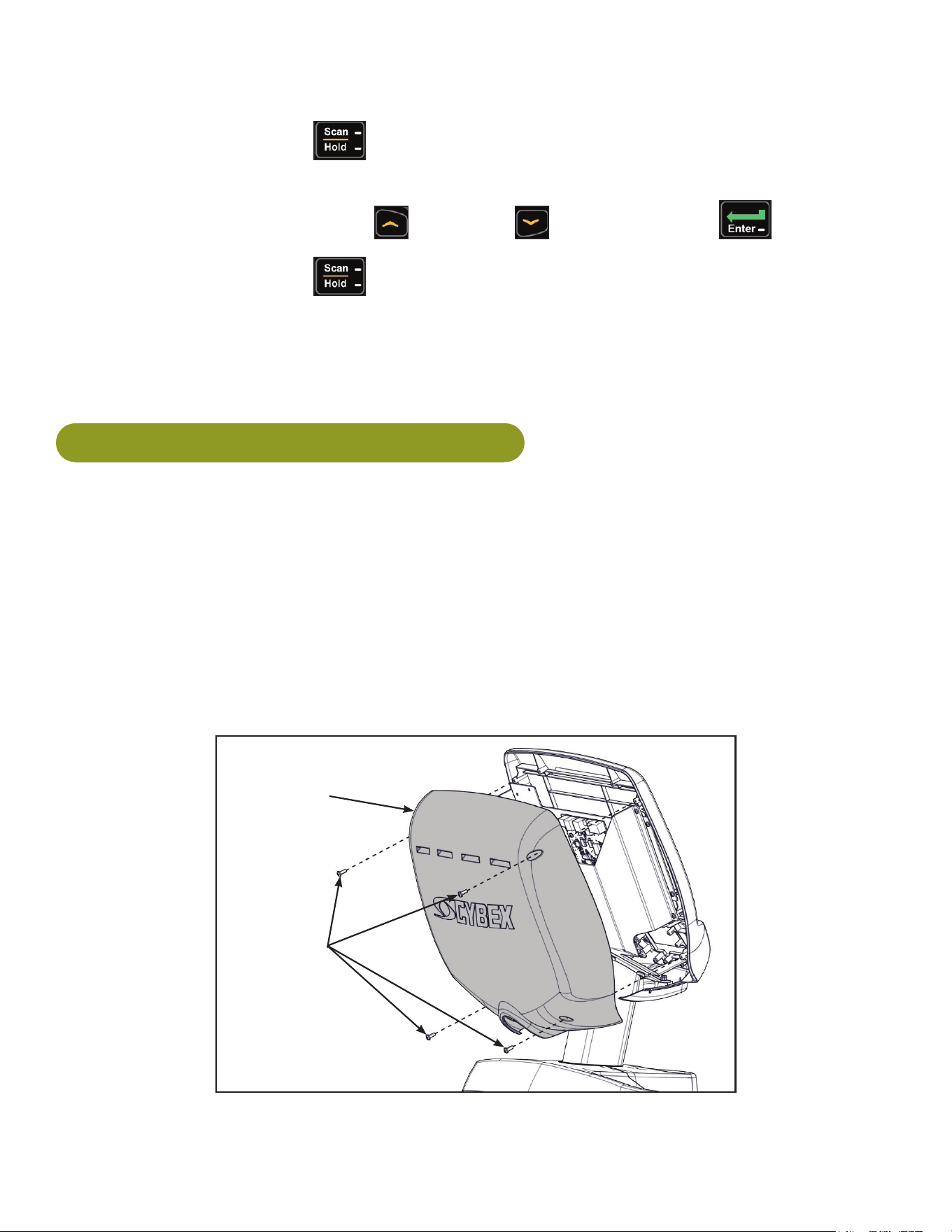
1. Remove the four screws from the back cover using a Phillips screwdriver.
Back
Cover
Screws (4)
2. Remove back cover.
Cybex Arc Trainer 625A/625AT Owner’s Manual
43
3. Plug the USB stick into the USB port of the MCC board.
Console
USB Port
MCC Board
4. Press and hold Scan/Hold and TV Up for 3 seconds.
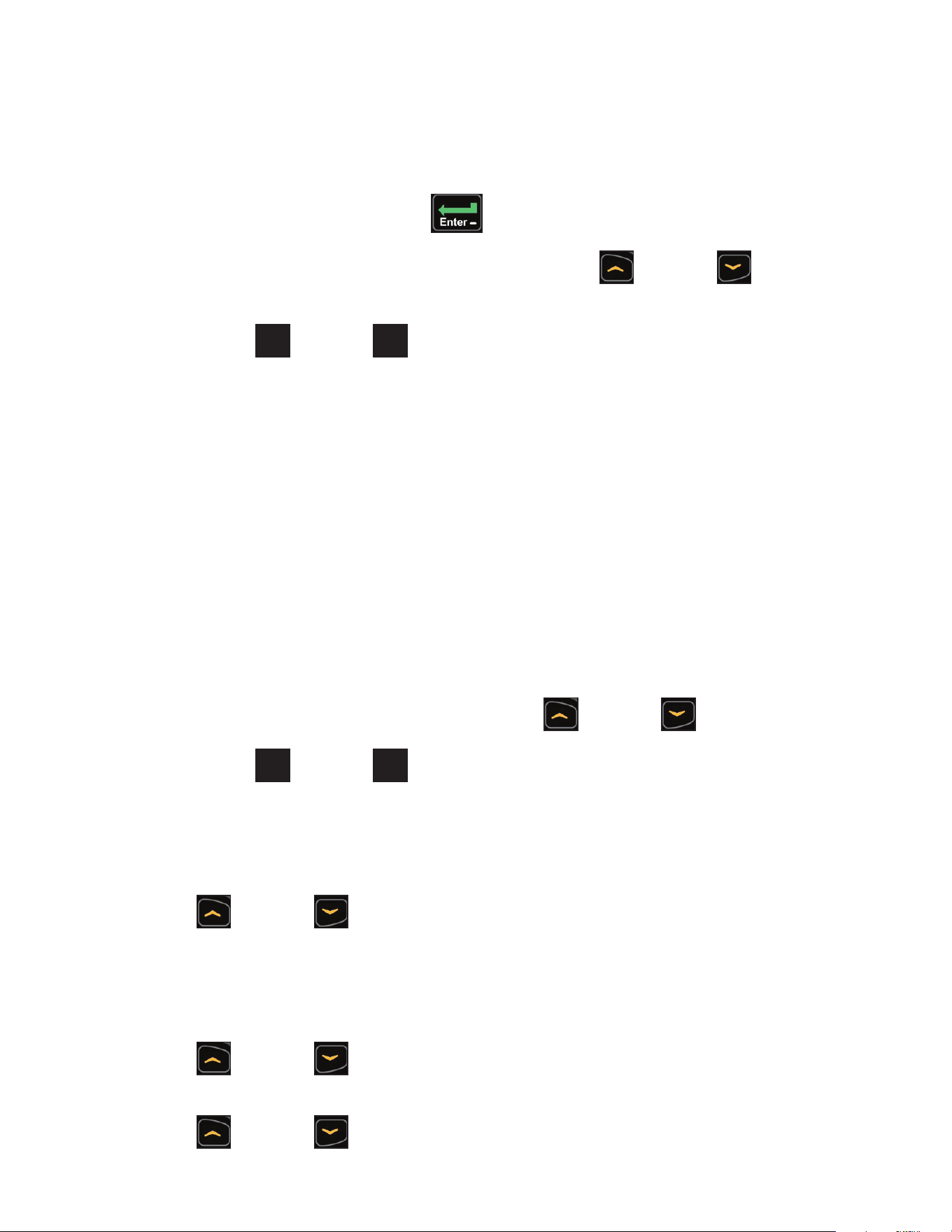
5. Press Down to navigate to “Cloning”. The console will display “SAVE [FILE] [ on ] [USB]”
6. Press Enter to save settings to USB stick. Console will beep four times when complete.
7. Press Pause and remove USB stick.
8. Install the back cover with four screws using a Phillips screwdriver.
Transfer settings to another unit
1. Remove the four screws from the back cover using a Phillips screwdriver.
Back
Cover
Screws (4)
2. Remove back cover.
Cybex Arc Trainer 625A/625AT Owner’s Manual Cybex Arc Trainer 625A/625AT Owner’s Manual
44
3. Plug the USB stick into the USB port of the MCC board.
Console
USB Port
MCC Board
4. Press and hold Scan/Hold and Up for 3 seconds.
5. Press Down to navigate to “Cloning”. The console will display “LOAD [FILE] [ oFF ]
[USB]”. If “LOAD” is not displayed, press Up or Down to toggle setting from “SAVE”
to “LOAD”
6. Press Enter to save settings to USB stick. Console will beep four times when complete.
7. Press Pause and remove USB stick.
8. Install the back cover with four screws using a Phillips screwdriver.
Cybex Arc Trainer 625A/625AT Owner’s Manual
45
A/V Config and FM Radio Presets
Setting up the optional Cybex Wireless Audio Receiver Module for a 625A/625AT requires
three steps:
• Determine the type of transmitter used (MYE 900MHz, Broadcast Vision 863MHz, etc. or TV FM).
• Assign a TV channel number to each transmitter on the 625A/625AT console.
• Add FM radio station presets (optional)
Tools Required:
• Headphones (not included)
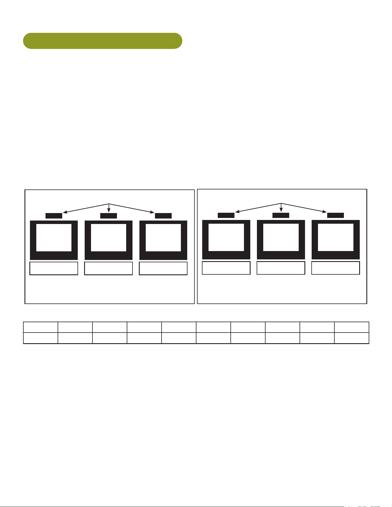
Determine transmitter type
There are two types of transmitters UHF or TV FM. UHF transmitters will have TV’s identied by
number, example TV1. TV FM transmitters will have TV’s identied with FM frequencies,
example 93.1.
UHF Transmitters
Follow procedure:
Setup UHF Transmitters
TV1 TV2 TV3
Follow procedure:
Setup TV FM Transmitters
TV FM Transmitters
93.1 97.5 102.7
For TV FM transmitters, record FM frequencies for all TV’s:
1 2 3 4 5 6 7 8 9 10
Cybex Arc Trainer 625A/625AT Owner’s Manual Cybex Arc Trainer 625A/625AT Owner’s Manual
46
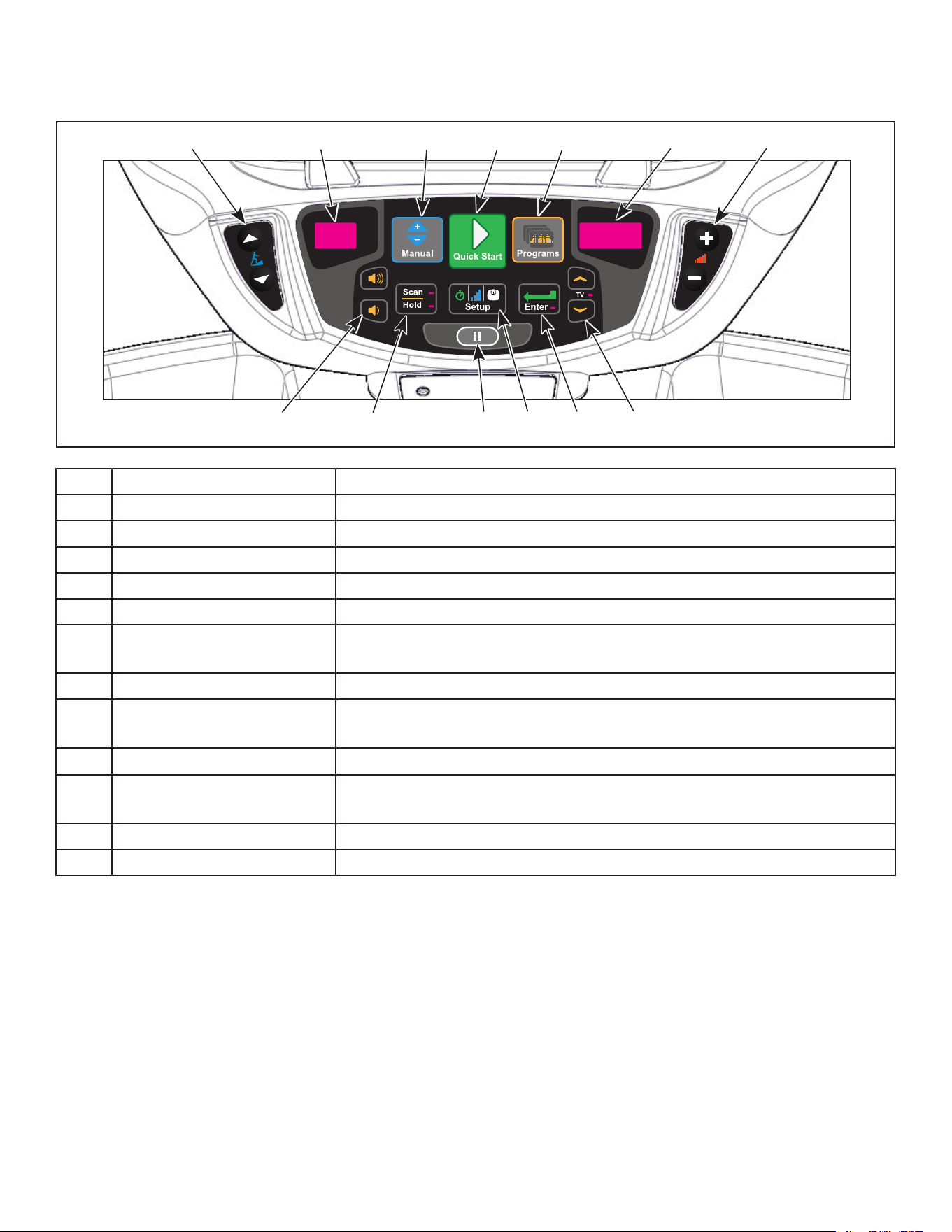
Membrane with Progams key
1 2 3 54 6 7
9 1110 12 138
1 Incline keys Navigates through all stored channels as in User Mode
2 Incline display Shows setting of receiver sensitivity as (n)ear or (F)ar
3 Manual key Toggles near/far for receiver sensitivity
4 Quick Start key Selects transmitter type Resets all stored TV channels when used
5 Programs key Toggles setup for FM presets and back to TV channel setup
6 Resistance display Shows ‘FM’ when storing FM radio station presets
7 Resistance keys Toggles the display for Adding new channels or Deleting stored
channels
8 Volume keys Increase or decrease volume
9 Scan/Hold key Scans for available TV transmitters, or will seek the next strongest
FM station or FM transmitter frequency
10 Pause key Stores and exits setup
11 Setup key When storing FM presets, this button will clear all stored FM radio
presets
12 Enter key Enters menu, accepts value shown, moves forward in menu
13 Up/Down keys Navigates TV channels or manually tunes FM frequencies
Cybex Arc Trainer 625A/625AT Owner’s Manual
47
Membrane with Workouts key
1 2 3 4 5 6
8 109 11 127
1 Incline keys Navigates through all stored channels as in User Mode
2 Incline display Shows setting of receiver sensitivity as (n)ear or (F)ar
3 Quick Start key Selects transmitter type Resets all stored TV channels when used
4 Workouts key Toggles setup for FM presets and back to TV channel setup
5 Resistance display Shows ‘FM’ when storing FM radio station presets
6 Resistance keys Toggles the display for Adding new channels or Deleting stored
channels
7 Volume keys Increase or decrease volume
8 Display option key Scans for available TV transmitters, or will seek the next strongest
FM station or FM transmitter frequency
9 STOP key Stores and exits setup
10 Setup key When storing FM presets, this button will clear all stored FM radio
presets
Toggles near/far for receiver sensitivity
11 Enter key Enters menu, accepts value shown, moves forward in menu
12 Up/Down keys Navigates TV channels or manually tunes FM frequencies
A/V setup mode
1. Plug the optional power cord into a power outlet from a grounded circuit, See Electrical
Requirements. Coil up the remainder of the power cord and place it out of the way. The
control panel will light up and be in the Dormant Mode.
2. Hold the handrails to steady self while stepping into the foot plates.
3. Begin striding.
4. Press and hold Scan/Hold and TV Up
for 3 seconds. Display will show clock icon.
5. Press Down to navigate to the “A/V” screen.
Cybex Arc Trainer 625A/625AT Owner’s Manual Cybex Arc Trainer 625A/625AT Owner’s Manual
48
6. Press Enter to enter setup mode.
7. Press the Up
or Down keys to change A/V type from “none” to “UHF or FM”.
8. Plug in headphones to listen for channels during setup.
Setup UHF Transmitters
For transmitter types 900 MHz, 863 MHz or 806 MHz. Use this procedure to associate channel
numbers to your TV transmitters.
Pick transmitter type:
1. Enter A/V setup mode.
2. Select “UHF” and press the ENTER key.
3. Press Quick Start to select your transmitter type from the available choices. The display will
only show choices available under your transmitter type (900 MHz, 863 MHz or 806 MHz).
900 MHz System 863 MHz System 806 MHz System
“M 900” MYE “M 863” MYE “J1 806” Japan 14 channels
“C 900” Cardio Theater “E 863” Enercise “J2 806” Japan 30 channels
“E 900” Enercise “A 863” Audeon
“B 900” Broadcast Vision
4. Press Scan/Hold to scan for available channels. The scan can take up to 10 seconds and
then display “CH 1 of #”. The “#” symbol is total number of strong UHF channels found. Some
of these channels may not be signals from the TV transmitters and need to be deleted.
Review channels:
1. Press Up
or Down to listen to available channels with the headphones.
2. Delete unwanted channels by pressing Speed Up
SWITCH, THUMB CONTROL,
LEFT, INCLINE
B C
2 OF 2
REVISIONS
DESCRIPTION
See sheet 1
ECO
REV
DATE APPROVAL
BY
10 TROTTER DRIVE
MEDWAY, MA
REV.
SHEET
SIZE
APPROVALS
DRAWN BY
MATERIAL
FINISH
ADOBE GENERATED DRAWING
DO NOT MANUALLY UPDATE
CHECKED
RESP ENG
MFG ENG
QUAL ENG
DATE
DWG. NO.
UNLESS OTHERWISE SPECIFIED
DIMENSIONS ARE IN INCHES
TOLERANCES ARE:
.XX ± .02
.XXX ± .010
ANGULAR = ± 1°
FINISH = 125 RMS
FRACTIONS = ± 1/64”
SCALE: 1=1 THIS FILE IS IN ADOBE ILLUSTRATOR
DO NOT SCALE DRAWING
THE INFORMATION CONTAINED IN THIS DRAWING IS THE SOLE PROPERTY OF CYBEX.
ANY REPRODUCTION IN PART OR WHOLE WITHOUT
THE WRITTEN PERMISSION OF CYBEX IS PROHIBITED.
SEE NOTES, Page 1
SEE NOTES, Page 1
.
.
.
6/28/11
SW-23346
BLACK
PANTONE PRO CYAN C
WHITE
or Down
SWITCH, THUMB CONTROL,
LEFT, INCLINE
B C
2 OF 2
REVISIONS
DESCRIPTION
See sheet 1
ECO
REV
DATE APPROVAL
BY
10 TROTTER DRIVE
MEDWAY, MA
REV.
SHEET
SIZE
APPROVALS
DRAWN BY
MATERIAL
FINISH
ADOBE GENERATED DRAWING
DO NOT MANUALLY UPDATE
CHECKED
RESP ENG
MFG ENG
QUAL ENG
DATE
DWG. NO.
UNLESS OTHERWISE SPECIFIED
DIMENSIONS ARE IN INCHES
TOLERANCES ARE:
.XX ± .02
.XXX ± .010
ANGULAR = ± 1°
FINISH = 125 RMS
FRACTIONS = ± 1/64”
SCALE: 1=1 THIS FILE IS IN ADOBE ILLUSTRATOR
DO NOT SCALE DRAWING
THE INFORMATION CONTAINED IN THIS DRAWING IS THE SOLE PROPERTY OF CYBEX.
ANY REPRODUCTION IN PART OR WHOLE WITHOUT
THE WRITTEN PERMISSION OF CYBEX IS PROHIBITED.
SEE NOTES, Page 1
SEE NOTES, Page 1
.
.
.
6/28/11
SW-23346
BLACK
PANTONE PRO CYAN C
WHITE
to change the right LED
window to [dEL]. Press Enter to delete channel. Repeat process for additional unwanted
channels.
3. Adjust the Near/Far setting for channels that are available but not showing. Press Manual
to change the setting from “F” (Far) to “n” (Near). Press Scan/Hold to re-scan for available
channels.
4. Press Up
or Down to scroll through and verify all TV channels. If all TV transmitters
are stored, and they all correlate the TV number to the correct TV heard, setup is complete.
If not you may need to re-scan or adjust the transmitter codes (see documentation for your
transmitters to perform a code change).
5. Press Pause to exit setup.Transmitter setup complete.
6. Proceed to Add FM Radio Stations (optional).
Cybex Arc Trainer 625A/625AT Owner’s Manual
49
Setup TV FM Transmitters
If your TV’s use FM transmitters, follow these instructions to assign a TV channel to each frequency.
1. Enter A/V setup mode.
2. Select “TV FM” and press the ENTER
key.
3. Press Scan/Hold to seek the next TV FM frequency or Up
or Down to tune
manually.
4. Press Speed Up
SWITCH, THUMB CONTROL,
LEFT, INCLINE
B C
2 OF 2
REVISIONS
DESCRIPTION
See sheet 1
ECO
REV
DATE APPROVAL
BY
10 TROTTER DRIVE
MEDWAY, MA
REV.
SHEET
SIZE
APPROVALS
DRAWN BY
MATERIAL
FINISH
ADOBE GENERATED DRAWING
DO NOT MANUALLY UPDATE
CHECKED
RESP ENG
MFG ENG
QUAL ENG
DATE
DWG. NO.
UNLESS OTHERWISE SPECIFIED
DIMENSIONS ARE IN INCHES
TOLERANCES ARE:
.XX ± .02
.XXX ± .010
ANGULAR = ± 1°
FINISH = 125 RMS
FRACTIONS = ± 1/64”
SCALE: 1=1 THIS FILE IS IN ADOBE ILLUSTRATOR
DO NOT SCALE DRAWING
THE INFORMATION CONTAINED IN THIS DRAWING IS THE SOLE PROPERTY OF CYBEX.
ANY REPRODUCTION IN PART OR WHOLE WITHOUT
THE WRITTEN PERMISSION OF CYBEX IS PROHIBITED.
SEE NOTES, Page 1
SEE NOTES, Page 1
.
.
.
6/28/11
SW-23346
BLACK
PANTONE PRO CYAN C
WHITE
or Down
SWITCH, THUMB CONTROL,
LEFT, INCLINE
B C
2 OF 2
REVISIONS
DESCRIPTION
See sheet 1
ECO
REV
DATE APPROVAL
BY
10 TROTTER DRIVE
MEDWAY, MA
REV.
SHEET
SIZE
APPROVALS
DRAWN BY
MATERIAL
FINISH
ADOBE GENERATED DRAWING
DO NOT MANUALLY UPDATE
CHECKED
RESP ENG
MFG ENG
QUAL ENG
DATE
DWG. NO.
UNLESS OTHERWISE SPECIFIED
DIMENSIONS ARE IN INCHES
TOLERANCES ARE:
.XX ± .02
.XXX ± .010
ANGULAR = ± 1°
FINISH = 125 RMS
FRACTIONS = ± 1/64”
SCALE: 1=1 THIS FILE IS IN ADOBE ILLUSTRATOR
DO NOT SCALE DRAWING
THE INFORMATION CONTAINED IN THIS DRAWING IS THE SOLE PROPERTY OF CYBEX.
ANY REPRODUCTION IN PART OR WHOLE WITHOUT
THE WRITTEN PERMISSION OF CYBEX IS PROHIBITED.
SEE NOTES, Page 1
SEE NOTES, Page 1
.
.
.
6/28/11
SW-23346
BLACK
PANTONE PRO CYAN C
WHITE
keys to add “[Add]” a channel. Press Enter to save
channel, “std” (stored) will be displayed.
5. Repeat steps 3 and 4 to add all TV FM channels.
6. Press Pause to exit setup when all the TV’s FM transmitter frequencies have a TV number.
Transmitter setup complete.
7. Proceed to Add FM Radio Stations (optional).
Add FM Radio Stations (optional)
If strong local FM Radio Stations are available in the area, you can set those as presets.
1. Enter A/V setup mode.
2. Press Programs to display “FM” on the console. The left numeric will display the next
available channel and FM frequency.
3. Press Scan/Hold to seek the next FM station or Up or Down to tune manually.
4. Press Speed Up
SWITCH, THUMB CONTROL,
LEFT, INCLINE
B C
2 OF 2
REVISIONS
DESCRIPTION
See sheet 1
ECO
REV
DATE APPROVAL
BY
10 TROTTER DRIVE
MEDWAY, MA
REV.
SHEET
SIZE
APPROVALS
DRAWN BY
MATERIAL
FINISH
ADOBE GENERATED DRAWING
DO NOT MANUALLY UPDATE
CHECKED
RESP ENG
MFG ENG
QUAL ENG
DATE
DWG. NO.
UNLESS OTHERWISE SPECIFIED
DIMENSIONS ARE IN INCHES
TOLERANCES ARE:
.XX ± .02
.XXX ± .010
ANGULAR = ± 1°
FINISH = 125 RMS
FRACTIONS = ± 1/64”
SCALE: 1=1 THIS FILE IS IN ADOBE ILLUSTRATOR
DO NOT SCALE DRAWING
THE INFORMATION CONTAINED IN THIS DRAWING IS THE SOLE PROPERTY OF CYBEX.
ANY REPRODUCTION IN PART OR WHOLE WITHOUT
THE WRITTEN PERMISSION OF CYBEX IS PROHIBITED.
SEE NOTES, Page 1
SEE NOTES, Page 1
.
.
.
6/28/11
SW-23346
BLACK
PANTONE PRO CYAN C
WHITE
or Down
SWITCH, THUMB CONTROL,
LEFT, INCLINE
B C
2 OF 2
REVISIONS
DESCRIPTION
See sheet 1
ECO
REV
DATE APPROVAL
BY
10 TROTTER DRIVE
MEDWAY, MA
REV.
SHEET
SIZE
APPROVALS
DRAWN BY
MATERIAL
FINISH
ADOBE GENERATED DRAWING
DO NOT MANUALLY UPDATE
CHECKED
RESP ENG
MFG ENG
QUAL ENG
DATE
DWG. NO.
UNLESS OTHERWISE SPECIFIED
DIMENSIONS ARE IN INCHES
TOLERANCES ARE:
.XX ± .02
.XXX ± .010
ANGULAR = ± 1°
FINISH = 125 RMS
FRACTIONS = ± 1/64”
SCALE: 1=1 THIS FILE IS IN ADOBE ILLUSTRATOR
DO NOT SCALE DRAWING
THE INFORMATION CONTAINED IN THIS DRAWING IS THE SOLE PROPERTY OF CYBEX.
ANY REPRODUCTION IN PART OR WHOLE WITHOUT
THE WRITTEN PERMISSION OF CYBEX IS PROHIBITED.
SEE NOTES, Page 1
SEE NOTES, Page 1
.
.
.
6/28/11
SW-23346
BLACK
PANTONE PRO CYAN C
WHITE
keys to add “[Add]” a channel. Press Enter to save
channel, “std” (stored) will be displayed.
5. Repeat steps 3 and 4 to save up to 32 FM radio stations.
6. Press Pause to exit setup when all FM radio stations are stored.
7. Press Up or Down to scroll through and verify all FM radio stations.
Adjust sound volumes
After completing setup, the sound volume should be adjusted between the TV transmitters and the
FM radio stations. If FM radio stations are not set, adjust volume between all TV’s.
1. Press Up or Down to select an FM radio station. This volume is not adjustable and is
the base volume.
2. Press Up
or Down to select a TV station.
Cybex Arc Trainer 625A/625AT Owner’s Manual Cybex Arc Trainer 625A/625AT Owner’s Manual
50
3. Adjust the volume of each TV to match an FM Radio Station or each other using the TV’s
remote control. The goal is for a volume setting of 10 on the treadmill to be the same for all TV
and FM channels.
4. Repeat procedure for all TV’s.
Using the Cybex Wireless Audio Receiver
1. Plug headphones into headphone jack.
2. Press Up or Down to select TV or FM channels.
3. Press volume Up
or Down to adjust volume.
Setup Complete
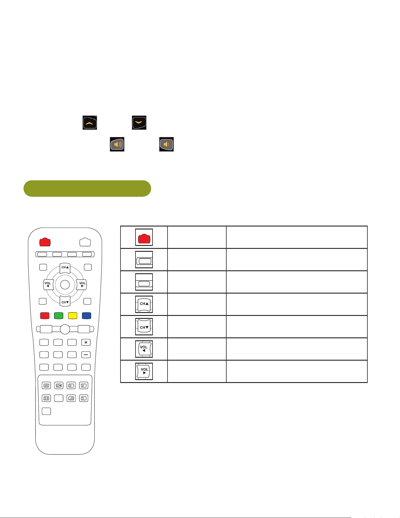
E3 View Monitor Controls
The remote control is used to perform all setup operations for the E3 View Monitor.
POWER MUTE
SETUP TV/AV TV/FM CH LIST
SUBPAGE
HOLD MODE MIX UPDATE
TEXT SIZE INDEX REVEAL
i ?
X
PSM SSM SAP
1 2 3
4 5 6
7 8 9 0
OK
ARC CC
SLEEP LAST
POWER
MUTE
SETUP TV/AV TV/FM CH LIST
SUBPAGE
HOLD MODE MIX UPDATE
TEXT SIZE INDEX REVEAL
i ?
X
PSM SSM SAP
1 2 3
4 5 6
7 8 9 0
OK
ARC CC
SLEEP LAST
POWER Turn the E3 View monitor on or off
POWER MUTE
SETUP
TV/AV TV/FM CH LIST
SUBPAGE
HOLD MODE MIX UPDATE
TEXT SIZE INDEX REVEAL
i ?
X
PSM SSM SAP
1 2 3
4 5 6
7 8 9 0
OK
ARC CC
SLEEP LAST
SETUP Enter or exit the Setup home screen
POWER MUTE
SETUP TV/AV TV/FM
CH LIST
SUBPAGE
HOLD MODE MIX UPDATE
TEXT SIZE INDEX REVEAL
i ?
X
PSM SSM SAP
1 2 3
4 5 6
7 8 9 0
OK
ARC CC
SLEEP LAST
CH LIST Channel list - List all available
channels
POWER MUTE
SETUP TV/AV TV/FM CH LIST
SUBPAGE
HOLD MODE MIX UPDATE
TEXT SIZE INDEX REVEAL
i ?
X
PSM SSM SAP
1 2 3
4 5 6
7 8 9 0
OK
ARC CC
SLEEP LAST
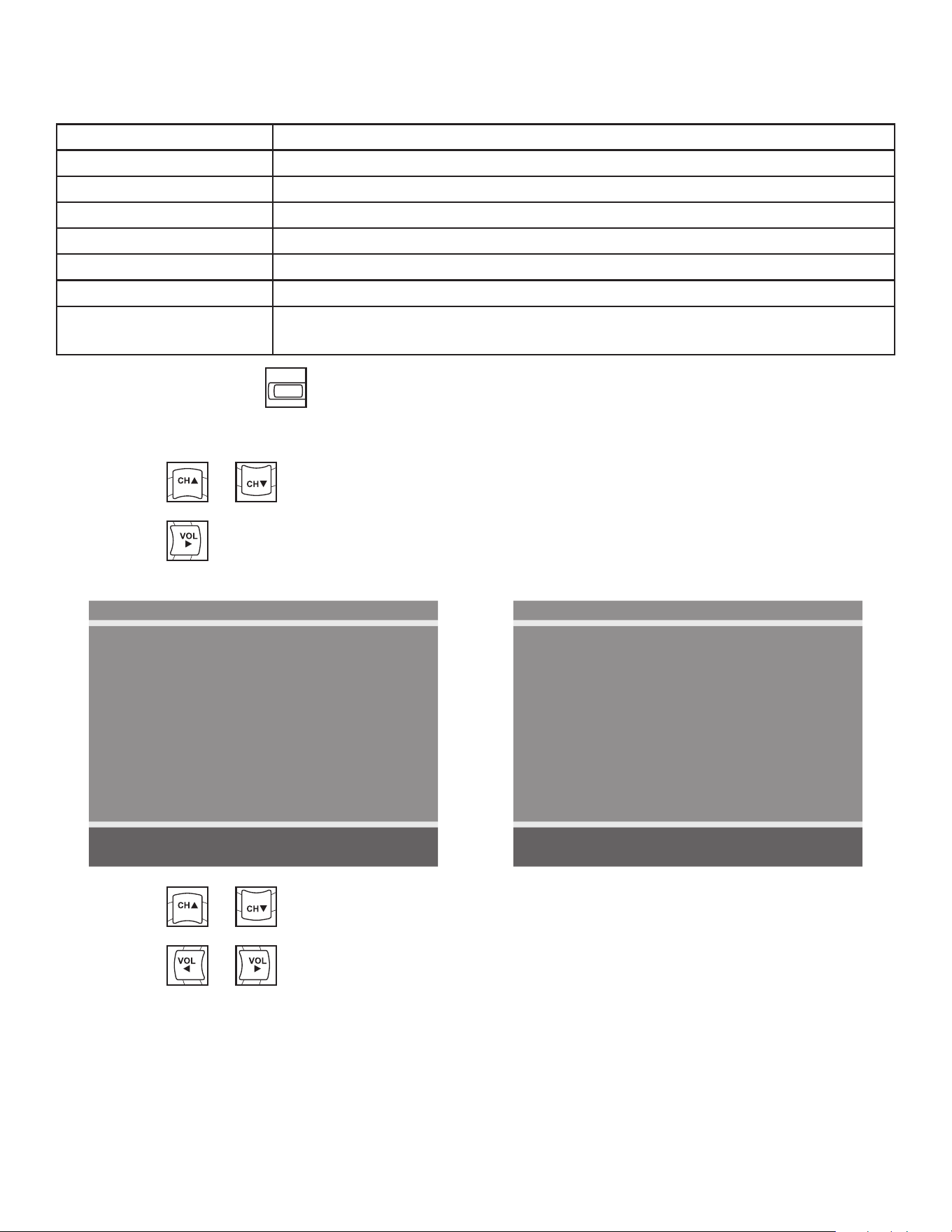
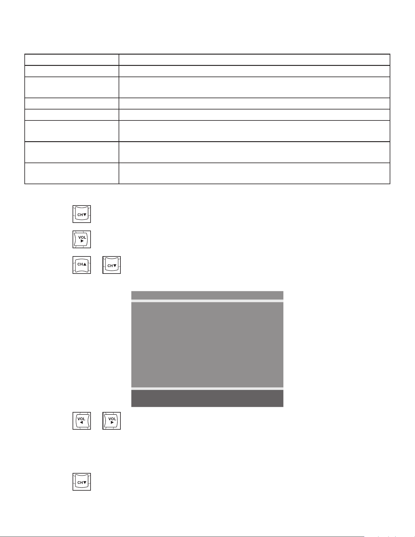
CH▲ Channel up - Navigate up through the
on-screen menu
POWER MUTE
SETUP TV/AV TV/FM CH LIST
SUBPAGE
HOLD MODE MIX UPDATE
TEXT SIZE INDEX REVEAL
i ?
X
PSM SSM SAP
1 2 3
4 5 6
7 8 9 0
OK
ARC CC
SLEEP LAST
CH▼ Channel up - Navigate down through
the on-screen menu
POWER MUTE
SETUP TV/AV TV/FM CH LIST
SUBPAGE
HOLD MODE MIX UPDATE
TEXT SIZE INDEX REVEAL
i ?
X
PSM SSM SAP
1 2 3
4 5 6
7 8 9 0
OK
ARC CC
SLEEP LAST
VOL◄ Volume left - Navigate left through the
on-screen menu
POWER MUTE
SETUP TV/AV TV/FM CH LIST
SUBPAGE
HOLD MODE MIX UPDATE
TEXT SIZE INDEX REVEAL
i ?
X
PSM SSM SAP
1 2 3
4 5 6
7 8 9 0
OK
ARC CC
SLEEP LAST
VOL► Volume right - Navigate right through
the on-screen menu

Cybex Arc Trainer 625A/625AT Owner’s Manual
51
E3 View Monitor Setup
Access Setup Screen
Press the SETUP
POWER MUTE
SETUP
TV/AV TV/FM CH LIST
SUBPAGE
HOLD MODE MIX UPDATE
TEXT SIZE INDEX REVEAL
i ?
X
PSM SSM SAP
1 2 3
4 5 6
7 8 9 0
OK
ARC CC
SLEEP LAST
button to display the SETUP MODE screen on the E3 View Monitor. Follow
procedure to setup the E3 View Monitor.
SETUP MODE
■ Picture ►
■ Channels ►
■ Features ►
■ OSD Language English
Position: ▲ ▼
Exit: SETUP Next: ◄ ►
Picture
1. Press
POWER MUTE
SETUP TV/AV TV/FM CH LIST
SUBPAGE
HOLD MODE MIX UPDATE
TEXT SIZE INDEX REVEAL
i ?
X
PSM SSM SAP
1 2 3
4 5 6
7 8 9 0
OK
ARC CC
SLEEP LAST
or
POWER MUTE
SETUP TV/AV TV/FM CH LIST
SUBPAGE
HOLD MODE MIX UPDATE
TEXT SIZE INDEX REVEAL
i ?
X
PSM SSM SAP
1 2 3
4 5 6
7 8 9 0
OK
ARC CC
SLEEP LAST
to select Picture.
2. Press
POWER MUTE
SETUP TV/AV TV/FM CH LIST
SUBPAGE
HOLD MODE MIX UPDATE
TEXT SIZE INDEX REVEAL
i ?
X
PSM SSM SAP
1 2 3
4 5 6
7 8 9 0
OK
ARC CC
SLEEP LAST
to select access Picture menu.
Picture
■ Brightness 65
■ Contrast 70
■ Color 75
■ Tint 0
■ Color Temperature ►
■ Sharpness 60
■ Noise Reduction Enabled
■ HDMI Picture ►
Position: ▲ ▼
Exit: SETUP Next: ◄ ►
3. Press
POWER MUTE
SETUP TV/AV TV/FM CH LIST
SUBPAGE
HOLD MODE MIX UPDATE
TEXT SIZE INDEX REVEAL
i ?
X
PSM SSM SAP
1 2 3
4 5 6
7 8 9 0
OK
ARC CC
SLEEP LAST
or
POWER MUTE
SETUP TV/AV TV/FM CH LIST
SUBPAGE
HOLD MODE MIX UPDATE
TEXT SIZE INDEX REVEAL
i ?
X
PSM SSM SAP
1 2 3
4 5 6
7 8 9 0
OK
ARC CC
SLEEP LAST
to select settings.
4. Press
POWER MUTE
SETUP TV/AV TV/FM CH LIST
SUBPAGE
HOLD MODE MIX UPDATE
TEXT SIZE INDEX REVEAL
i ?
X
PSM SSM SAP
1 2 3
4 5 6
7 8 9 0
OK
ARC CC
SLEEP LAST
or
POWER MUTE
SETUP TV/AV TV/FM CH LIST
SUBPAGE
HOLD MODE MIX UPDATE
TEXT SIZE INDEX REVEAL
i ?
X
PSM SSM SAP
1 2 3
4 5 6
7 8 9 0
OK
ARC CC
SLEEP LAST
to adjust settings.
Cybex Arc Trainer 625A/625AT Owner’s Manual Cybex Arc Trainer 625A/625AT Owner’s Manual
52
Picture settings
Brightness Adjust range from 1 to 100. Default is 65.
Contrast Adjust range from 1 to 100. Default is 70.
Color Adjust range from 1 to 100. Default is 75.
Tint Adjust range from 1 to 100. Range is R50 to G50. Default is 0.
Color Temperature Adjust color balance of Red, Green and Blue temperatures.
Sharpness Adjust range from 1 to 100. Default is 60.
Noise Reduction Select Enabled (Default) or Disabled.
HDMI Picture Set to Auto or Adjust settings as needed. Available only when HDMI
signal is present.
5. Press the SETUP
POWER MUTE
SETUP
TV/AV TV/FM CH LIST
SUBPAGE
HOLD MODE MIX UPDATE
TEXT SIZE INDEX REVEAL
i ?
X
PSM SSM SAP
1 2 3
4 5 6
7 8 9 0
OK
ARC CC
SLEEP LAST
button to return to SETUP MODE menu.
Channels
1. Press
POWER MUTE
SETUP TV/AV TV/FM CH LIST
SUBPAGE
HOLD MODE MIX UPDATE
TEXT SIZE INDEX REVEAL
i ?
X
PSM SSM SAP
1 2 3
4 5 6
7 8 9 0
OK
ARC CC
SLEEP LAST
or
POWER MUTE
SETUP TV/AV TV/FM CH LIST
SUBPAGE
HOLD MODE MIX UPDATE
TEXT SIZE INDEX REVEAL
i ?
X
PSM SSM SAP
1 2 3
4 5 6
7 8 9 0
OK
ARC CC
SLEEP LAST
to select Channels.
2. Press
POWER MUTE
SETUP TV/AV TV/FM CH LIST
SUBPAGE
HOLD MODE MIX UPDATE
TEXT SIZE INDEX REVEAL
i ?
X
PSM SSM SAP
1 2 3
4 5 6
7 8 9 0
OK
ARC CC
SLEEP LAST
to select access Channels menu.
ATSC Monitor
Channels
■ Signal Cable STD
■ Auto Program ►
■ Add/Delete Channels ►
■ Parental Control ►
■ Default Channel Last
■ Channel Lock Disabled
■ Channel Memory Override Enabled
Position: ▲ ▼
Exit: SETUP Next: ◄ ►
DVB-T Monitor
Channels
■ Auto Program ►
■ Manual Program ►
■ Add/Delete Channels ►
■ Parental Control ►
■ Default Channel Last
■ Channel Lock Disabled
■ Channel Memory Override Enabled
Position: ▲ ▼
Exit: SETUP Next: ◄ ►
3. Press
POWER MUTE
SETUP TV/AV TV/FM CH LIST
SUBPAGE
HOLD MODE MIX UPDATE
TEXT SIZE INDEX REVEAL
i ?
X
PSM SSM SAP
1 2 3
4 5 6
7 8 9 0
OK
ARC CC
SLEEP LAST
or
POWER MUTE
SETUP TV/AV TV/FM CH LIST
SUBPAGE
HOLD MODE MIX UPDATE
TEXT SIZE INDEX REVEAL
i ?
X
PSM SSM SAP
1 2 3
4 5 6
7 8 9 0
OK
ARC CC
SLEEP LAST
to select settings.
4. Press
POWER MUTE
SETUP TV/AV TV/FM CH LIST
SUBPAGE
HOLD MODE MIX UPDATE
TEXT SIZE INDEX REVEAL
i ?
X
PSM SSM SAP
1 2 3
4 5 6
7 8 9 0
OK
ARC CC
SLEEP LAST
or
POWER MUTE
SETUP TV/AV TV/FM CH LIST
SUBPAGE
HOLD MODE MIX UPDATE
TEXT SIZE INDEX REVEAL
i ?
X
PSM SSM SAP
1 2 3
4 5 6
7 8 9 0
OK
ARC CC
SLEEP LAST
to adjust settings.
Cybex Arc Trainer 625A/625AT Owner’s Manual
53
Channel settings
Signal (ATSC only) Select Air, Cable STD, Cable IRC, or Cable HRC.
Auto Program See Below
Manual Program
(DVB-T only)
See Below
Add/Delete Channels See Below
Parental Control Block channels based on TV ratings.
Default Channel Select channel to display on power up. Select from available channels or
last.
Channel Lock Select Enabled or Disabled. If enabled only one channel is shown, user
cannot change channels.
Channel Memory
Override
Select Enabled or Disabled. If enabled allows user to select any available
channel.
Auto Program (ATSC Monitor)
1. Press
POWER MUTE
SETUP TV/AV TV/FM CH LIST
SUBPAGE
HOLD MODE MIX UPDATE
TEXT SIZE INDEX REVEAL
i ?
X
PSM SSM SAP
1 2 3
4 5 6
7 8 9 0
OK
ARC CC
SLEEP LAST
to select Auto Program.
2. Press
POWER MUTE
SETUP TV/AV TV/FM CH LIST
SUBPAGE
HOLD MODE MIX UPDATE
TEXT SIZE INDEX REVEAL
i ?
X
PSM SSM SAP
1 2 3
4 5 6
7 8 9 0
OK
ARC CC
SLEEP LAST
to enter the menu.
3. Press
POWER MUTE
SETUP TV/AV TV/FM CH LIST
SUBPAGE
HOLD MODE MIX UPDATE
TEXT SIZE INDEX REVEAL
i ?
X
PSM SSM SAP
1 2 3
4 5 6
7 8 9 0
OK
ARC CC
SLEEP LAST
or
POWER MUTE
SETUP TV/AV TV/FM CH LIST
SUBPAGE
HOLD MODE MIX UPDATE
TEXT SIZE INDEX REVEAL
i ?
X
PSM SSM SAP
1 2 3
4 5 6
7 8 9 0
OK
ARC CC
SLEEP LAST
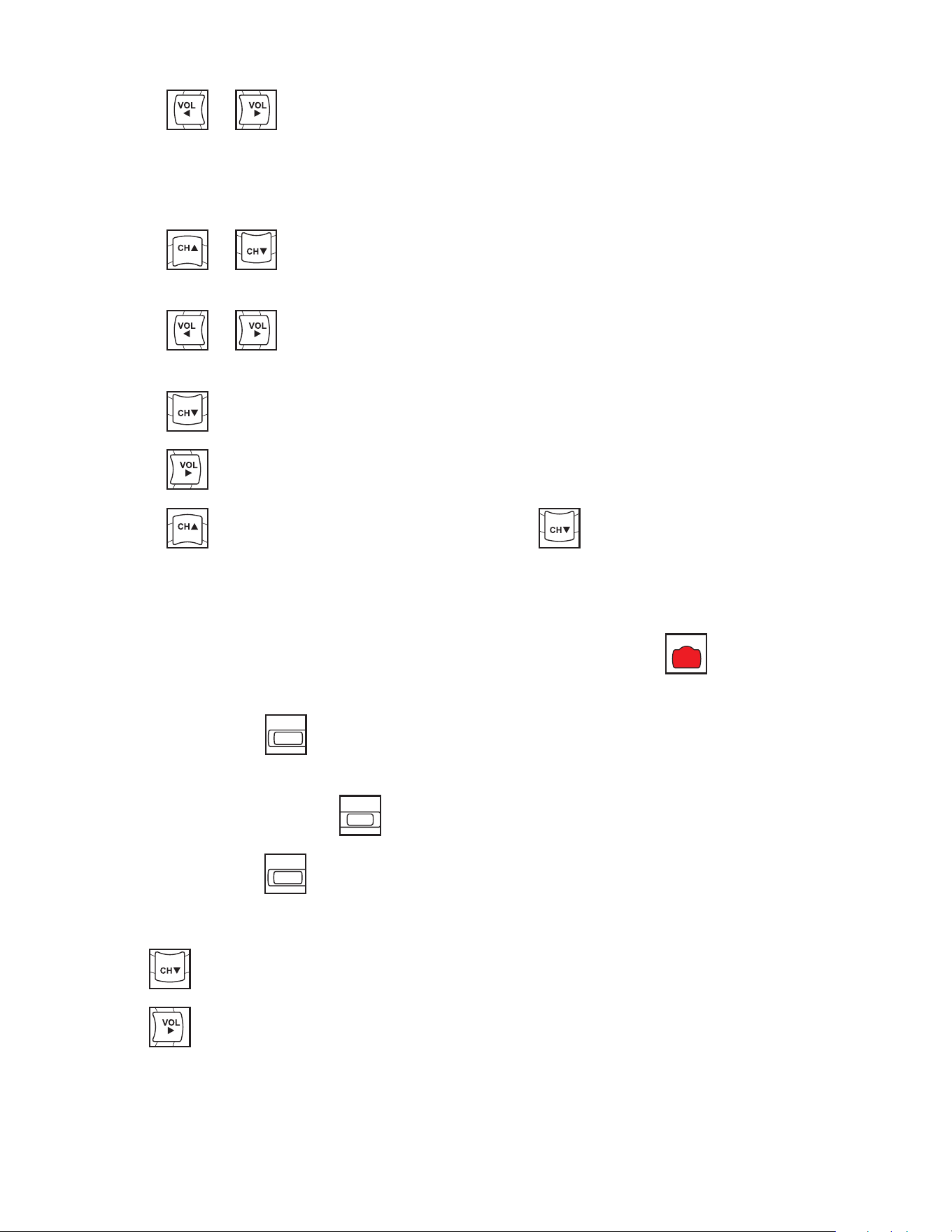
to select Mode.
ATSC Monitor
Auto Program
■ Mode Analog Only
■ Channel Sequence Interleave A + D
■ Additional Digital Signal None
■ Channel Map Programmed ►
Position: ▲ ▼
Exit: SETUP Next: ◄ ►
4. Press
POWER MUTE
SETUP TV/AV TV/FM CH LIST
SUBPAGE
HOLD MODE MIX UPDATE
TEXT SIZE INDEX REVEAL
i ?
X
PSM SSM SAP
1 2 3
4 5 6
7 8 9 0
OK
ARC CC
SLEEP LAST
or
POWER MUTE
SETUP TV/AV TV/FM CH LIST
SUBPAGE
HOLD MODE MIX UPDATE
TEXT SIZE INDEX REVEAL
i ?
X
PSM SSM SAP
1 2 3
4 5 6
7 8 9 0
OK
ARC CC
SLEEP LAST
to set the scope of channel scanning.
• Analog Only (Default): TV searches for analog channels only.
• Digital Only: TV searches for digital channels only.
• Analog and Digital: TV searches for both analog and digital channels.
5. Press
POWER MUTE
SETUP TV/AV TV/FM CH LIST
SUBPAGE
HOLD MODE MIX UPDATE
TEXT SIZE INDEX REVEAL
i ?
X
PSM SSM SAP
1 2 3
4 5 6
7 8 9 0
OK
ARC CC
SLEEP LAST
to select Channel Sequence.
Cybex Arc Trainer 625A/625AT Owner’s Manual Cybex Arc Trainer 625A/625AT Owner’s Manual
54
6. Press
POWER MUTE
SETUP TV/AV TV/FM CH LIST
SUBPAGE
HOLD MODE MIX UPDATE
TEXT SIZE INDEX REVEAL
i ?
X
PSM SSM SAP
1 2 3
4 5 6
7 8 9 0
OK
ARC CC
SLEEP LAST
or
POWER MUTE
SETUP TV/AV TV/FM CH LIST
SUBPAGE
HOLD MODE MIX UPDATE
TEXT SIZE INDEX REVEAL
i ?
X
PSM SSM SAP
1 2 3
4 5 6
7 8 9 0
OK
ARC CC
SLEEP LAST
to set the Channel Sequence in which the channels are displayed after
searching.
• Interleave A+D: In the order of channel number regardless of the system.
• All A then D: Digital channels are displayed after all analog channels.
7. Press
POWER MUTE
SETUP TV/AV TV/FM CH LIST
SUBPAGE
HOLD MODE MIX UPDATE
TEXT SIZE INDEX REVEAL
i ?
X
PSM SSM SAP
1 2 3
4 5 6
7 8 9 0
OK
ARC CC
SLEEP LAST
or
POWER MUTE
SETUP TV/AV TV/FM CH LIST
SUBPAGE
HOLD MODE MIX UPDATE
TEXT SIZE INDEX REVEAL
i ?
X
PSM SSM SAP
1 2 3
4 5 6
7 8 9 0
OK
ARC CC
SLEEP LAST
to select Additional Digital Signal. Not available when Mode is set to
Analog Only.
8. Press
POWER MUTE
SETUP TV/AV TV/FM CH LIST
SUBPAGE
HOLD MODE MIX UPDATE
TEXT SIZE INDEX REVEAL
i ?
X
PSM SSM SAP
1 2 3
4 5 6
7 8 9 0
OK
ARC CC
SLEEP LAST
or
POWER MUTE
SETUP TV/AV TV/FM CH LIST
SUBPAGE
HOLD MODE MIX UPDATE
TEXT SIZE INDEX REVEAL
i ?
X
PSM SSM SAP
1 2 3
4 5 6
7 8 9 0
OK
ARC CC
SLEEP LAST
to choose the Additional Digital Signal source. Choices are: None, Air,
Cable STD, Cable IRC, or Cable HRC.
9. Press
POWER MUTE
SETUP TV/AV TV/FM CH LIST
SUBPAGE
HOLD MODE MIX UPDATE
TEXT SIZE INDEX REVEAL
i ?
X
PSM SSM SAP
1 2 3
4 5 6
7 8 9 0
OK
ARC CC
SLEEP LAST
to select Channel Map.
10.Press
POWER MUTE
SETUP TV/AV TV/FM CH LIST
SUBPAGE
HOLD MODE MIX UPDATE
TEXT SIZE INDEX REVEAL
i ?
X
PSM SSM SAP
1 2 3
4 5 6
7 8 9 0
OK
ARC CC
SLEEP LAST
to start auto programming. A conrmation menu will appear before proceeding.
11.Press
POWER MUTE
SETUP TV/AV TV/FM CH LIST
SUBPAGE
HOLD MODE MIX UPDATE
TEXT SIZE INDEX REVEAL
i ?
X
PSM SSM SAP
1 2 3
4 5 6
7 8 9 0
OK
ARC CC
SLEEP LAST
(Yes) to start auto programming. Press
POWER MUTE
SETUP TV/AV TV/FM CH LIST
SUBPAGE
HOLD MODE MIX UPDATE
TEXT SIZE INDEX REVEAL
i ?
X
PSM SSM SAP
1 2 3
4 5 6
7 8 9 0
OK
ARC CC
SLEEP LAST
(No) button to cancel the operation.
The TV will now search all available channels with an on-screen progress percentage
displayed. Any tuning Mode that includes Digital channels will require several minutes to
complete auto programming.
This may take 20 or more minutes. If screen shuts off, Press the POWER
POWER
MUTE
SETUP TV/AV TV/FM CH LIST
SUBPAGE
HOLD MODE MIX UPDATE
TEXT SIZE INDEX REVEAL
i ?
X
PSM SSM SAP
1 2 3
4 5 6
7 8 9 0
OK
ARC CC
SLEEP LAST
button to turn monitor
on.
12.Press the SETUP
POWER MUTE
SETUP
TV/AV TV/FM CH LIST
SUBPAGE
HOLD MODE MIX UPDATE
TEXT SIZE INDEX REVEAL
i ?
X
PSM SSM SAP
1 2 3
4 5 6
7 8 9 0
OK
ARC CC
SLEEP LAST
button to return to normal TV viewing once auto programming is
complete.
13.Press the CHANNEL LIST
POWER MUTE
SETUP TV/AV TV/FM
CH LIST
SUBPAGE
HOLD MODE MIX UPDATE
TEXT SIZE INDEX REVEAL
i ?
X
PSM SSM SAP
1 2 3
4 5 6
7 8 9 0
OK
ARC CC
SLEEP LAST
button to list programmed channels.
14.Press the SETUP
POWER MUTE
SETUP
TV/AV TV/FM CH LIST
SUBPAGE
HOLD MODE MIX UPDATE
TEXT SIZE INDEX REVEAL
i ?
X
PSM SSM SAP
1 2 3
4 5 6
7 8 9 0
OK
ARC CC
SLEEP LAST
button to return to SETUP MODE menu.
Auto Program (DVB-T Monitor)
1. Tap
POWER MUTE
SETUP TV/AV TV/FM CH LIST
SUBPAGE
HOLD MODE MIX UPDATE
TEXT SIZE INDEX REVEAL
i ?
X
PSM SSM SAP
1 2 3
4 5 6
7 8 9 0
OK
ARC CC
SLEEP LAST
to select Auto Program.
2. Tap
POWER MUTE
SETUP TV/AV TV/FM CH LIST
SUBPAGE
HOLD MODE MIX UPDATE
TEXT SIZE INDEX REVEAL
i ?
X
PSM SSM SAP
1 2 3
4 5 6
7 8 9 0
OK
ARC CC
SLEEP LAST
to enter the menu.
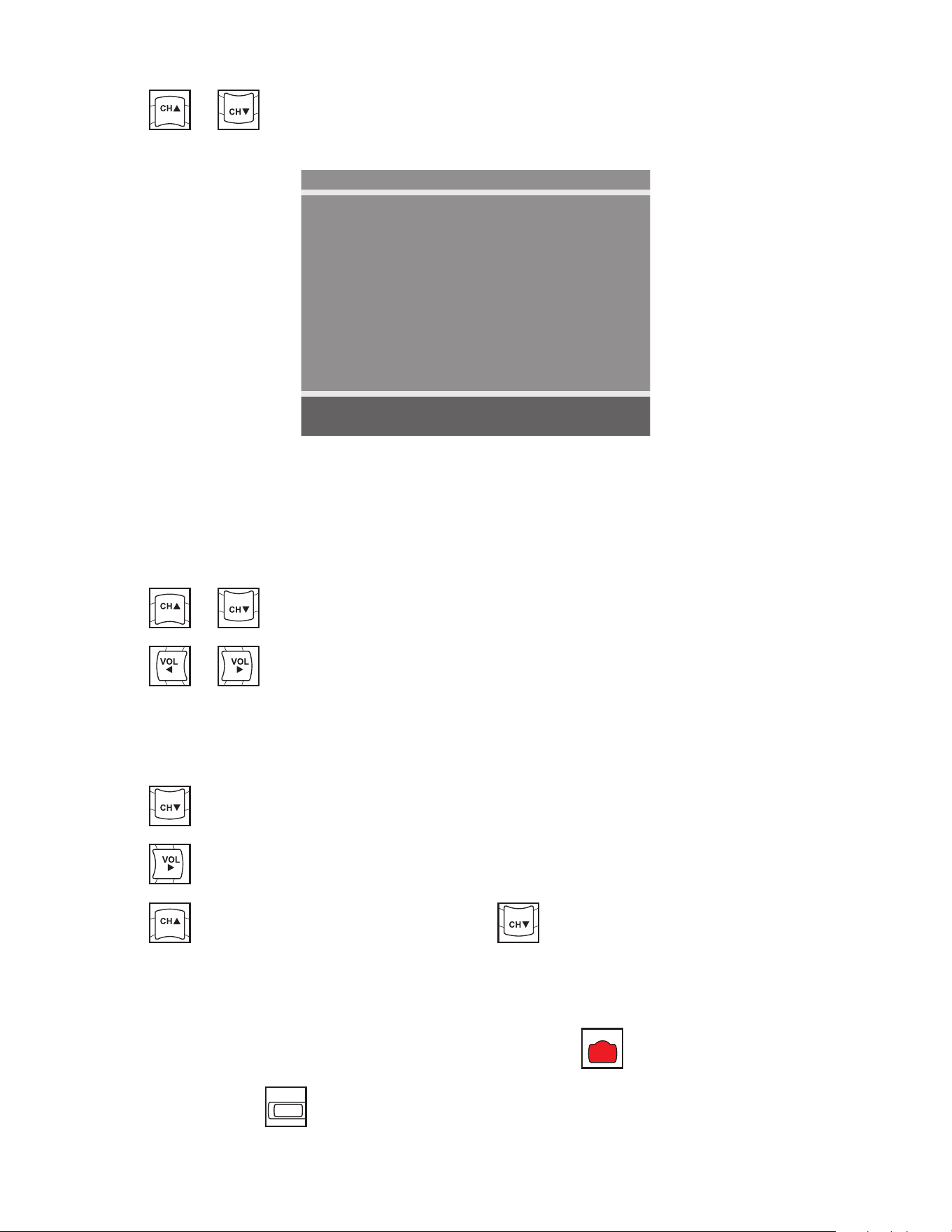
Cybex Arc Trainer 625A/625AT Owner’s Manual
55
3. Tap
POWER MUTE
SETUP TV/AV TV/FM CH LIST
SUBPAGE
HOLD MODE MIX UPDATE
TEXT SIZE INDEX REVEAL
i ?
X
PSM SSM SAP
1 2 3
4 5 6
7 8 9 0
OK
ARC CC
SLEEP LAST
or
POWER MUTE
SETUP TV/AV TV/FM CH LIST
SUBPAGE
HOLD MODE MIX UPDATE
TEXT SIZE INDEX REVEAL
i ?
X
PSM SSM SAP
1 2 3
4 5 6
7 8 9 0
OK
ARC CC
SLEEP LAST
to select Country.
DVB-T Monitor
Auto Program
■ Country ---
■ Mode Analog Only
■ Channel Map Blank ►
Position: ▲ ▼
Exit: SETUP Next: ◄ ►
Available countries are:
Albania, Austria, Australia, Belgium, Bosnia, Bulgaria, China, Croatia, Czech, Denmark, Estonia,
Finland, France, Germany, Greece, Hungary, Ireland, Italy, Kazakhstan, Latvia, Lithuania,
Luxembourg, Moroco, Netherlands, Norway, Poland, Portugal, Romania, Russia, Serbia, Slovakia,
Slovenia, Spain, Sweden, Switzerland, Turkey, Uk, and Ukraine.
4. Tap
POWER MUTE
SETUP TV/AV TV/FM CH LIST
SUBPAGE
HOLD MODE MIX UPDATE
TEXT SIZE INDEX REVEAL
i ?
X
PSM SSM SAP
1 2 3
4 5 6
7 8 9 0
OK
ARC CC
SLEEP LAST
or
POWER MUTE
SETUP TV/AV TV/FM CH LIST
SUBPAGE
HOLD MODE MIX UPDATE
TEXT SIZE INDEX REVEAL
i ?
X
PSM SSM SAP
1 2 3
4 5 6
7 8 9 0
OK
ARC CC
SLEEP LAST
to select Mode.
5. Tap
POWER MUTE
SETUP TV/AV TV/FM CH LIST
SUBPAGE
HOLD MODE MIX UPDATE
TEXT SIZE INDEX REVEAL
i ?
X
PSM SSM SAP
1 2 3
4 5 6
7 8 9 0
OK
ARC CC
SLEEP LAST
or
POWER MUTE
SETUP TV/AV TV/FM CH LIST
SUBPAGE
HOLD MODE MIX UPDATE
TEXT SIZE INDEX REVEAL
i ?
X
PSM SSM SAP
1 2 3
4 5 6
7 8 9 0
OK
ARC CC
SLEEP LAST
to set the scope of channel scanning.
• Analog Only (Default): TV searches for analog channels only.
• Digital Only: TV searches for digital channels only.
• Analog and Digital: TV searches for both analog and digital channels.
6. Tap
POWER MUTE
SETUP TV/AV TV/FM CH LIST
SUBPAGE
HOLD MODE MIX UPDATE
TEXT SIZE INDEX REVEAL
i ?
X
PSM SSM SAP
1 2 3
4 5 6
7 8 9 0
OK
ARC CC
SLEEP LAST
to select Channel Map.
7. Tap
POWER MUTE
SETUP TV/AV TV/FM CH LIST
SUBPAGE
HOLD MODE MIX UPDATE
TEXT SIZE INDEX REVEAL
i ?
X
PSM SSM SAP
1 2 3
4 5 6
7 8 9 0
OK
ARC CC
SLEEP LAST
to start auto programming. A conrmation menu will appear before proceeding.
8. Tap
POWER MUTE
SETUP TV/AV TV/FM CH LIST
SUBPAGE
HOLD MODE MIX UPDATE
TEXT SIZE INDEX REVEAL
i ?
X
PSM SSM SAP
1 2 3
4 5 6
7 8 9 0
OK
ARC CC
SLEEP LAST
(Yes) to start auto programming. Tap
POWER MUTE
SETUP TV/AV TV/FM CH LIST
SUBPAGE
HOLD MODE MIX UPDATE
TEXT SIZE INDEX REVEAL
i ?
X
PSM SSM SAP
1 2 3
4 5 6
7 8 9 0
OK
ARC CC
SLEEP LAST
(No) button to cancel the operation. The
TV will now search all available channels with an on-screen progress percentage displayed.
Any tuning Mode that includes Digital channels will require several minutes to complete auto
programming.
This may take 20 or more minutes. If screen shuts off, POWER
POWER
MUTE
SETUP TV/AV TV/FM CH LIST
SUBPAGE
HOLD MODE MIX UPDATE
TEXT SIZE INDEX REVEAL
i ?
X
PSM SSM SAP
1 2 3
4 5 6
7 8 9 0
OK
ARC CC
SLEEP LAST
button to turn monitor on.
9. Press the SETUP
POWER MUTE
SETUP
TV/AV TV/FM CH LIST
SUBPAGE
HOLD MODE MIX UPDATE
TEXT SIZE INDEX REVEAL
i ?
X
PSM SSM SAP
1 2 3
4 5 6
7 8 9 0
OK
ARC CC
SLEEP LAST
button to return to normal TV viewing once auto programming is
complete.
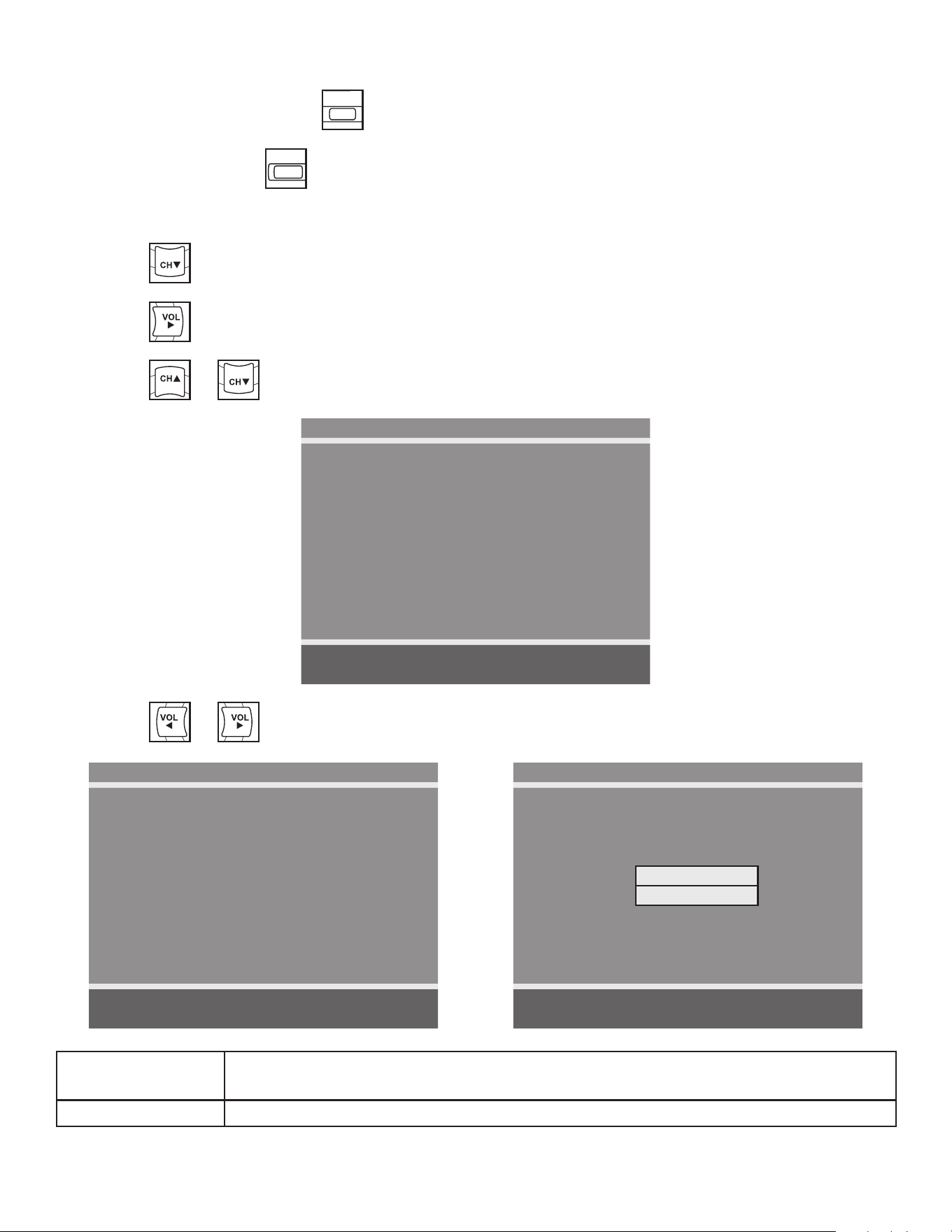
Cybex Arc Trainer 625A/625AT Owner’s Manual Cybex Arc Trainer 625A/625AT Owner’s Manual
56
10.Tap the CHANNEL LIST
POWER MUTE
SETUP TV/AV TV/FM
CH LIST
SUBPAGE
HOLD MODE MIX UPDATE
TEXT SIZE INDEX REVEAL
i ?
X
PSM SSM SAP
1 2 3
4 5 6
7 8 9 0
OK
ARC CC
SLEEP LAST
button to list programmed channels.
11.Press the SETUP
POWER MUTE
SETUP
TV/AV TV/FM CH LIST
SUBPAGE
HOLD MODE MIX UPDATE
TEXT SIZE INDEX REVEAL
i ?
X
PSM SSM SAP
1 2 3
4 5 6
7 8 9 0
OK
ARC CC
SLEEP LAST
button to return to SETUP MODE menu.
Manual Program (ATSC and DVB-T)
1. Tap
POWER MUTE
SETUP TV/AV TV/FM CH LIST
SUBPAGE
HOLD MODE MIX UPDATE
TEXT SIZE INDEX REVEAL
i ?
X
PSM SSM SAP
1 2 3
4 5 6
7 8 9 0
OK
ARC CC
SLEEP LAST
to select Manual Program.
2. Tap
POWER MUTE
SETUP TV/AV TV/FM CH LIST
SUBPAGE
HOLD MODE MIX UPDATE
TEXT SIZE INDEX REVEAL
i ?
X
PSM SSM SAP
1 2 3
4 5 6
7 8 9 0
OK
ARC CC
SLEEP LAST
to enter the menu.
3. Tap
POWER MUTE
SETUP TV/AV TV/FM CH LIST
SUBPAGE
HOLD MODE MIX UPDATE
TEXT SIZE INDEX REVEAL
i ?
X
PSM SSM SAP
1 2 3
4 5 6
7 8 9 0
OK
ARC CC
SLEEP LAST
or
POWER MUTE
SETUP TV/AV TV/FM CH LIST
SUBPAGE
HOLD MODE MIX UPDATE
TEXT SIZE INDEX REVEAL
i ?
X
PSM SSM SAP
1 2 3
4 5 6
7 8 9 0
OK
ARC CC
SLEEP LAST
to select Mode.
Manual Program
■ Mode ATV
■ Conrmation ►
Position: ▲ ▼
Exit: SETUP Next: ◄ ►
4. Tap
POWER MUTE
SETUP TV/AV TV/FM CH LIST
SUBPAGE
HOLD MODE MIX UPDATE
TEXT SIZE INDEX REVEAL
i ?
X
PSM SSM SAP
1 2 3
4 5 6
7 8 9 0
OK
ARC CC
SLEEP LAST
or
POWER MUTE
SETUP TV/AV TV/FM CH LIST
SUBPAGE
HOLD MODE MIX UPDATE
TEXT SIZE INDEX REVEAL
i ?
X
PSM SSM SAP
1 2 3
4 5 6
7 8 9 0
OK
ARC CC
SLEEP LAST
to select ATV or DTV.
ATV Manual Program
■ Storage 1
■ System BG
■ Band V/UHF
■ Channel 1
■ Name C 01
■ Search ◄ ►
■ Save ►
Position: ▲ ▼
Exit: SETUP Next: ◄ ►
DTV Manual Program
■ UHF CH. ►
■ Save 21
Bad Nor. Good
Signal Strength
Signal Quality
Position: ▲ ▼
Exit: SETUP Next: ◄ ►
ATV Mode Adjust settings for Storage, System, Band, Channel, Name, or Search. Select
Save to save settings.
DTV Mode Select UHF channel. Select Save to save settings.
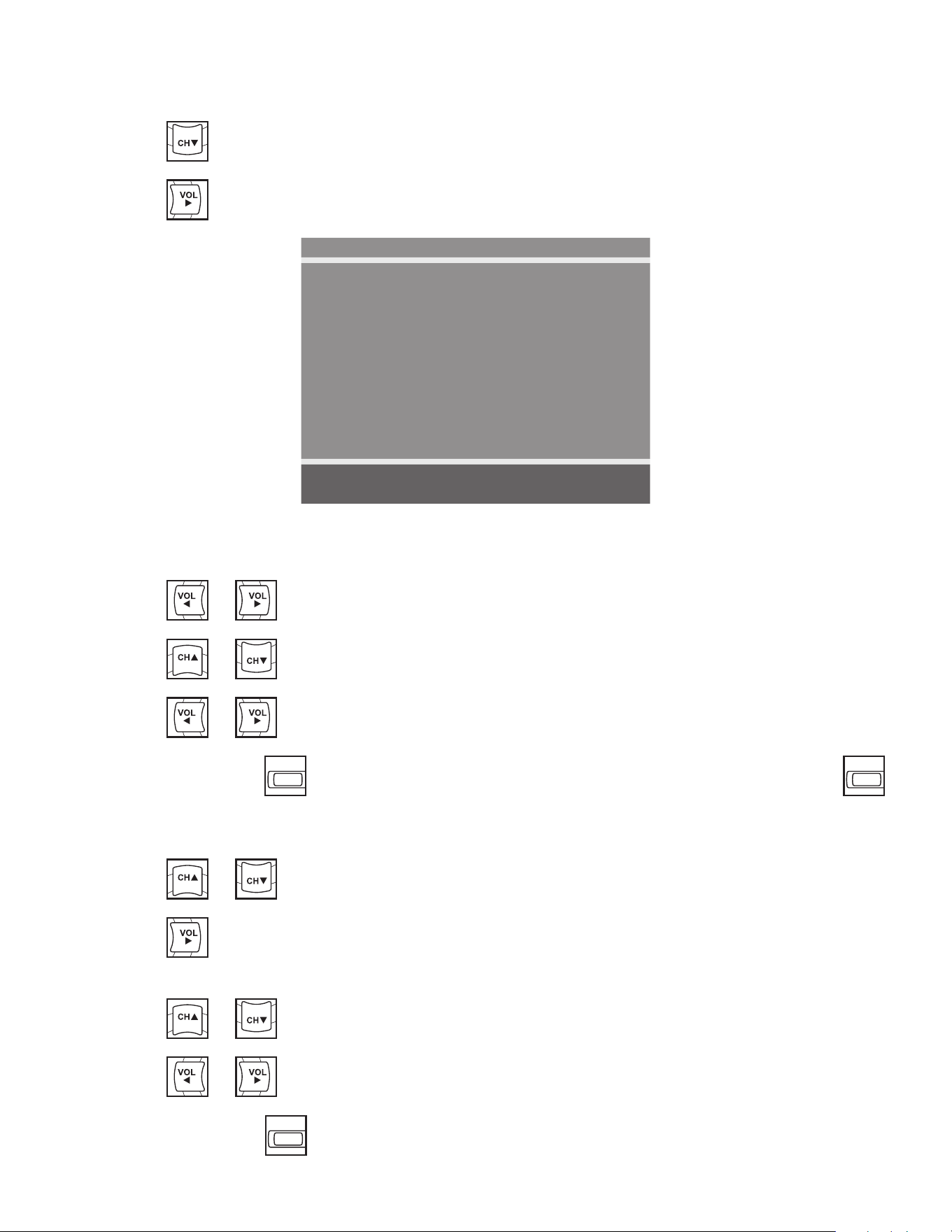
Cybex Arc Trainer 625A/625AT Owner’s Manual
57
Add/Delete Channels (ATSC and DVB-T)
1. Press
POWER MUTE
SETUP TV/AV TV/FM CH LIST
SUBPAGE
HOLD MODE MIX UPDATE
TEXT SIZE INDEX REVEAL
i ?
X
PSM SSM SAP
1 2 3
4 5 6
7 8 9 0
OK
ARC CC
SLEEP LAST
to select Add/Delete Channels.
2. Press
POWER MUTE
SETUP TV/AV TV/FM CH LIST
SUBPAGE
HOLD MODE MIX UPDATE
TEXT SIZE INDEX REVEAL
i ?
X
PSM SSM SAP
1 2 3
4 5 6
7 8 9 0
OK
ARC CC
SLEEP LAST
to enter the Add/Delete Channels menu.
Add/Delete Channels
■ Analog Channel 2
■ Add/Delete Analog Channel Added
■ Enable/Disable Digital Channel ►
Position: ▲ ▼
Exit: SETUP Next: ◄ ►
To add or delete an analog channel perform the following procedure. To enable or disable digital
channels, go to step 7.
3. Press
POWER MUTE
SETUP TV/AV TV/FM CH LIST
SUBPAGE
HOLD MODE MIX UPDATE
TEXT SIZE INDEX REVEAL
i ?
X
PSM SSM SAP
1 2 3
4 5 6
7 8 9 0
OK
ARC CC
SLEEP LAST
or
POWER MUTE
SETUP TV/AV TV/FM CH LIST
SUBPAGE
HOLD MODE MIX UPDATE
TEXT SIZE INDEX REVEAL
i ?
X
PSM SSM SAP
1 2 3
4 5 6
7 8 9 0
OK
ARC CC
SLEEP LAST
to select the desired analog channel.
4. Press
POWER MUTE
SETUP TV/AV TV/FM CH LIST
SUBPAGE
HOLD MODE MIX UPDATE
TEXT SIZE INDEX REVEAL
i ?
X
PSM SSM SAP
1 2 3
4 5 6
7 8 9 0
OK
ARC CC
SLEEP LAST
or
POWER MUTE
SETUP TV/AV TV/FM CH LIST
SUBPAGE
HOLD MODE MIX UPDATE
TEXT SIZE INDEX REVEAL
i ?
X
PSM SSM SAP
1 2 3
4 5 6
7 8 9 0
OK
ARC CC
SLEEP LAST
to highlight Add/Delete Analog Channel.
5. Press
POWER MUTE
SETUP TV/AV TV/FM CH LIST
SUBPAGE
HOLD MODE MIX UPDATE
TEXT SIZE INDEX REVEAL
i ?
X
PSM SSM SAP
1 2 3
4 5 6
7 8 9 0
OK
ARC CC
SLEEP LAST
or
POWER MUTE
SETUP TV/AV TV/FM CH LIST
SUBPAGE
HOLD MODE MIX UPDATE
TEXT SIZE INDEX REVEAL
i ?
X
PSM SSM SAP
1 2 3
4 5 6
7 8 9 0
OK
ARC CC
SLEEP LAST
to select Added or Deleted.
6. Press the SETUP
POWER MUTE
SETUP
TV/AV TV/FM CH LIST
SUBPAGE
HOLD MODE MIX UPDATE
TEXT SIZE INDEX REVEAL
i ?
X
PSM SSM SAP
1 2 3
4 5 6
7 8 9 0
OK
ARC CC
SLEEP LAST
button to return to the previous menu. To exit, Press the SETUP
POWER MUTE
SETUP
TV/AV TV/FM CH LIST
SUBPAGE
HOLD MODE MIX UPDATE
TEXT SIZE INDEX REVEAL
i ?
X
PSM SSM SAP
1 2 3
4 5 6
7 8 9 0
OK
ARC CC
SLEEP LAST
button until the programming menus disappear. If there are more analog channels to be added
or deleted, repeat steps 3 through 5.
7. Press
POWER MUTE
SETUP TV/AV TV/FM CH LIST
SUBPAGE
HOLD MODE MIX UPDATE
TEXT SIZE INDEX REVEAL
i ?
X
PSM SSM SAP
1 2 3
4 5 6
7 8 9 0
OK
ARC CC
SLEEP LAST
or
POWER MUTE
SETUP TV/AV TV/FM CH LIST
SUBPAGE
HOLD MODE MIX UPDATE
TEXT SIZE INDEX REVEAL
i ?
X
PSM SSM SAP
1 2 3
4 5 6
7 8 9 0
OK
ARC CC
SLEEP LAST
to highlight Enable/Disable Digital Channel.
8. Press
POWER MUTE
SETUP TV/AV TV/FM CH LIST
SUBPAGE
HOLD MODE MIX UPDATE
TEXT SIZE INDEX REVEAL
i ?
X
PSM SSM SAP
1 2 3
4 5 6
7 8 9 0
OK
ARC CC
SLEEP LAST
to select Enable/Disable Digital Channel. If there are not any channels
programmed in the Service Level, “No Channels Present” will appear in the menu.
9. Press
POWER MUTE
SETUP TV/AV TV/FM CH LIST
SUBPAGE
HOLD MODE MIX UPDATE
TEXT SIZE INDEX REVEAL
i ?
X
PSM SSM SAP
1 2 3
4 5 6
7 8 9 0
OK
ARC CC
SLEEP LAST
or
POWER MUTE
SETUP TV/AV TV/FM CH LIST
SUBPAGE
HOLD MODE MIX UPDATE
TEXT SIZE INDEX REVEAL
i ?
X
PSM SSM SAP
1 2 3
4 5 6
7 8 9 0
OK
ARC CC
SLEEP LAST
to highlight the digital channel that needs to be enabled or disabled.
10.Press
POWER MUTE
SETUP TV/AV TV/FM CH LIST
SUBPAGE
HOLD MODE MIX UPDATE
TEXT SIZE INDEX REVEAL
i ?
X
PSM SSM SAP
1 2 3
4 5 6
7 8 9 0
OK
ARC CC
SLEEP LAST
or
POWER MUTE
SETUP TV/AV TV/FM CH LIST
SUBPAGE
HOLD MODE MIX UPDATE
TEXT SIZE INDEX REVEAL
i ?
X
PSM SSM SAP
1 2 3
4 5 6
7 8 9 0
OK
ARC CC
SLEEP LAST
to select Enable or Disable.
11.Press the SETUP
POWER MUTE
SETUP
TV/AV TV/FM CH LIST
SUBPAGE
HOLD MODE MIX UPDATE
TEXT SIZE INDEX REVEAL
i ?
X
PSM SSM SAP
1 2 3
4 5 6
7 8 9 0
OK
ARC CC
SLEEP LAST
button to return to the previous menu.
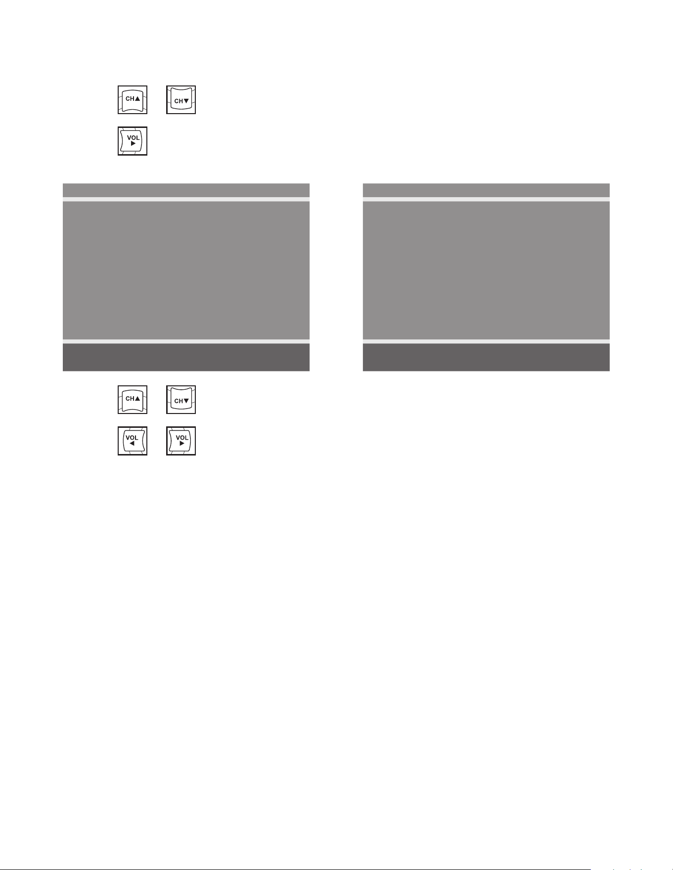
Cybex Arc Trainer 625A/625AT Owner’s Manual Cybex Arc Trainer 625A/625AT Owner’s Manual
58
Features
1. Press
POWER MUTE
SETUP TV/AV TV/FM CH LIST
SUBPAGE
HOLD MODE MIX UPDATE
TEXT SIZE INDEX REVEAL
i ?
X
PSM SSM SAP
1 2 3
4 5 6
7 8 9 0
OK
ARC CC
SLEEP LAST
or
POWER MUTE
SETUP TV/AV TV/FM CH LIST
SUBPAGE
HOLD MODE MIX UPDATE
TEXT SIZE INDEX REVEAL
i ?
X
PSM SSM SAP
1 2 3
4 5 6
7 8 9 0
OK
ARC CC
SLEEP LAST
to select Features.
2. Press
POWER MUTE
SETUP TV/AV TV/FM CH LIST
SUBPAGE
HOLD MODE MIX UPDATE
TEXT SIZE INDEX REVEAL
i ?
X
PSM SSM SAP
1 2 3
4 5 6
7 8 9 0
OK
ARC CC
SLEEP LAST
to select access Features menu.
ATSC Monitor
Features
■ Power on Captions Mode Last
■ Digital Mode Time Setup ►
■ Diagnostics ►
■ Caption Text Modes Disabled
Position: ▲ ▼
Exit: SETUP Next: ◄ ►
DVB-T Monitor
Features
■ Power on Subtitles Mode Last
■ Digital Mode Time Setup ►
■ Diagnostics ►
Position: ▲ ▼
Exit: SETUP Next: ◄ ►
3. Press
POWER MUTE
SETUP TV/AV TV/FM CH LIST
SUBPAGE
HOLD MODE MIX UPDATE
TEXT SIZE INDEX REVEAL
i ?
X
PSM SSM SAP
1 2 3
4 5 6
7 8 9 0
OK
ARC CC
SLEEP LAST
or
POWER MUTE
SETUP TV/AV TV/FM CH LIST
SUBPAGE
HOLD MODE MIX UPDATE
TEXT SIZE INDEX REVEAL
i ?
X
PSM SSM SAP
1 2 3
4 5 6
7 8 9 0
OK
ARC CC
SLEEP LAST
to select settings.
4. Press
POWER MUTE
SETUP TV/AV TV/FM CH LIST
SUBPAGE
HOLD MODE MIX UPDATE
TEXT SIZE INDEX REVEAL
i ?
X
PSM SSM SAP
1 2 3
4 5 6
7 8 9 0
OK
ARC CC
SLEEP LAST
or
POWER MUTE
SETUP TV/AV TV/FM CH LIST
SUBPAGE
HOLD MODE MIX UPDATE
TEXT SIZE INDEX REVEAL
i ?
X
PSM SSM SAP
1 2 3
4 5 6
7 8 9 0
OK
ARC CC
SLEEP LAST
to adjust settings.

Cybex Arc Trainer 625A/625AT Owner’s Manual
59
Testing Operation
Use the following instructions to test the full resistance and incline range of the unit:
1. Plug the optional power cord into a power outlet from a grounded circuit, See Electrical
Requirements. Coil up the remainder of the power cord and place it out of the way. If you do
not have the optional power supply, skip to step 3.
2. Verify the control panel will illuminate and is in Dormant Mode.
3. Hold the handrails to steady self while stepping into the foot plates.
4. Begin striding.
5. Tap Quick Start.
6. Run unit through full resistance range. First press the RESISTANCE + key until unit reaches
its highest load (the display will show “100”). Then press the RESISTANCE - key until unit
reaches its lowest load (the display will show “0”). The resistance should increase and
decrease while striding.
When unit reaches the set incline and resistance, the displays will stop ashing and remain steadily
illuminated to indicate the desired settings have been reached.
7. Run unit through full incline range. First press the INCLINE key until the unit reaches its
highest incline (the display will show “20”). Then press the INCLINE key until unit reaches its
lowest incline (the display will show “0”). The foot plates and arms should move freely during
all incline levels.
WARNING: Serious injury or death can occur. To avoid death or injury the following
precautions must be observed. Wait until all moving parts come to a complete
stop before dismounting. Failure to wait for complete stop can trip or injure
user.
8. Press the Pause key twice to bring the incline back to its start position, end the workout
review, and return the display to Dormant Mode.
9. Wait until foot plates come to a complete stop before dismounting unit. Hold handrails to
steady self while stepping off unit.

Cybex Arc Trainer 625A/625AT Owner’s Manual Cybex Arc Trainer 625A/625AT Owner’s Manual
60
Operation
Intended Use
Intended use of this exercise equipment is to aid or improve general physical tness and exercise.
Terms Used
Active Mode – Any time the unit is controlling resistance and accumulating workout data. Active
Mode begins after pressing the Quick Start key, after completing the setup for a
program, or by default if the initial screen times out and enters Quick Start Manual
mode.
Auto-Scan – Display automatically cycles through workout data.
Cool Down – A reduction of work load for a short duration allows user to gently reduce heart rate.
Cool Down occurs two minutes prior to completion of the program-controlled workout
sessions.
Dormant Mode – Occurs when unit is plugged in with optional AC adapter and not in use.
Manual Mode – Manual Mode allows the user to adjust the Incline (0-20) and Resistance (0-100).
Pause Mode – Occurs only if the Pause feature is enabled and user selects the PAUSE key from
Active Mode.
Quick Start – Press the QUICK START key to enter into Quick Start Manual Mode, where the user
controls the Incline and Resistance as time counts up. Also occurs after 20 seconds of the user
striding and not interacting with the console.
Workout Review – Review of the accumulated workout data will happen at the end of each workout
session.
Read and understand all warnings and cautions in the Safety Section and all operation
instructions in this chapter before operating unit.
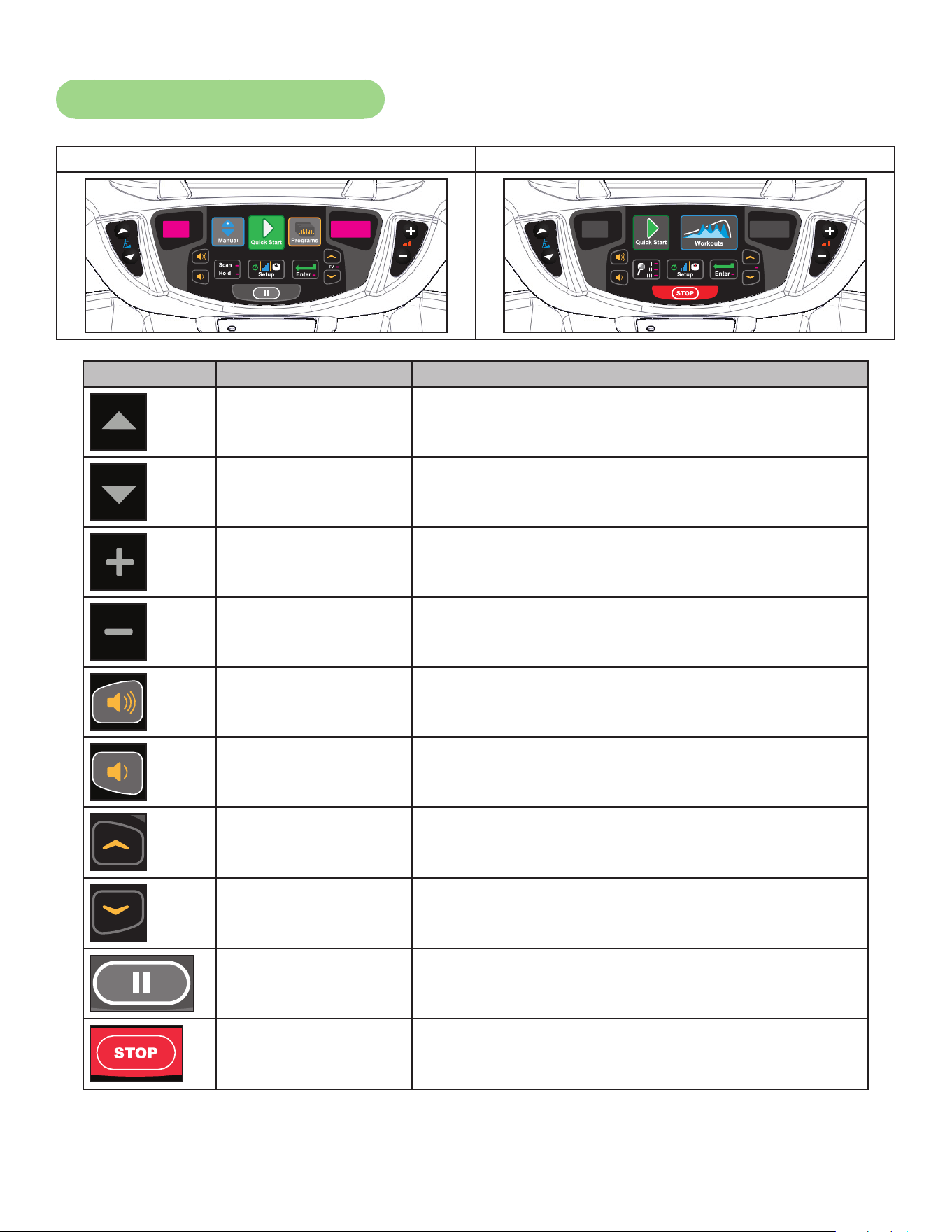
Cybex Arc Trainer 625A/625AT Owner’s Manual
61
User Control Symbols Used
Membrane with Progams key Membrane with Workouts key
Control Control Name Description
INCLINE UP Adjust Incline up.
INCLINE DOWN Adjust Incline down.
RESISTANCE UP Adjust Resistance up.
RESISTANCE DOWN Adjust Resistance down.
VOLUME UP Adjust Volume up.
VOLUME DOWN Adjust Volume down.
UP KEY
Adjust Time, Level, Weight, or Program up.
A/V - Channel UP.
iPod/iPhone/iPad - NEXT track (option)
DOWN KEY
Adjust Time, Level, Weight, or Program down.
A/V - Channel DOWN.
iPod/iPhone/iPad - PREVIOUS track (option)
PAUSE
If pause feature is enabled, press Pause once to
enter pause mode.
STOP
Press STOP once to end the workout session and
start the Workout Review. Press STOP again to exit
to Dormant Mode.
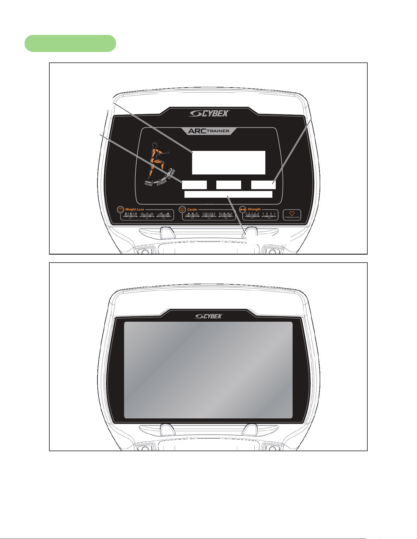
Cybex Arc Trainer 625A/625AT Owner’s Manual Cybex Arc Trainer 625A/625AT Owner’s Manual
62
Console Display
®
Bar Graph
Data
Readouts
Enunciator
Heart Rate
Indicator
LED Display
E3 View Monitor
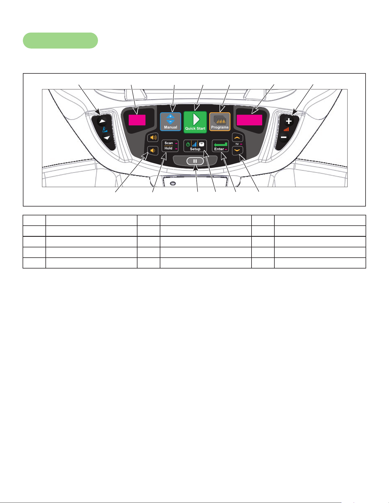
Cybex Arc Trainer 625A/625AT Owner’s Manual
63
User Controls
Membrane with Progams key
1 2 3 54 6 7
9 1110 12 138
1 Incline keys 6 Resistance display 11 Setup key
2 Incline display 7 Resistance keys 12 Enter key
3 Manual key 8 Volume keys 13 Up/Down keys
4 Quick Start key 9 Scan/Hold key
5 Programs key 10 Pause key
Displays — Incline and Resistance are shown in the LED displays. The TV LED indicates when Up/
Down keys are active to change channels.
Keys — User controls for Incline, Manual, Quick Start, Programs, Resistance, Volume, Scan/Hold,
Pause, Setup, Enter and Up/Down.
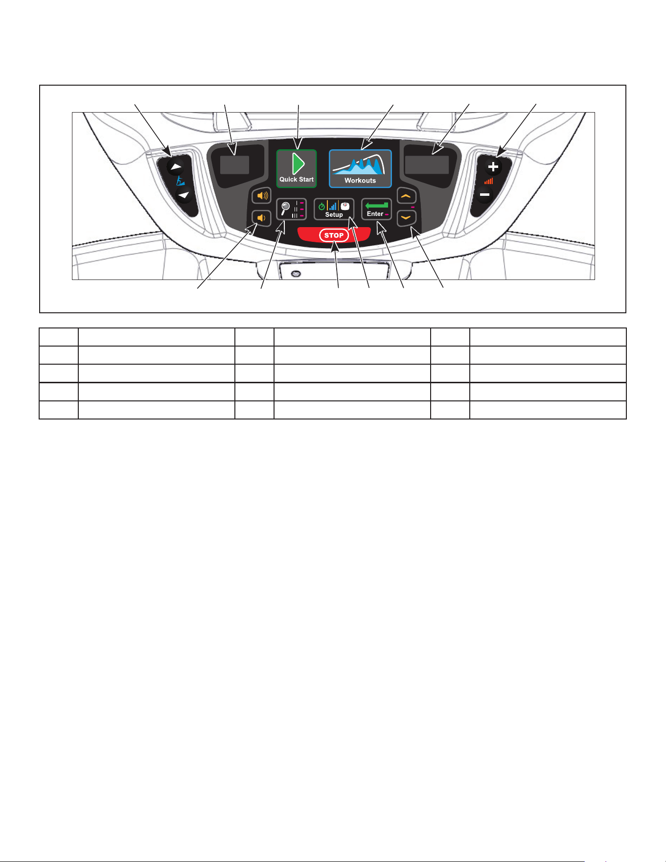
Cybex Arc Trainer 625A/625AT Owner’s Manual Cybex Arc Trainer 625A/625AT Owner’s Manual
64
Membrane with Workouts key
1 2 3 4 5 6
8 109 11 127
1 Incline keys 6 Resistance keys 11 Enter key
2 Incline display 7 Volume keys 12 Up/Down keys
3 Quick Start key 8 Display option key
4 Workouts key 9 STOP key
5 Resistance display 10 Setup key
Displays — Incline and Resistance are shown in the LED displays. The TV LED indicates when Up/
Down keys are active to change channels.
Keys — User controls for Incline, Quick Start, Workouts, Resistance, Volume, Display option, STOP,
Setup, Enter and Up/Down.

Cybex Arc Trainer 625A/625AT Owner’s Manual
65
Mount and Dismount
WARNING: Serious injury or death can occur. To avoid death or injury the following
precautions must be observed. Wait until all moving parts come to a complete
stop and foot plates are in starting position before mounting or dismounting.
Mounting or dismounting while foot plates are moving can trip or injure user.
To mount unit safely:
1. Verify unit is off or in Dormant Mode and foot plates are completely stopped.
2. Grasp handrail and step carefully onto foot plates.
To dismount unit safely:
1. Wait until foot plates come to a complete stop.
2. Grasp handrails for support and carefully step off back of unit.
Emergency Dismount
If an emergency stop and dismount is required:
1. Grasp handrails for support.
2. Stop striding.
3. Wait until foot plates come to a complete stop.
4. Continue to hold handrails while carefully stepping off unit.
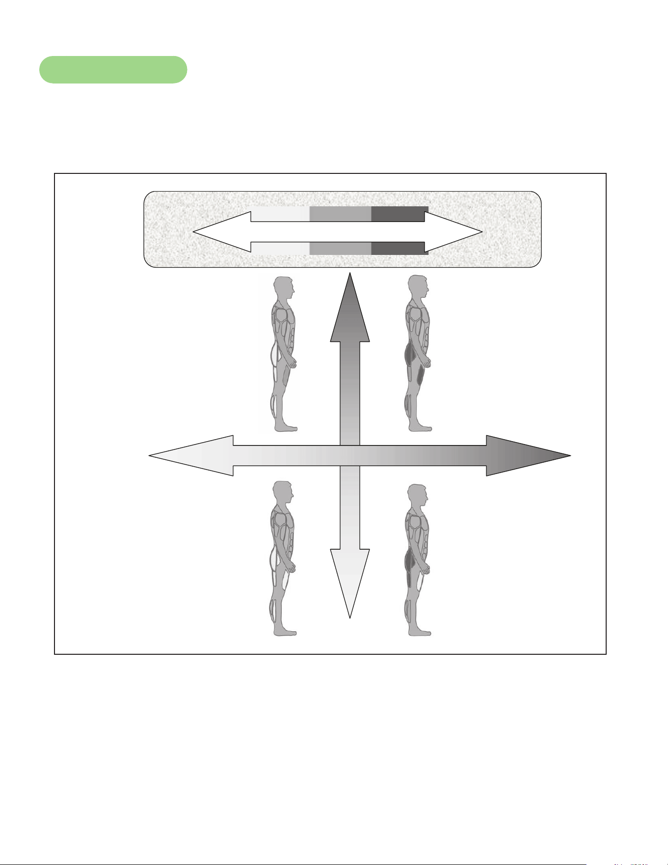
Cybex Arc Trainer 625A/625AT Owner’s Manual Cybex Arc Trainer 625A/625AT Owner’s Manual
66
Range of Motion
The elevation is adjustable up or down in the shape of an arc. The lowest setting of 0 equates to an
arc of 12 degrees, where the highest setting of 20 equates to an arc of 34.5 degrees. There is no
difference in muscles used between different incline positions. Differences exist in the intensity of
muscle activity.
Incline
Resistance
Intensity
High
Low
High
HighLow
Low

Cybex Arc Trainer 625A/625AT Owner’s Manual
67
Quick Operation Guide
Maximum user weight is 400 lbs. (181 kg).
The following is a quick overview of the operation of the unit. For more information read Detailed
Operation Guide in this chapter.
1. Verify foot plates are completely stopped.
2. Grasp handrail and step carefully onto foot plates. Begin striding.
3. Press the Quick Start key. The console will beep for one second and display “GO!”.
4. Press the Incline ▲▼ keys to change the incline at any time. The left display will show incline.
5. Press the Resistance + – keys to change the resistance at any time. The right display will
show the current resistance.
6. Press the Pause key at any time to pause. “Workout Review” is displayed, if pause is enabled,
and the incline returns to 6%.
Detailed Operation Guide
Maximum user weight is 400 lbs. (181 kg).
1. Plug the optional power cord into a power outlet from a grounded circuit, See Electrical
Requirements. Coil up the remainder of the power cord and place it out of the way. The
control panel will light up and be in the Dormant Mode.
2. Verify foot plates are completely stopped.
3. Grasp handrail and step carefully onto foot plates. Begin striding.
4. Select Manual, Quick Start or Programs.
If Manual is selected, enter Time then Weight.
1. Adjust time with the UP
and DOWN keys.
2. Press the ENTER
key to advance to weight settings.
3. Adjust weight with the UP and DOWN keys. For the most accurate resistance and
calorie count, you must set your correct weight before beginning your workout (including
clothing).
4. Press the ENTER
key to advance to weight settings.The console will beep for one
second and display “GO!”, and enter Active Mode.
If Quick Start is selected, The console will beep for one second, display “GO!”, and enter Active
Mode.
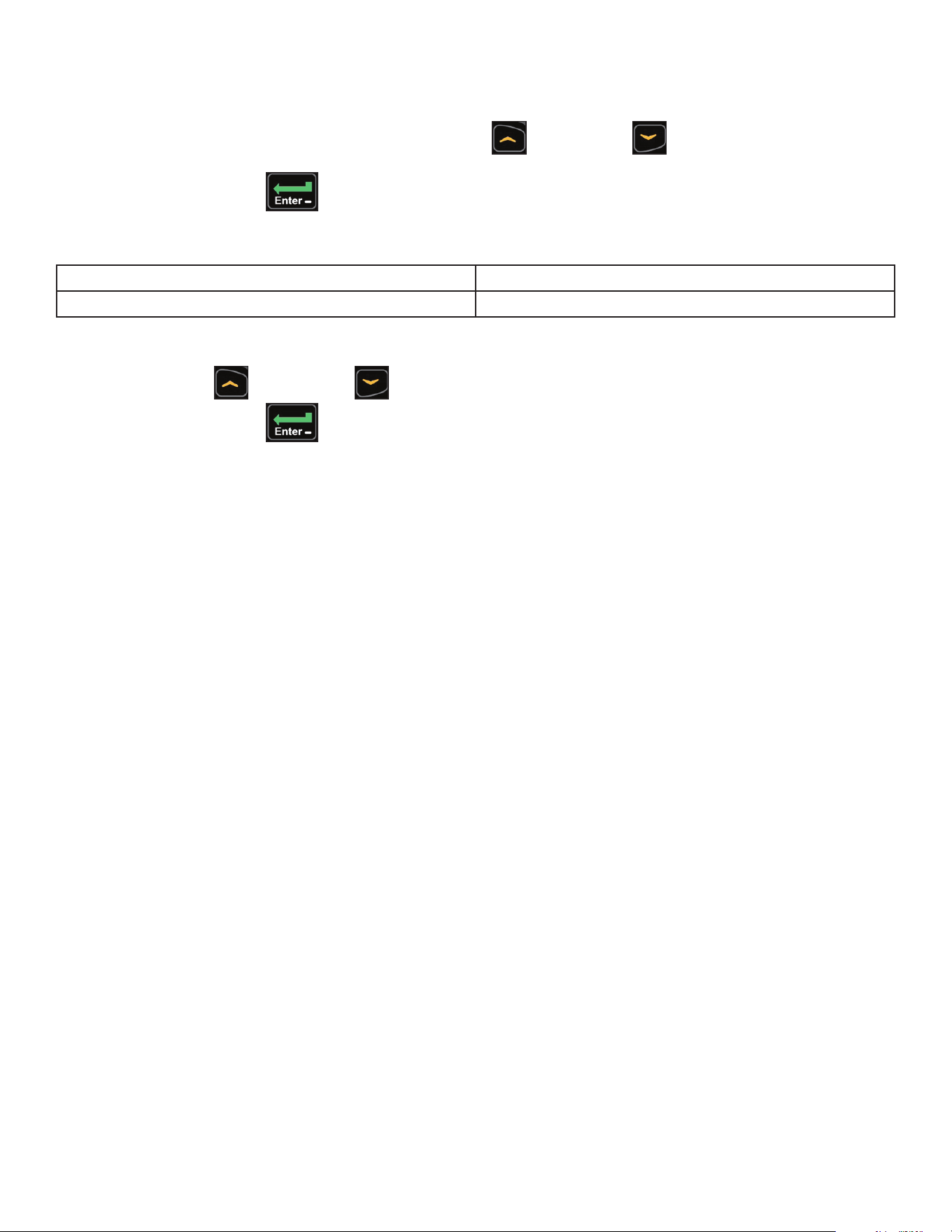
Cybex Arc Trainer 625A/625AT Owner’s Manual Cybex Arc Trainer 625A/625AT Owner’s Manual
68
If Programs is selected, Select a program and setup options.
1. Select programs P-1 through P-9 with the UP
and DOWN keys.
2. Press the ENTER key to advance to setup options.
Setup options:
Programs P-1 through P-8 Time, Level, Weight
Heart Rate Control P-9* Time, Weight, Age, Target Heart Rate
*The Heart Rate Control program requires wearing a Polar® compatible chest strap (not included).
3. Use the UP
and DOWN keys to increase or descrease each of the setup options.
Press the ENTER key to advance to the next option.
For the most accurate resistance and calorie count, you must set your correct weight before
beginning your workout (including clothing).
When selecting a program you must press the Enter key after each adjustment of Time, Level,
Weight, Age, or Target Heart Rate.
After nal selection has been made the console will beep for one second, display “GO!”, and enter
Active Mode.
4. Begin striding.
5. Observe the control panel. The top center Bar Graph display shows a graphical representation
of the relative MET level, and if in a program, will show the relative intensity changes that are
coming up. The Data Readouts will start showing the workout data such as Distance, Calories,
Heart rate (if available), METs and Time. The data displays will start by automatically shifting
every 5 seconds.
Heart rate will be displayed in lieu of METs if a valid heart rate is available from a wireless chest strap
(not included) or by holding the contact heart rate grips.
When you adjust incline or resistance in a program, the change will affect only the current segment.
The program control will resume starting with the next segment. To increase or decrease overall
intensity, adjust the resistance and/or the program level.
6. Press the Incline ▲▼ keys to change the incline at any time. The left display will show incline.
7. Press the Resistance + – keys to change the resistance at any time. The right display will
show the current resistance.
8. Press the Pause key at any time to pause. “Workout Review” is displayed, if pause is disabled,
and the incline returns to 6%.
When a program is complete the unit begins a countdown, “3...2...1” and sounds a tone for each
count. Workout Review is displayed for the preset time or until you press the Pause key. The unit
returns to Dormant Mode.
Cybex Arc Trainer 625A/625AT Owner’s Manual
69
Program Selection
WARNING: Serious injury or death can occur. To avoid death or injury the following
precautions must be observed. Obtain a medical exam before beginning any
exercise program. Begin comfortably with a lower level and progress with
higher levels as you become acclimated.
With the 625A and 625AT you may choose from Quick Start, Manual Mode, or nine program choices.
Speed is never predetermined. Change speed by changing stride.
Manual Choices:
• Quick Start Press Quick Start. Control incline and resistance.
• Manual Mode Set a Time goal. Enter weight. Control incline and resistance.
Program Choices:
Program Levels Settings
P1 Weight Loss 1 10 Select time, level and weight.
P2 Weight Loss 2 10 Select time, level and weight.
P3 Weight Loss 3 10 Select time, level and weight.
P4 Cardio 1 10 Select time, level and weight.
P5 Cardio 2 10 Select time, level and weight.
P6 Cardio 3 10 Select time, level and weight.
P7 Strength 1 10 Select time, level and weight.
P8 Strength 2 10 Select time, level and weight.
P9 Heart rate Control (HRC) N/A Select time, age, target heart rate and weight.
See Appendix for Program Overviews

Cybex Arc Trainer 625A/625AT Owner’s Manual Cybex Arc Trainer 625A/625AT Owner’s Manual
70
Data Readouts
As the user exercises, the unit keeps track of and displays the following data:
BPM (Beats Per Minute) – User’s current heart rate. Heart rate will appear when a signal is
introduced.
Calories – The total accumulated calories burned during workout.
Calories Per Hour – Calculation of present workload’s energy exertion in Calories per Hour.
Distance – The total accumulated distance during workout. Depending on the defaults chosen, this
measurement will show in English (miles) or Metric (kilometers). The unit uses a xed 24”
(61 cm) stroke, giving a travel distance of 48” (122 cm) per revolution. Distance = Strides
per Minute x 24” (61 cm) x Time.
SPM (Strides per Minute) – The average number of strides per minute at current speed.
METs (Metabolic Equivalent) – Displayed only if no BPM signal is present. A MET is the metabolic
equivalent of the energy expended by the human body at rest.
Anything over one MET is considered exertion. METs are calculated
by the display and updated every 1 – 1.2 seconds. METs = Cal/Hr X
2.2 / User Weight (in lbs.)
WATTS – The absolute meter-kilogram-second unit of power equal to the work done at the rate of
one joule per second, equivalent to 1/746 horsepower.
Cybex Arc Trainer 625A/625AT Owner’s Manual
71
Heart Rate Indicator
Contact Heart Rate – Lightly hold hand grips on the handlebar ensuring that hands are clean and
contact both the front and back sensors of each grip. A heart rate will display in typically 30 seconds
or less.
Factors that interfere with heart rate signal:
• hand lotions
• oils or body powder
• excessive dirt
• excessive movement
• body composition
• hydration
• too loose grip
• too tight grip
• resting or leaning on grips
Wireless Heart Rate – To use this feature, a Polar® compatible heart rate transmitter belt (not
included) must be worn.
Once the actual heart rate is determined, the LED to the right of the Data Readouts is blinking to the
displayed BPM and the Heart LED lights up. The color of the light represents a scale of low to high
target heart rate.
Blue 0 – 69 BPM
Green 70 – 93 BPM
Yellow 94 – 119 BPM (Fat Burn Zone)
Blood Orange 120 – 169 (Cardio Zone)
Magenta 170 and higher
Cybex Arc Trainer 625A/625AT Owner’s Manual Cybex Arc Trainer 625A/625AT Owner’s Manual
72
Maintenance
All preventive maintenance activities must be performed on a regular basis. Performing routine
preventive maintenance actions can aid in providing safe, trouble-free operation of all Cybex Strength
Systems equipment.
Cybex is not responsible for performing regular inspection and maintenance actions for your
machines. Instruct all personnel in equipment inspection and maintenance actions and also in
accident reporting/recording. Cybex representatives are available to answer any questions that you
may have.
Allinspectionsandrepairsmustbeperformedbytrainedservicepersonnelonly.Cybexwill
voidwarrantyifnon-Cybexreplacementpartsareused.
Use only Cybex replacement
parts when servicing.
Failure to do so could result
in personal injury.
Cybex will void warranty if
non-Cybex replacement parts
are used.
CAUTION
Warnings
Read all warnings in this chapter and in the Safety Section.
Observe the following warnings and cautions:
• All maintenance activities shall be performed by qualied personnel. Failure to do so could result in
serious injury.
• To prevent electrical shock, verify unit is unplugged from the electrical outlet before performing any
cleaning or maintenance procedures. A charge can remain after unplugging the optional power
cord.
• Keep wet items away from inside parts of unit.
• Performance level of equipment can be maintained only if it is examined regularly for damage and
wear. Pay special attention to components most susceptible to wear.
• Replace worn or damaged components immediately and/or keep the equipment out of use until
repair is completed.

Cybex Arc Trainer 625A/625AT Owner’s Manual
73
Cleaning Unit
1. Spray a clean cloth with a mild cleaning agent, such as a water and dish soap solution.
2. Wipe unit.
Do not spray cleaning solution directly on unit. Direct spraying could cause damage to electronics and
may void warranty.
After Each Use:
• Wipe up any liquid spills immediately.
• Wipe up any remaining perspiration from handles and painted surfaces.
• Be careful not to spill or get excessive moisture on the console and display overlays, as this might
create an electrical hazard or cause failure of the electronics.
• Clean heart rate grips using a cloth dampened with a cleaning solution containing alcohol.
The heart rate grips are the only part of the unit where a cleaning solution containing alcohol should
be used.
Preventive Maintenance Activities
Perform regular preventive maintenance to ensure normal operation of unit. Keep a log of all
maintenance actions to assist in staying current with all preventive maintenance activities.
Cybex is not responsible for performing regular inspection and maintenance actions for your unit.
Instruct all personnel in equipment inspection and maintenance actions and also in accident reporting/
recording. Contact Cybex Customer Service at 888-462-9239 or 508-533-4300 for any preventive
maintenance or service concerns.
Read and understand warnings listed in this chapter and in the Safety Section. Read and
understand all instructions in this section.
During maintenance, disconnect the external power source. If unit has the optional AC Power Kit
unplug the power cord from the power outlet.
For some maintenance activities it will be necessary to remove and replace the access cover.
Tool Required
Phillips screwdriver
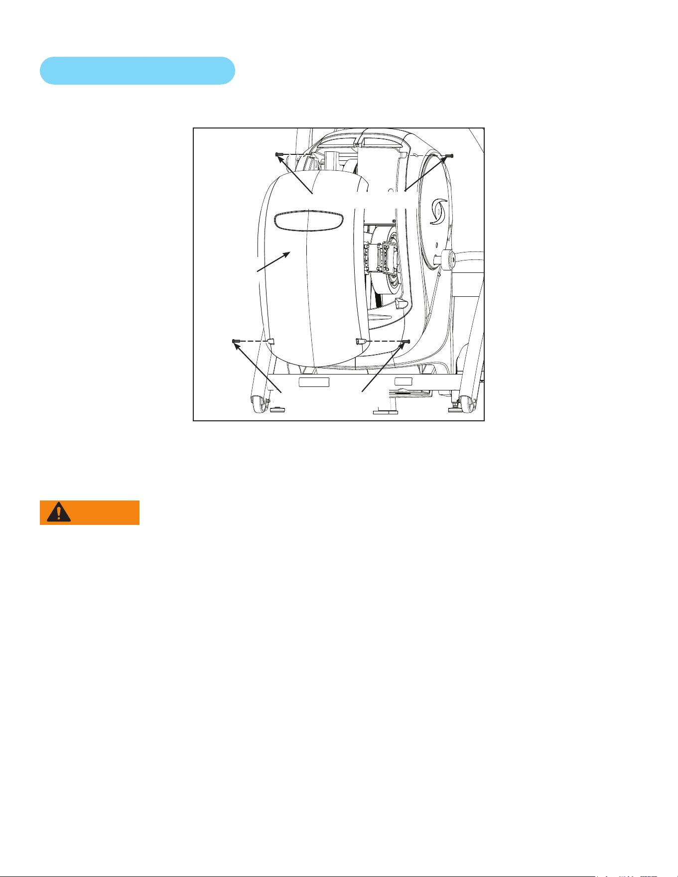
Cybex Arc Trainer 625A/625AT Owner’s Manual Cybex Arc Trainer 625A/625AT Owner’s Manual
74
Remove Access Cover
1. Remove the two lower screws securing the access cover using a Phillips screwdriver.
Lower Screws (2)
Access
Cover
Upper Screws (2)
2. Remove two upper screws securing the access cover using a Phillips screwdriver. Refer to the
above diagram.
3. Remove the access cover.
WARNING: Serious injury or death can occur. To avoid death or injury the following
precautions must be observed. Wait until ywheel cools before servicing. A
hot ywheel may burn user.
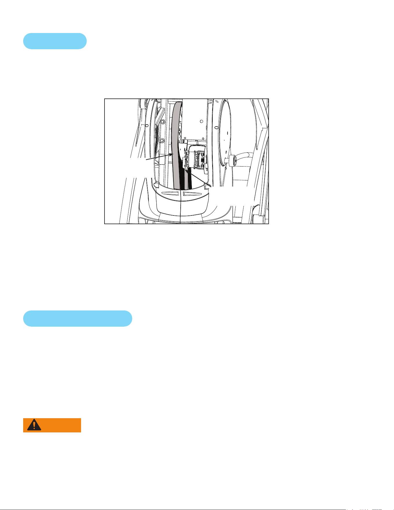
Cybex Arc Trainer 625A/625AT Owner’s Manual
75
Drive Belts
There are two drive belts that may become loose, worn or cracked.
Unless the belts have been removed and not replaced properly, it is unlikely the belts will come loose
or need to be re-tensioned.
Primary
Drive Belt
Secondary
Drive Belt
If a belt has cracks or appears worn, it must be replaced immediately by a qualied service
technician.
Primary Belt – The wider of the two belts. It has grooves that keep it aligned on the large upper
pulley.
Secondary Belt – The narrower of the two belts. It has grooves that keep it aligned on the ywheel’s
drive pulley.
Rechargeable Battery
The unit is designed with a 12 volt Lead-Acid rechargeable battery. The battery will recharge during
regular operation of unit or when the optional power adapter is plugged in.
The display will indicate dashes in the incline display if the battery fails to provide enough energy. The
unit will still function normally other than the disabling of the incline feature.
If the battery is completely discharged, the workout review will also be truncated if the user is not
striding during the time period. See Customer Service for contact information to replace the battery
or purchase the optional AC adapter kit.
WARNING: Serious injury or death can occur. To avoid death or injury the following
precautions must be observed. Battery replacement shall be performed by
qualied service technician.
Removebatteryanddisposeofsafelybeforeunitdisposal.

Cybex Arc Trainer 625A/625AT Owner’s Manual Cybex Arc Trainer 625A/625AT Owner’s Manual
76
Attach Access Cover
Do not over tighten screws.
1. Replace and tighten the two upper screws removed in step 2 Remove Access Cover using a
Phillips screwdriver.
2. Replace and tighten the two lower screws removed in step 1 Remove Access Cover using a
Phillips screwdriver.
3. Test unit for proper operation.
Recommended Service Schedule
All maintenance activities shall be performed by qualied personnel. Failure to do so could result in
serious injury.
This is the minimum recommended service.
Determine distance
1. Verify foot plates are completely stopped.
2. Grasp handrail and step carefully onto foot plates. Begin striding.
3. Press and the hold the SCAN/HOLD and DOWN keys for 3 seconds. A beep
signies the rst screen of the Statistics menu.
4. Menu navigation is done two ways:
Up/Down - The UP and DOWN keys allow you to scroll up and down in the statistics
menu.
The Statistics menu includes: Miles/Km, Hours, Starts, Battery and Error log.
5. The rst menu item is Miles/Km.
6. Record Distance.
7. Navigate to menu item Hours.
8. Record Hours.
9. Exit Statistics menu by pressing the Pause key.
First 500 Miles (800 KM)
Follow this procedure to ensure the belts are tensioned properly and in good condition.
1. Remove access cover. (See previous procedure Remove Access Cover)
2. Pull down and roll each belt to examine the condition. If a belt has cracks or appears worn, it
must be replaced immediately by a qualied service technician.

Cybex Arc Trainer 625A/625AT Owner’s Manual
77
3. Attach access cover. (See previous procedure Attach Access Cover)
Every 5000 Miles (8000 KM)
Check drive belts for tension and wear. (See procedure First 500 Miles)
Move unit and vacuum underneath. Lift the rear of unit and roll it back from its present
position. Vacuum underneath and return unit to normal position.
Clean inside unit.
1. Remove access cover. (See previous procedure Remove Access Cover)
2. Using a vacuum cleaner attachment or hand vacuum, clean the exposed components.
3. Remove dirt and debris from internal components.
4. Using a dry cloth, wipe all exposed areas.
5. Attach access cover. (See procedure Attach Access Cover)
Every 20,000 Miles (32000 KM)
Contact qualied service technician to check elevation assembly, replace any worn parts and
lubricate elevation bushings.

Cybex Arc Trainer 625A/625AT Owner’s Manual Cybex Arc Trainer 625A/625AT Owner’s Manual
78
Customer Service
Product Registration
To register product do the following:
1. Visit www.cybexintl.com.
2. Locate Product Registration in the Support section.
3. Fill out form completely.
4. Click the Submit button to register product.
Contacting Service
Hours of phone service are Monday through Friday from 8:30 a.m. to 6:00 p.m. Eastern Standard
Time.
For Cybex customers living in the USA, contact Cybex Customer Service at 888-462-9239.
For Cybex customers living outside the USA, contact Cybex Customer Service at 508-533-4300 or
fax 508-533-5183. email address [email protected]
Find information on the web at www.cybexintl.com.
To contact us online go to www.cybexintl.com. Select Support > Service. In the left navigation panel,
click Get Service - Service Request Form. Fill out form completely and click the Submit Query button.
Ordering Parts
To order parts online go to www.cybexintl.com. Select Support > Parts / Ordering. In the left
navigation panel, click Parts Diagrams - Current Products. Select from the drop down boxes.
To speak with a customer service representative, call 888-462-9239 (for customers living within the
USA) or 508-533-4300 (for customers outside the USA).
The following information located on the serial number decal will assist our Cybex representatives in
serving you.
• Unit Serial Number, Product Name and Model Number
• Part Description and Part Number if you have it. All parts can be found on the web at
• www.cybexintl.com
• Shipping Address
• Contact Name
• Include a description of the problem.
In addition to your shipping address and contact name, your account number is helpful but not
required. You may also fax orders to 508-533-5183.
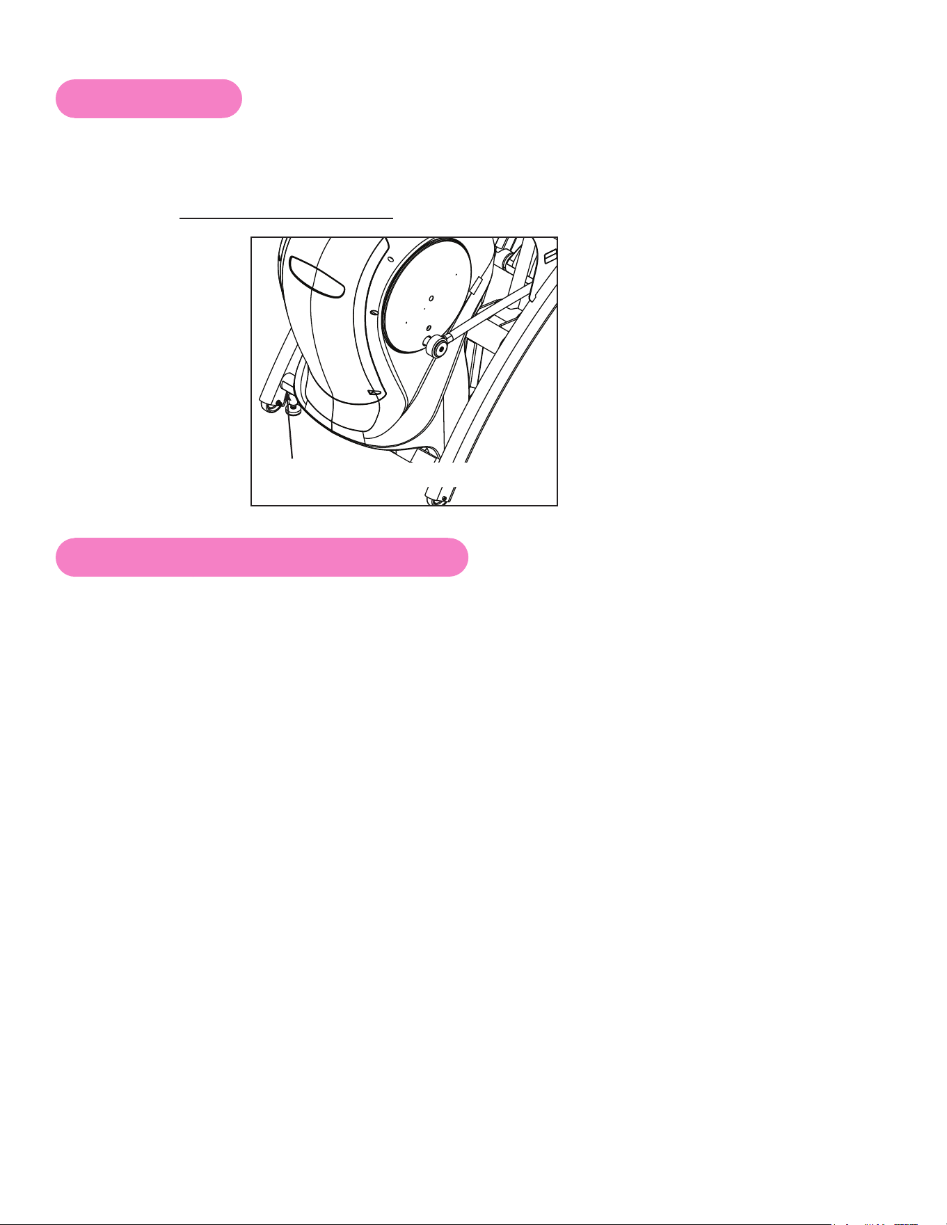
Cybex Arc Trainer 625A/625AT Owner’s Manual
79
Serial Number
The serial number can be found on the front of your unit. For your convenience, record your serial
number below so that you will have it ready if you call Cybex Customer Service.
Serial Number
Serial Number Location
Return Material Authorization (RMA)
The Return Material Authorization (RMA) system is used when returning material for placement,
repair or credit. The system assures that returned materials are properly handled and analyzed.
Follow the following procedures carefully.
Contact your authorized Cybex dealer on all warranty-related matters. Your local Cybex dealer will
request a RMA from Cybex, if applicable. Under no circumstances will defective parts or equipment
be accepted by Cybex without proper RMA and an Automated Return Service (ARS) label.
Please contact Cybex Customer Service for the return of any item that is defective.
Provide the technician with a detailed description of the problem you are having or the defect in the
item you wish to return. Provide the model and serial number of your Cybex equipment.
At Cybex’s discretion, the technician may request that you return the problem part(s) to Cybex for
evaluation and repair or replacement. The technician will assign you a RMA number and will send
you an ARS label. The ARS label and the RMA numbers must be clearly displayed on the outside
of the package that contains the item(s) to be returned. Include the description of the problem, the
serial number of the equipment and the name and address of the owner in the package along with the
part(s).
Merchandise returned without an RMA number on the outside of the package or shipments sent COD
will not be accepted by the Cybex receiving department.

Cybex Arc Trainer 625A/625AT Owner’s Manual Cybex Arc Trainer 625A/625AT Owner’s Manual
80
Damaged Parts
Materials damaged in shipment should not be returned for credit. Shipping damages are the
responsibility of the carrier (UPS, Federal Express, trucking companies, etc.)
Apparent Damage
Upon receipt of your shipment, check all items carefully. Any damage seen with a visual check must
be noted on the freight bill and signed by the carrier’s agent. Failure to do so will result in the carriers
refusal to honor your damage claim. The carrier will provide you with the required forms for ling such
claims.
Concealed Damage
Damage not seen with a visual check upon receipt of a shipment but notices later must be reported
to the carrier as soon as possible. Upon discovery of the damage, a written or phone request to
the carrier asking them to perform an inspection of the materials must be made within ten days of
the delivery date. Keep all shipping containers and packing materials as they will be needed in the
inspection process. The carrier will provide you with an inspection report and the necessary forms for
ling a concealed damage claim. Concealed damage claim is the carrier’s responsibility.
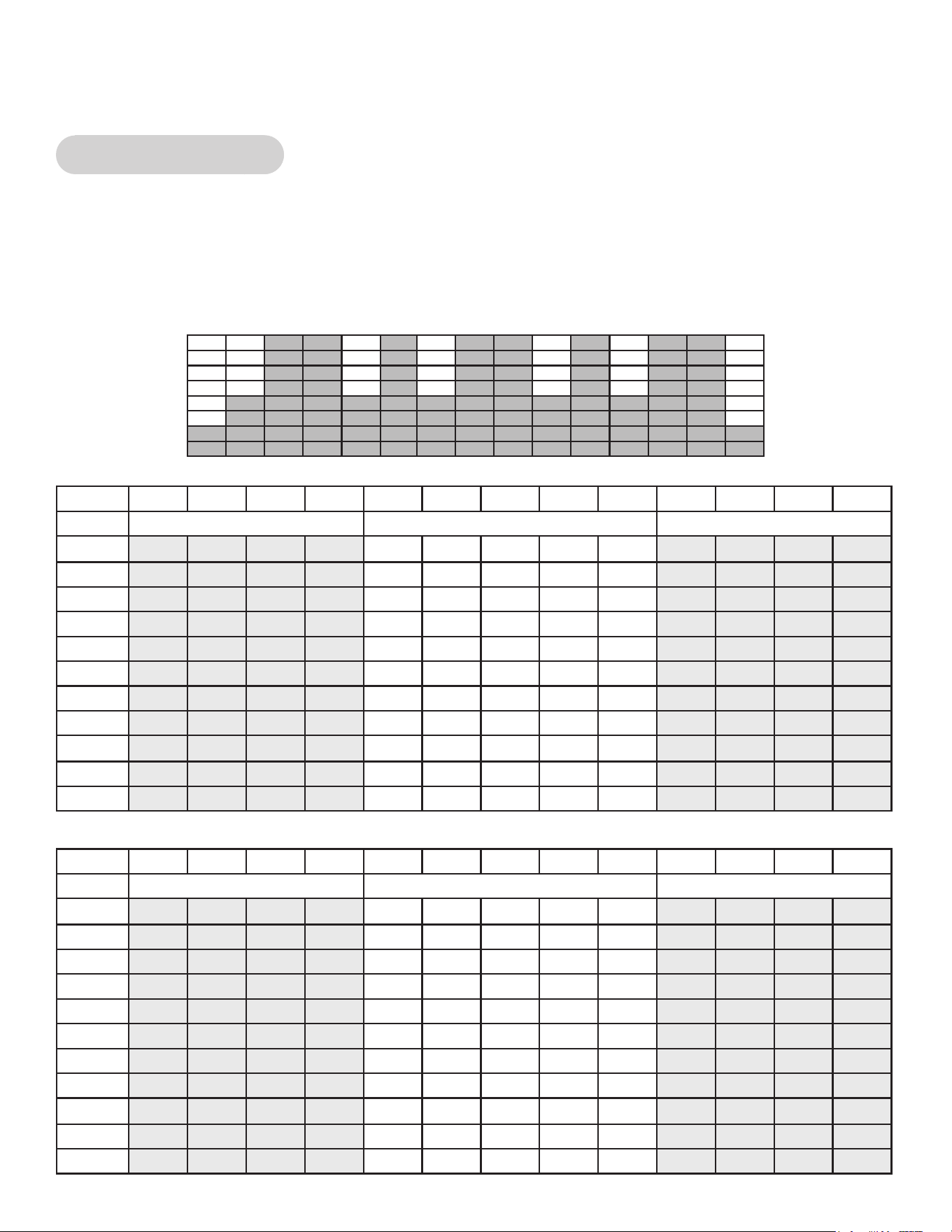
Cybex Arc Trainer 625A/625AT Owner’s Manual
81
Appendix - Program Overviews
P1: Weight Loss 1
The Weight Loss 1 program is a ve-minute core program designed for low to medium intensity
training that the user can sustain for an extended period of time. It builds from a low intensity baseline
to include short bursts of higher resistance while the elevation increases by fty percent for two-
minutes. The constant variety provides for periods of higher expenditure and training effect without
the introduction of undue fatigue allowing the user to perform for longer periods of time.
Resistance
Time :30 :30 :30 :30 1:00 1:00 1:00 1:00 1:00 :30 :30 :30 :30
Warm Up Program Segments Cool Down
1 2 3 4 1 2 3 4 5 1 2 3 4
10 5 10 15 20 25 45 45 25 45 20 15 10 5
9 5 10 15 20 25 40 40 25 40 20 15 10 5
8 5 10 15 20 25 35 35 25 35 20 15 10 5
7 5 5 10 15 25 40 40 25 40 15 10 5 5
6 5 5 10 15 25 35 35 25 35 15 10 5 5
5 5 5 10 15 25 30 30 25 30 15 10 5 5
4 5 5 5 10 15 25 25 15 25 10 5 10 8
3 5 5 5 10 15 20 20 15 20 10 5 10 8
2 5 5 5 5 5 15 15 5 15 5 4 3 3
1 5 5 5 5 5 10 10 5 10 5 4 3 3
Elevation
Time :30 :30 :30 :30 1:00 1:00 1:00 1:00 1:00 :30 :30 :30 :30
Warm Up Program Segments Cool Down
1 2 3 4 1 2 3 4 5 1 2 3 4
10 8 8 8 8 8 12 12 8 8 8 8 8 8
9 8 8 8 8 8 12 12 8 8 8 8 8 8
8 6 6 6 6 6 12 12 6 6 6 6 6 6
7 6 6 6 6 6 8 8 6 6 6 6 6 6
6 6 6 6 6 6 8 8 6 6 6 6 6 6
5 6 6 6 6 6 8 8 6 6 6 6 6 6
4 4 4 4 4 4 6 6 4 4 4 4 4 4
3 4 4 4 4 4 6 6 4 4 4 4 4 4
2 4 4 4 4 4 6 6 4 4 4 4 4 4
1 4 4 4 4 4 6 6 4 4 4 4 4 4
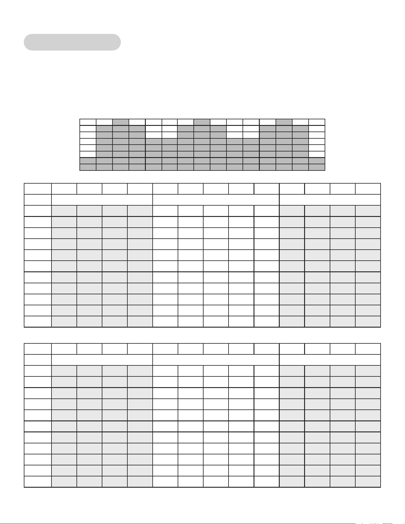
Cybex Arc Trainer 625A/625AT Owner’s Manual Cybex Arc Trainer 625A/625AT Owner’s Manual
82
P2: Weight Loss 2
The Weight Loss 2 program is a ve-minute core program that begins at a low intensity level and
incrementally increases both resistance and elevation until peaking after three-minutes and remains
at that level for one-minute before ramping back down to the initial level. The repetitive program is
designed to encourage a transition in training intensity to encourage the development of aerobic and
anaerobic energy systems.
Resistance
Time :30 :30 :30 :30 1:00 1:00 1:00 1:00 1:00 :30 :30 :30 :30
Warm Up Program Segments Cool Down
1 2 3 4 1 2 3 4 5 1 2 3 4
10 20 25 30 40 50 65 80 65 50 40 30 25 20
9 20 25 30 35 50 60 75 60 50 35 30 25 20
8 20 25 30 35 45 55 70 55 45 35 30 25 20
7 15 20 25 35 45 50 65 50 45 35 25 20 15
6 15 20 25 30 40 45 60 45 40 30 25 20 15
5 10 15 20 20 40 40 55 40 40 20 20 15 10
4 10 10 15 15 30 35 50 35 30 15 15 10 10
3 5 5 10 10 20 20 40 20 20 10 10 5 5
2 5 5 10 10 20 20 40 20 20 10 10 5 5
1 5 5 10 10 15 20 35 20 15 10 10 5 5
Elevation
Time :30 :30 :30 :30 1:00 1:00 1:00 1:00 1:00 :30 :30 :30 :30
Warm Up Program Segments Cool Down
1 2 3 4 1 2 3 4 5 1 2 3 4
10 6 8 10 10 12 16 20 16 12 10 10 8 6
9 6 8 10 10 11 15 19 15 11 10 10 8 6
8 6 8 8 8 10 14 18 14 10 8 8 8 6
7 6 8 8 8 9 13 17 13 9 8 8 6 6
6 6 8 8 8 8 12 16 12 8 8 8 6 6
5 6 8 8 8 7 11 14 11 7 8 8 6 6
4 6 8 8 8 6 9 12 9 6 8 8 6 6
3 6 8 8 8 5 8 10 8 5 8 8 6 6
2 6 8 8 8 4 6 8 6 4 8 8 6 6
1 6 8 8 8 3 5 6 5 3 8 8 6 6
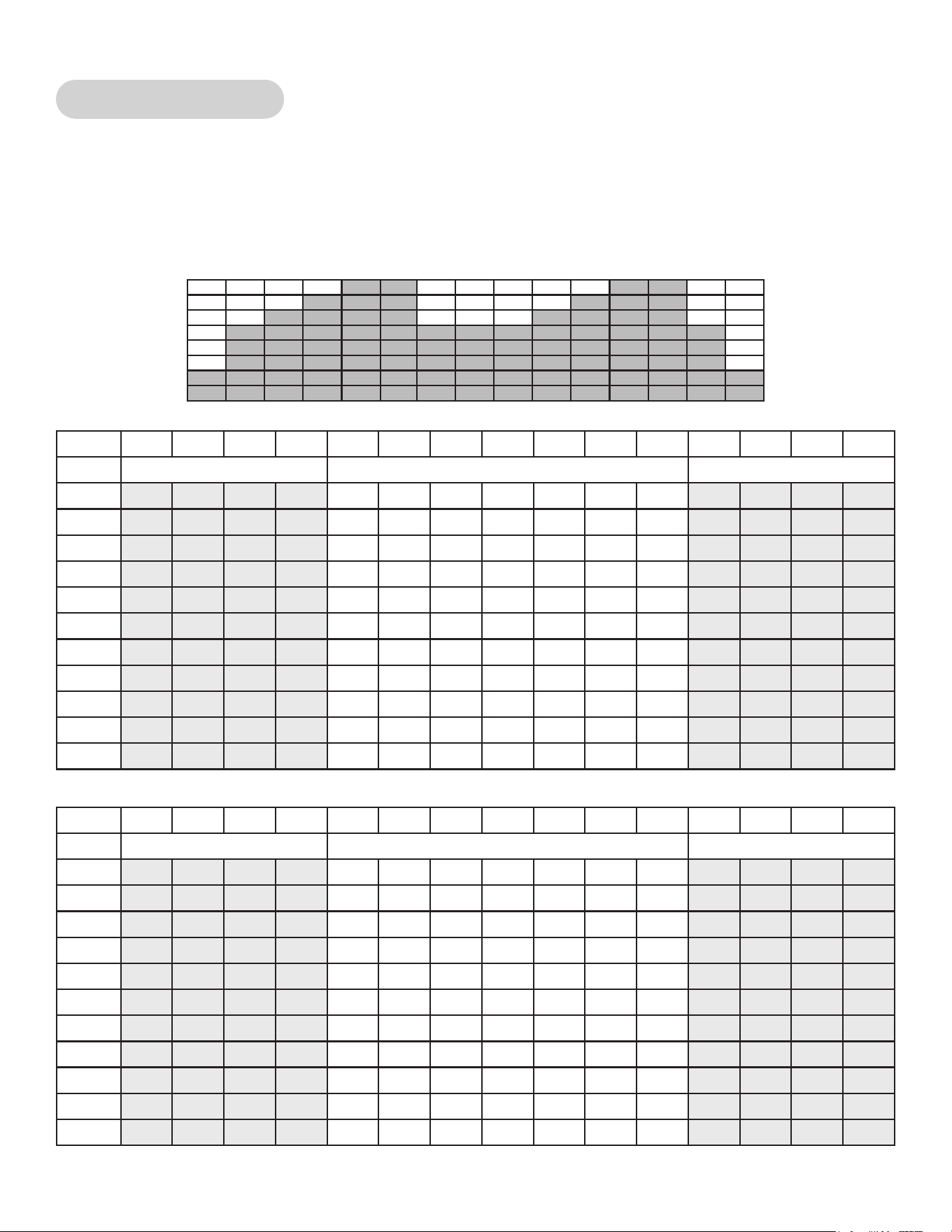
Cybex Arc Trainer 625A/625AT Owner’s Manual
83
P3: Weight Loss 3
The Weight Loss 3 program is a three-minute thirty-second core program designed to give the user
an intense workout. Users will experience moderate resistance and elevation at the beginning to
simulate the start of a climb and will crest at peak elevation gain and difcult resistance after two-
minutes. The resistance then returns to the preliminary level and the core program repeats itself for
the next hill.
Resistance
Time :30 :30 :30 :30 :30 :30 :30 :30 :30 :30 :30 :30 :30 :30 :30
Warm Up Program Segments Cool Down
1 2 3 4 1 2 3 4 5 6 7 1 2 3 4
10 20 30 40 50 50 55 65 75 80 50 50 50 40 30 20
9 20 30 40 45 45 50 60 70 75 45 45 45 40 30 20
8 20 30 35 40 40 45 55 65 75 40 40 40 35 30 20
7 15 25 35 35 35 45 50 60 70 35 35 35 35 25 15
6 15 25 30 35 35 40 50 55 65 35 35 35 30 25 15
5 15 25 30 30 30 35 45 50 60 30 30 30 30 25 15
4 10 20 25 30 25 30 40 50 55 25 25 30 25 20 10
3 10 20 25 25 20 30 40 45 50 20 20 25 25 20 10
2 10 15 20 25 20 25 35 40 45 20 20 25 20 15 10
1 10 10 15 15 20 20 30 35 40 20 20 15 15 10 10
Elevation
Time :30 :30 :30 :30 :30 :30 :30 :30 :30 :30 :30 :30 :30 :30 :30
Warm Up Program Segments Cool Down
1 2 3 4 1 2 3 4 5 6 7 1 2 3 4
10 6 8 10 12 16 16 18 20 20 14 14 12 10 8 6
9 6 6 8 10 14 16 16 18 20 13 13 10 8 6 6
8 6 6 8 8 14 14 16 18 18 12 12 8 8 6 6
7 6 6 8 8 12 14 14 16 18 11 11 8 8 6 6
6 6 6 6 8 12 12 14 16 16 10 10 8 6 6 6
5 6 6 6 6 10 12 12 14 16 9 9 6 6 6 6
4 4 4 4 6 10 10 12 14 14 8 8 6 4 4 4
3 4 4 4 6 8 10 10 12 14 7 7 6 4 4 4
2 4 4 4 4 8 8 10 12 12 6 6 4 4 4 4
1 4 4 4 4 6 8 8 10 12 5 5 4 4 4 4
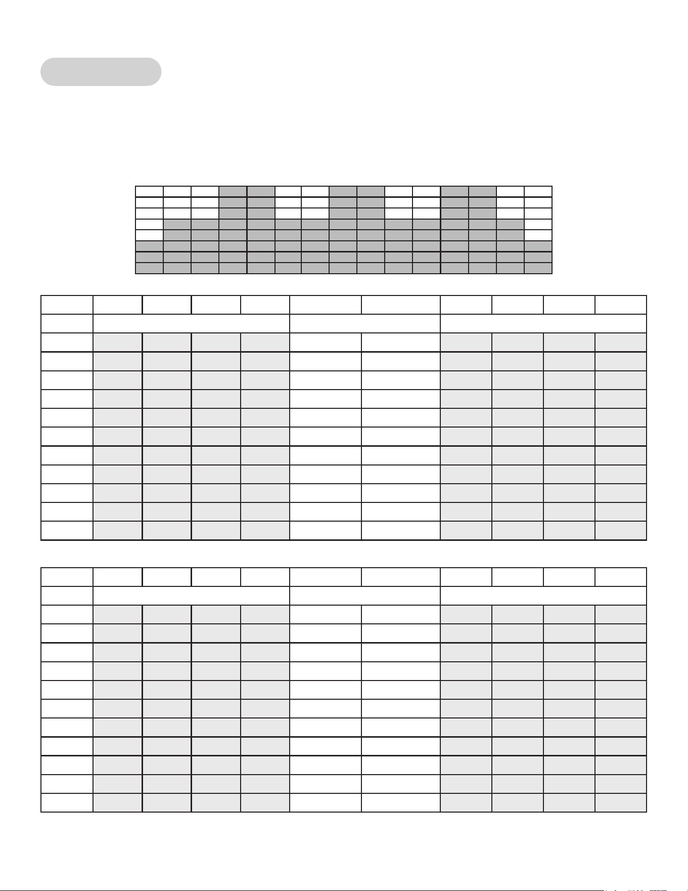
Cybex Arc Trainer 625A/625AT Owner’s Manual Cybex Arc Trainer 625A/625AT Owner’s Manual
84
P4: Cardio 1
The Cardio 1 program is a four-minute core program designed for medium intensity workouts. Users
will experience intervals of moderate resistance and elevation at the beginning to simulate the start of
a climb and greater resistance and steeper elevation after two-minutes. The resistance then returns to
the preliminary level and the core program repeats itself for the next interval.
Resistance
Time :30 :30 :30 :30 2:00 2:00 :30 :30 :30 :30
Warm Up Program Segments Cool Down
1 2 3 4 1 2 1 2 3 4
10 20 25 30 35 40 60 35 30 25 20
9 20 25 30 35 40 50 35 30 25 20
8 15 20 25 30 35 45 30 25 20 15
7 15 20 25 30 35 40 30 25 20 15
6 15 15 20 25 30 35 25 20 15 15
5 15 15 20 25 30 25 25 20 15 15
4 10 10 15 20 25 30 20 15 10 10
3 10 10 15 20 25 25 20 15 10 10
2 10 10 10 15 20 20 15 10 10 10
1 10 10 10 10 15 15 10 10 10 10
Elevation
Time :30 :30 :30 :30 2:00 2:00 :30 :30 :30 :30
Warm Up Program Segments Cool Down
1 2 3 4 1 2 1 2 3 4
10 6 8 10 12 12 20 12 10 8 6
9 6 6 8 10 10 20 10 8 6 6
8 6 6 8 10 10 18 10 8 6 6
7 6 6 6 8 8 18 8 6 6 6
6 6 6 6 8 8 16 8 6 6 6
5 6 6 6 6 6 16 6 6 6 6
4 6 6 6 6 6 14 6 6 6 6
3 4 4 6 6 6 14 6 6 4 4
2 4 4 6 6 6 12 6 6 4 4
1 4 4 6 6 6 12 6 6 4 4
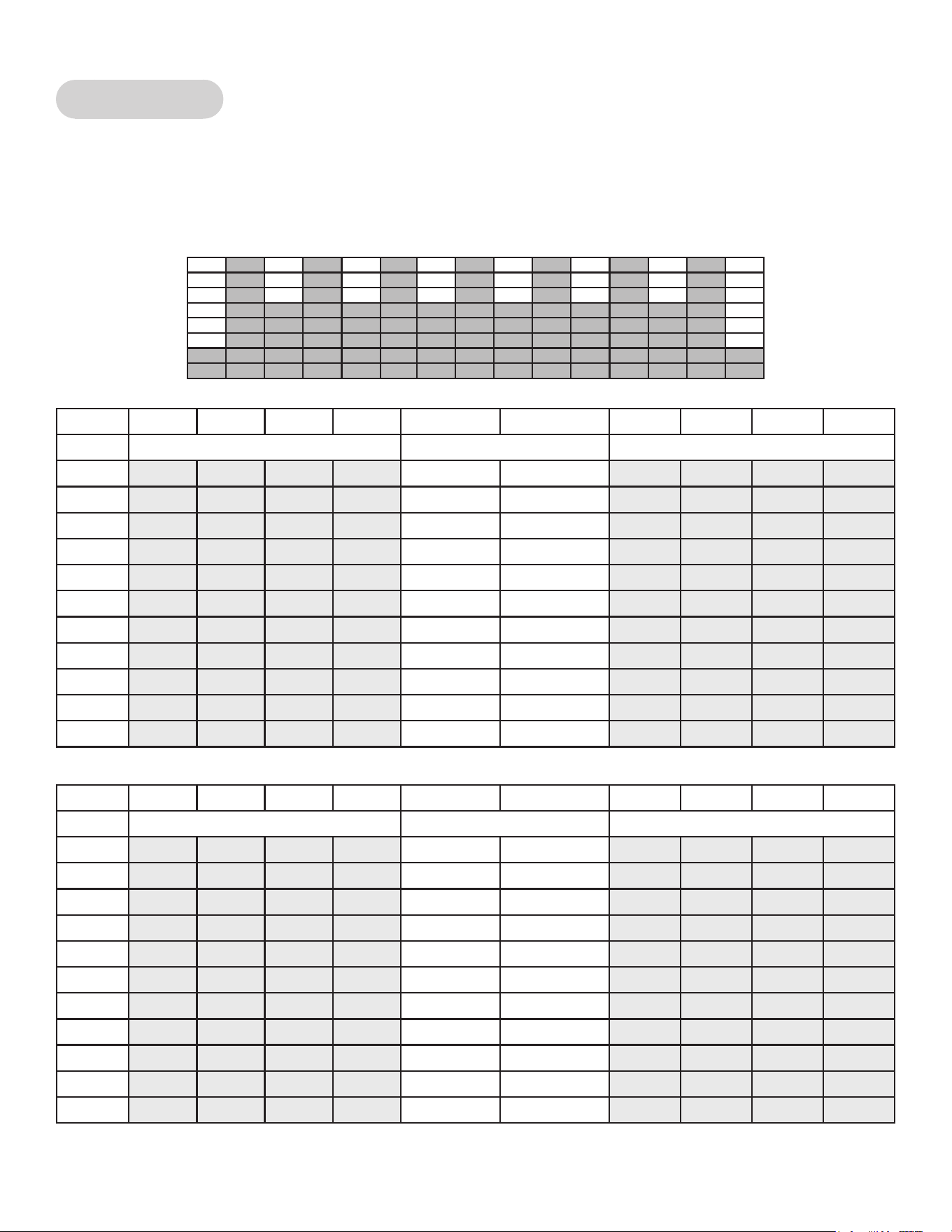
Cybex Arc Trainer 625A/625AT Owner’s Manual
85
P5: Cardio 2
The Cardio 2 program is a two-minute core program utilizing a 1:1 work to rest ratio. It is designed to
improve both aerobic and anaerobic capabilities as users will face a high level of resistance for one
minute followed by a one-minute recuperation period before performing the work interval again. The
elevation remains constant throughout the program.
Resistance
Time :30 :30 :30 :30 1:00 1:00 :30 :30 :30 :30
Warm Up Program Segments Cool Down
1 2 3 4 1 2 1 2 3 4
10 20 30 35 40 80 50 40 35 30 20
9 15 25 30 35 75 50 35 30 25 15
8 15 20 25 30 75 45 30 25 20 15
7 10 20 25 30 70 45 30 25 20 10
6 10 20 25 30 70 40 30 25 20 10
5 10 15 20 25 65 40 25 20 15 10
4 15 20 20 25 65 35 25 20 20 15
3 10 10 15 20 60 35 20 15 10 10
2 5 10 15 20 60 30 20 15 10 5
1 5 10 15 15 55 30 15 15 10 5
Elevation
Time :30 :30 :30 :30 1:00 1:00 :30 :30 :30 :30
Warm Up Program Segments Cool Down
1 2 3 4 1 2 1 2 3 4
10 8 8 12 16 20 20 16 12 8 8
9 8 8 12 16 20 20 16 12 8 8
8 8 8 12 12 16 16 12 12 8 8
7 8 8 12 12 16 16 12 12 8 8
6 8 8 12 12 16 16 12 12 8 8
5 8 8 8 12 12 12 12 8 8 8
4 8 8 8 8 12 12 8 8 8 8
3 8 8 8 8 12 12 8 8 8 8
2 8 8 8 8 8 8 8 8 8 8
1 8 8 8 8 8 8 8 8 8 8
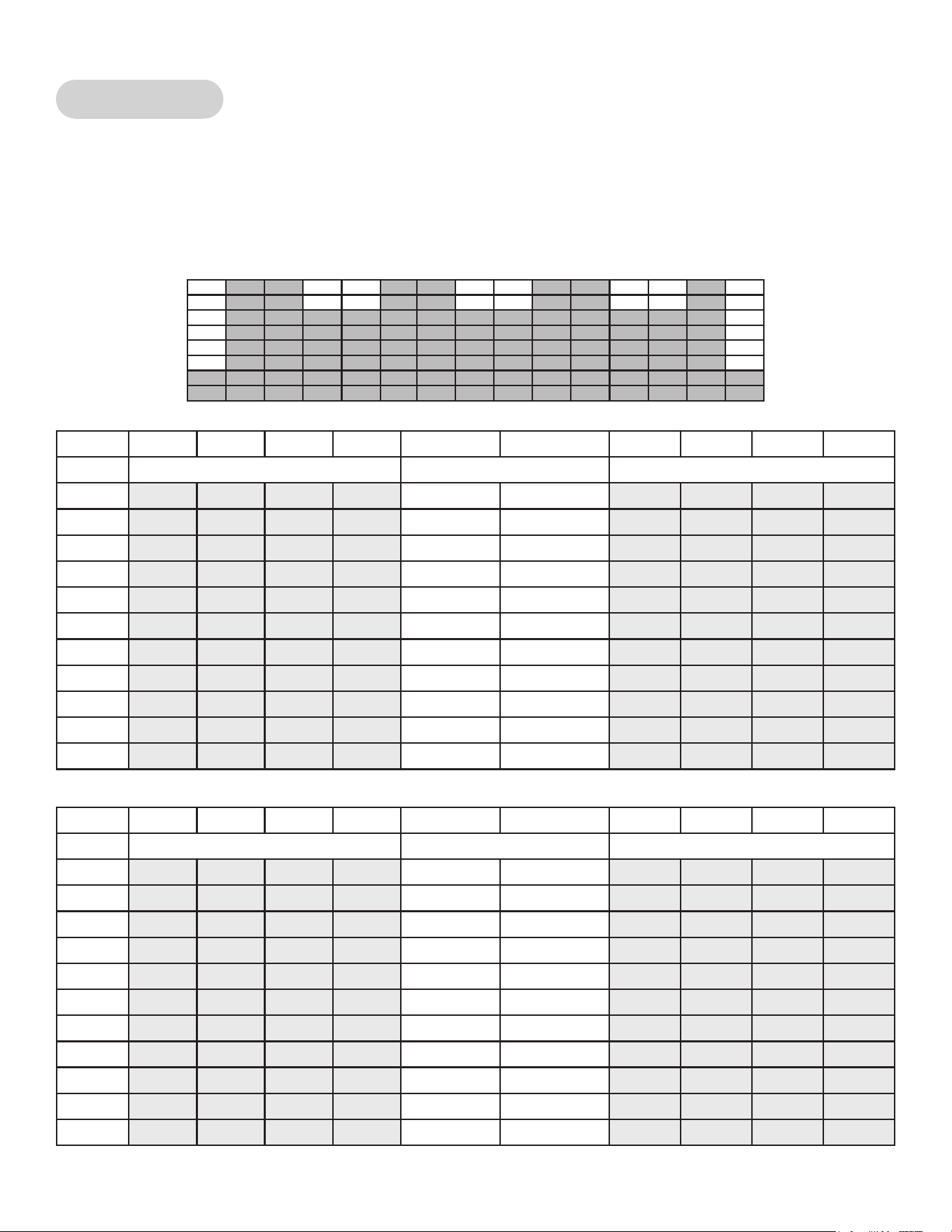
Cybex Arc Trainer 625A/625AT Owner’s Manual Cybex Arc Trainer 625A/625AT Owner’s Manual
86
P6: Cardio 3
The Cardio 3 program is designed to maintain a high total demand with two-minutes with high
resistance and low elevation and two minutes at medium resistance with higher elevation for a
total four-minute core program. The prolonged exertion period takes advantage of the long term
energy stores and total aerobic capability when associated with speeds that require a high sustained
cardiovascular demand.
Resistance
Time :30 :30 :30 :30 2:00 2:00 :30 :30 :30 :30
Warm Up Program Segments Cool Down
1 2 3 4 1 2 1 2 3 4
10 30 35 45 55 80 60 55 45 35 30
9 25 35 45 55 75 55 55 45 35 25
8 25 30 40 45 70 50 45 40 30 25
7 20 25 35 40 65 45 40 35 25 20
6 15 20 30 35 60 40 35 30 20 15
5 15 20 25 30 55 35 30 25 20 15
4 10 15 20 25 50 30 25 20 15 10
3 5 10 15 20 45 30 20 15 10 5
2 0 5 10 15 40 25 15 10 5 0
1 0 0 5 10 35 20 10 5 0 0
Elevation
Time :30 :30 :30 :30 2:00 2:00 :30 :30 :30 :30
Warm Up Program Segments Cool Down
1 2 3 4 1 2 1 2 3 4
10 6 8 10 12 10 16 12 10 8 6
9 6 6 8 10 10 16 10 8 6 6
8 6 6 8 8 10 14 8 8 6 6
7 6 6 8 8 8 14 8 8 6 6
6 6 6 6 8 8 12 8 6 6 6
5 6 6 6 6 8 12 6 6 6 6
4 4 4 4 6 6 10 6 4 4 4
3 4 4 4 6 6 10 6 4 4 4
2 4 4 4 4 4 8 4 4 4 4
1 4 4 4 4 4 8 4 4 4 4
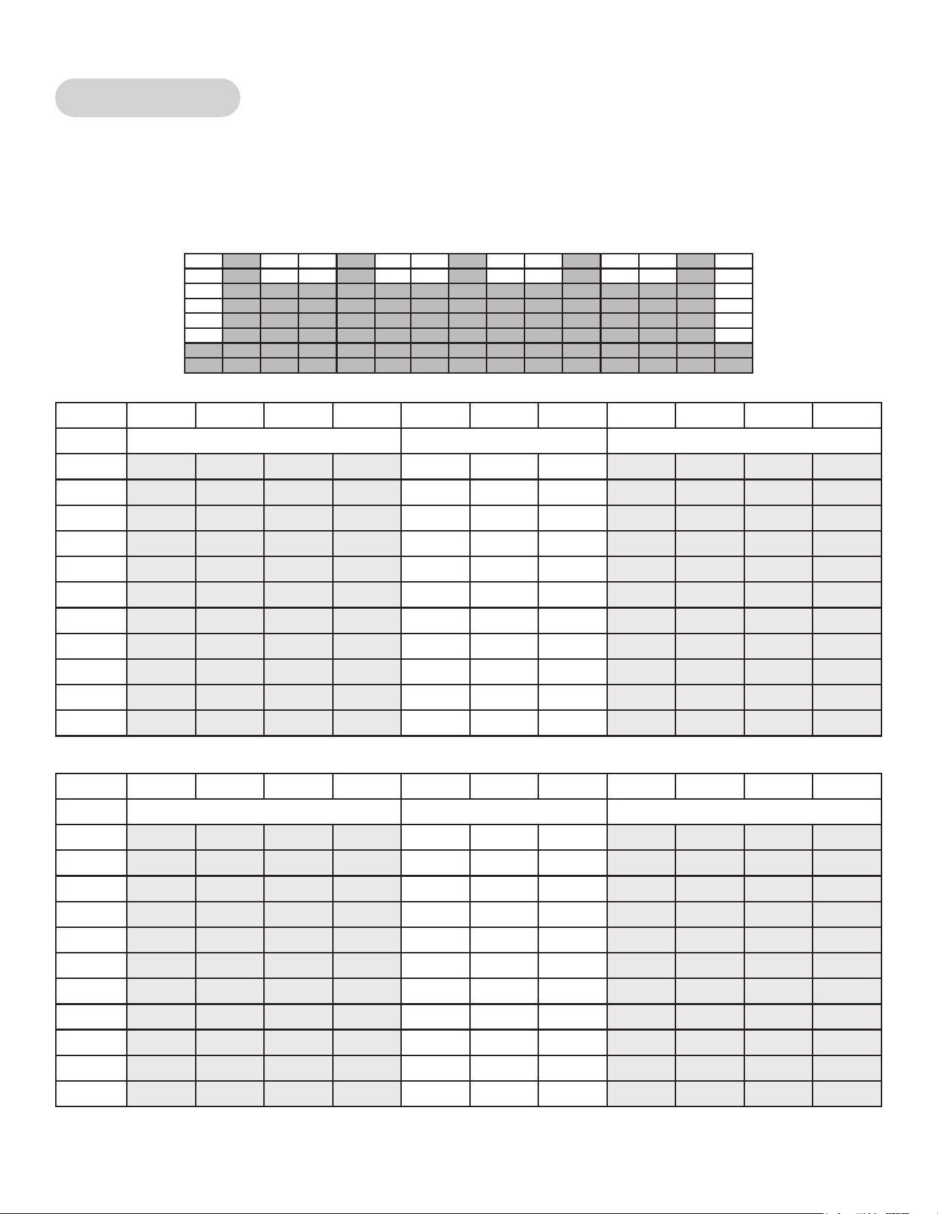
Cybex Arc Trainer 625A/625AT Owner’s Manual
87
P7: Strength 1
The Strength 1 program uses a 1:2 work to rest ratio. It is designed for high resistance training with
longer rest periods than the 1:1 program. Users will face a high level of resistance for thirty-seconds
followed by a one minute recuperation period before performing the interval again. The elevation
remains constant throughout the program.
Resistance
Time :30 :30 :30 :30 :30 :30 :30 :30 :30 :30 :30
Warm Up Program Segments Cool Down
1 2 3 4 1 2 3 1 2 3 4
10 35 45 55 65 70 45 45 40 35 30 20
9 35 40 50 60 65 40 40 35 30 25 15
8 30 40 50 55 60 35 35 30 25 20 15
7 30 35 45 50 55 30 30 30 25 20 10
6 25 35 40 45 50 30 30 30 25 20 10
5 25 30 35 40 45 25 25 25 20 15 10
4 20 25 30 35 40 25 25 25 20 15 10
3 20 25 30 30 35 20 20 20 15 10 10
2 15 20 25 30 30 20 20 20 15 10 5
1 10 15 20 20 25 15 15 15 15 10 5
Elevation
Time :30 :30 :30 :30 :30 :30 :30 :30 :30 :30 :30
Warm Up Program Segments Cool Down
1 2 3 4 1 2 3 1 2 3 4
10 8 8 12 16 20 20 20 16 12 8 4
9 8 8 12 16 20 20 20 16 12 8 4
8 8 8 12 12 16 16 16 12 12 8 4
7 8 8 12 12 16 16 16 12 12 8 4
6 8 8 12 12 16 16 16 12 12 8 4
5 8 8 8 12 12 12 12 12 8 8 4
4 8 8 8 8 12 12 12 8 8 8 4
3 8 8 8 8 12 12 12 8 8 8 4
2 8 8 8 8 8 8 8 8 8 8 4
1 8 8 8 8 8 8 8 8 8 8 4
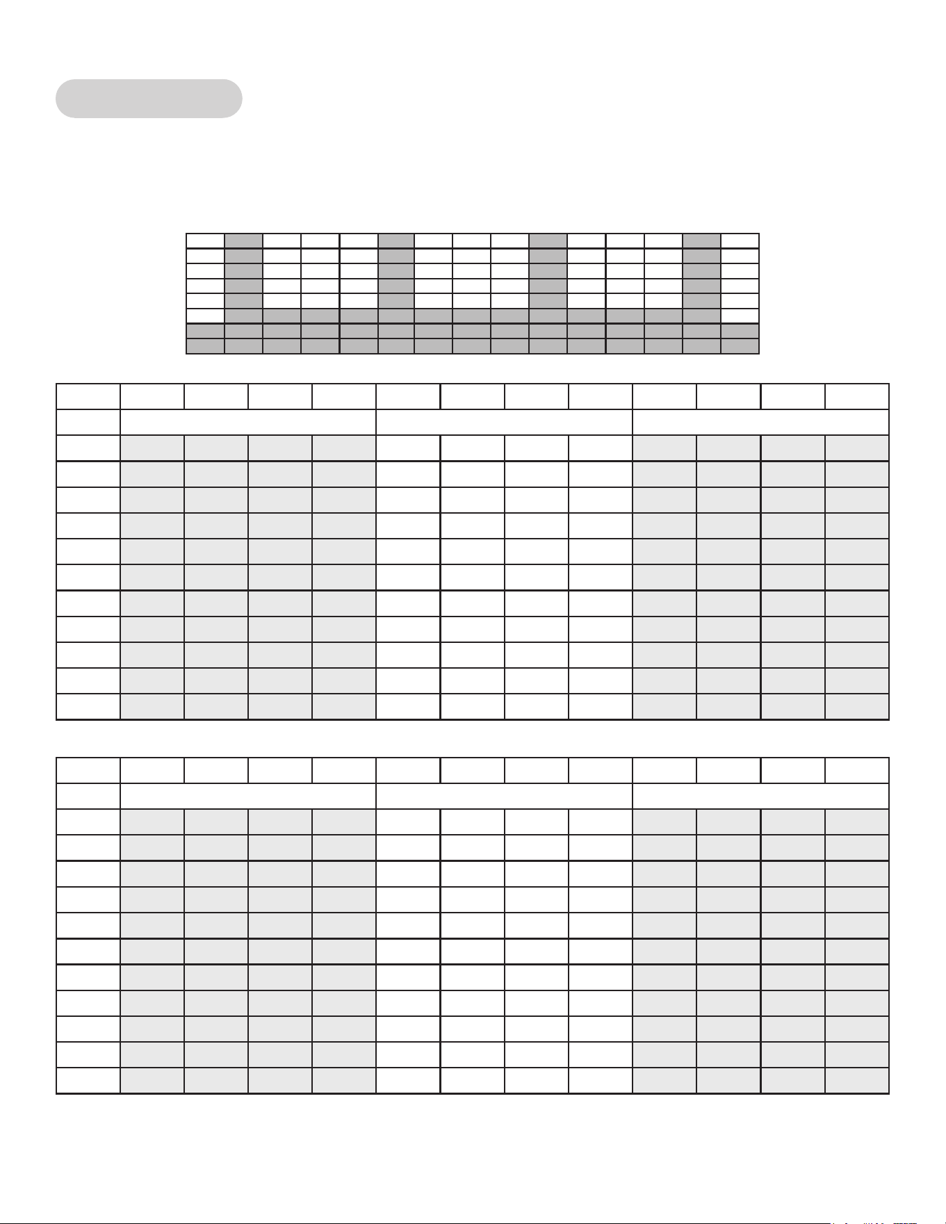
Cybex Arc Trainer 625A/625AT Owner’s Manual Cybex Arc Trainer 625A/625AT Owner’s Manual
88
P8: Strength 2
The Strength 2 program is designed with the specic goal of raising the users’ lactic acid threshold.
The program uses a 1:3 work to rest ratio with fteen-second intervals for maximum power
development and forty-ve second rest periods for recuperation.
Resistance
Time :30 :30 :30 :30 :15 :15 :15 :15 :30 :30 :30 :30
Warm Up Program Segments Cool Down
1 2 3 4 1 2 3 4 1 2 3 4
10 25 30 40 45 100 35 35 35 30 25 20 15
9 25 30 35 40 95 35 35 35 30 25 20 15
8 25 30 35 40 90 35 35 35 30 25 20 15
7 25 30 35 40 85 30 30 30 25 20 20 15
6 20 25 30 35 80 30 30 30 25 20 20 15
5 20 25 30 35 75 30 30 30 25 20 15 10
4 20 5 30 35 70 25 25 25 20 20 0 0
3 20 20 25 30 65 25 25 25 20 20 0 0
2 15 20 25 30 60 20 20 20 15 0 10 5
1 15 15 20 25 55 20 20 20 15 0 10 5
Elevation
Time :30 :30 :30 :30 :15 :15 :15 :15 :30 :30 :30 :30
Warm Up Program Segments Cool Down
1 2 3 4 1 2 3 4 1 2 3 4
10 10 12 16 18 20 20 20 20 18 16 12 10
9 10 12 16 18 20 20 20 20 18 16 12 10
8 10 12 14 16 18 18 18 18 16 14 12 10
7 10 12 14 16 18 18 18 18 16 14 12 10
6 10 12 14 16 18 18 18 18 16 14 12 10
5 8 10 12 14 16 16 16 16 14 12 10 8
4 8 10 12 14 16 16 16 16 14 12 10 8
3 8 10 12 14 16 16 16 16 14 12 10 8
2 6 8 10 12 14 14 14 14 12 10 8 6
1 6 8 10 12 14 14 14 14 12 10 8 6

Cybex Arc Trainer 625A/625AT Owner’s Manual
89
P9: Heartrate Control
The Heartrate Control (HRC) program will attempt to bring the user to their target heartrate in 3-5
minutes, then keep them there for the duration of the body of the program. A Cool Down is built in to
the end of the program. HRC is run in Constant Power and thus denes watts.
The user selects a target heartrate, which defaults to 75% of max (max is 220-age). Limits should be
set to not allow a Target HR (THR) less than 60% of max or more than 95% of max.
The protocol starts in Stage II, with the entry point based on Target HR.
• 80 – 120 BPM = Step 6
• 121-127 BPM = Step 8
• 128-134 BPM = Step 10
• 135-up BPM = Step 12
A running pulse-to-pulse BPM value is continuously measured.
Every 15 seconds the user’s pulse rate is sampled and a prediction function is evaluated (decision.)
This is subtracted from the target heartrate to form an error value which is scaled and added to the
current load value. There is a maximum rate of change of 15 steps per decision.
The workload equates to the speed and incline load of the 750T Treadmill HRC Program. A chart of
Step and Watts has been created. It has four dened stages:
• Stage 1 ramps the load from Step 1 to Step 5.
• Stage 2 ramps the load from Step 6 through Step 18.
• Stage 3 ramps the load from Step 19 through Step 39.
• Stage 4 ramps the load from Step 40 through Step 100.
The user has full control over incline throughout the program, with incline having no bearing on
the program at all. The user has limited control over the load in that the user’s selections are not
permanent. At the next decision, a new load can be chosen by the software as described above to
override any user modications.
If the user presses the LEVEL key, they can modify their Target Heartrate real-time. Utilize the Target
Heartrate Setup selection screen and exit back to the program in progress, making the change to
their target heartrate real-time.
Lost Signal
If a signal is lost for two consecutive decisions (roughly 30 seconds), the display will beep four times,
show ‘HR SIGNAL LOST’, show dashes in the BPM window and show the heart solid white. During
this HR signal lost period, the load will remain steady.
If after two further decisions (roughly an additional 30 seconds) the heartrate signal has not been
reestablished, continue to show ‘HR SIGNAL LOST’ on the Text area. The program will reduce the
workload by 10 steps per minute until minimum workload or Step 1. After one minute at minimum
workload, go to Exiting Active Mode.

Cybex Arc Trainer 625A/625AT Owner’s Manual Cybex Arc Trainer 625A/625AT Owner’s Manual
90
Cool Down
By default, Cool Down occurs at session time minus two minutes or if the user presses the Cool
Down button. Cool Down goes to 75% of existing step, then drops by 1 step every 15 seconds for the
remainder of Cool Down.
Stage 1 Stage 2 Stage 3 Stage 4
Step Watts Step Watts Step Watts Step Watts
1 25 6 50 19 115 40 220
2 30 7 55 20 120 41 225
3 35 8 60 21 125 42 230
4 40 9 65 22 130 43 235
5 45 10 70 23 135 44 240
11 75 24 140 45 245
12 80 25 145 46 250
13 85 26 150 47 255
14 90 27 155 48 260
15 95 28 160 49 265
16 100 29 165 50 270
17 105 30 170 51 275
18 110 31 175 52 280
32 180 53 285
33 185 54 290
34 190 55 295
35 195 56 300
36 200 57 305
37 205 58 310
38 210 59 315
39 215 60 320
61 325
62 330
63 335
64 340
65 345
66 350
67 355
68 360
69 365
70 370
71 375
72 380
73 385
74 390

Cybex Arc Trainer 625A/625AT Owner’s Manual
91
Stage 1 Stage 2 Stage 3 Stage 4
Step Watts Step Watts Step Watts Step Watts
75 395
76 400
77 405
78 410
79 415
80 420
81 425
82 430
83 435
84 440
85 445
86 450
87 455
88 460
89 465
90 470
91 475
92 480
93 485
94 490
95 495
96 500
97 505
98 510
99 515
100 520

Cybex Arc Trainer 625A/625AT Owner’s Manual Cybex Arc Trainer 625A/625AT Owner’s Manual
92

Cybex Arc Trainer 625A/625AT Owner’s Manual
93

10 Trotter Drive Medway, MA 02053 • 508-533-4300 • FAX 508-533-5183
www.cybexintl.com • [email protected]