Cybex 770A/770AT Arc Trainer
®
Owner’s Manual
Cardiovascular Systems
Part Number 5770-4 D
www.cybexintl.com

2
Cybex Owner’s Manual
Cybex® and the Cybex logo are registered trademarks of Cybex International, Inc. Polar
®
is a registered trademark of Polar Electro Inc. iPOD
®
is
registered trademark of Apple.
DISCLAIMER: Cybex International, Inc., makes no representations or warranties regarding the contents of this manual. We reserve the right to revise
this document at any time or to make changes to the product described within it without notice or obligation to notify any person of such revisions or
changes.
© Copyright 2014, Cybex International, Inc. All rights reserved. Printed in the United States of America.
10 Trotter Drive Medway, MA 02053 • 508-533-4300 • FAX 508-533-5183 • www.cybexintl.com • 5770-4 D • August 2014
FCC Compliance Information ............. 3
Safety
Ground and Voltage Information........... 4
Important Safety Instructions ............. 5
Warnings and Cautions ................. 8
Label Placement....................... 9
Assembly
Specications - 770A .................. 10
Specications - 770AT ................. 11
Environment and Storage............... 12
Choosing and Preparing Site . . . . . . . . . . . . 12
Electrical Power Requirements .......... 12
770A Assembly Procedure .............. 13
Tools Required...................... 13
770AT Assembly Procedure ............. 26
Tools Required...................... 26
Setup .............................. 43
A/V Conguration and FM Radio Presets... 45
E3 View Monitor Controls............... 51
E3 View Monitor Setup................. 52
Testing Operation ..................... 60
Operation
Intended Use ........................ 61
Terms Used ......................... 61
User Control Symbols Used ............. 62
CardioTouch Symbols Used ............. 63
CardioTouch Symbols Used (continued) ... 64
Console Display . . . . . . . . . . . . . . . . . . . . . . 65
Muscle Map and Incline Meter . . . . . . . . . . . 66
CardioTouch Screen and User Controls.... 67
Mount and Dismount .................. 68
Emergency Dismount .................. 68
Range of Motion ...................... 69
Quick Operation Guide................. 70
Detailed Operation Guide............... 70
Workout Selection .................... 72
Data Readouts - LED display ............ 73
E3 View Monitor Screen Options ......... 74
Heart Rate Indicator ................... 74
Fan Control.......................... 75
iPod Functions ....................... 75
Maintenance
Warnings ........................... 76
Cleaning Unit ........................ 77
Preventive Maintenance Activities ........ 77
Remove Access Cover ................. 78
Drive Belts .......................... 79
Rechargeable Battery.................. 79
Attach Access Cover .................. 80
E3 View Monitor ...................... 80
Recommended Service Schedule ........ 81
Statistics ............................ 82
Customer Service
Product Registration................... 83
Contacting Service .................... 83
Ordering Parts ....................... 83
Serial Number........................ 84
Return Material Authorization (RMA) ...... 84
Damaged Parts....................... 85
Appendix - Workout Overviews
Weight Loss - Hill Climb ................ 86
Weight Loss - Speed Bump ............. 87
Strength - High Low ................... 88
Strength - Bursts...................... 89
Strength - Interval..................... 90
Fitness (Mens) , Shaping (Womens)
- Total Leg ......................... 91
Fitness (Mens) - Target: Hip,
Shaping (Womens) - Glute Camp ....... 92
Cardio - Wave........................ 93
Cardio - Interval ...................... 94
Cardio - Heart Rate Control ............. 95
Power - Constant Power................ 95
Power - Adaptive Power ................ 95
Table of Contents

3
Cybex Owner’s Manual
FCC Compliance Information
Changes or modications to this unit not expressly approved by the party responsible for
compliance could void the user’s authority to operate the equipment!
This equipment has been tested and found to comply with the limits for a Class B digital device,
pursuant to part 15 of the FCC Rules. These limits are designed to provide reasonable protection
against harmful interference in a residential installation. This equipment generates, uses and can
radiate radio frequency energy and, if not installed and used in accordance with the instructions, may
cause harmful interference to radio communications. However, there is no guarantee that interference
will not occur in a particular installation. If this equipment does cause harmful interference to radio
or television reception, which can be determined by turning the equipment off and on, the user is
encouraged to try to correct the interference by one or more of the following measures:
• Reorient or relocate the receiving antenna.
• Increase the separation between the equipment and receiver.
• Connect the equipment into an outlet on a circuit different from that to which the receiver is
connected.
• Consult the dealer or an experienced radio/TV technician for help.
Cybex Owner’s Manual
4
Safety
Read all instructions and warnings before using.
Ground and Voltage Information
DANGER: Death or serious injury can occur. To avoid death or serious injury the
following precautions must be observed. Equipment must be properly
grounded. Check with a qualied electrician or service provider to verify the
unit is properly grounded. Improper connection of equipment grounding can
result in electric shock.
For E3 View Monitor or Optional Power Supply
• Unit must be grounded. This unit is equipped with an optional equipment-grounding conductor cord
and a grounding plug.
• Do not use a ground plug adapter to adapt the power cord to a non-grounded outlet.
• Plug must be plugged into an appropriate outlet that is properly installed and grounded in
accordance with all local codes and ordinances.
• If unit malfunctions, grounding provides path of least resistance for electric current to reduce risk of
electric shock.
Cybexisnotresponsibleforinjuriesordamagesasaresultofcordorplugmodication.
• Verify voltage requirements of unit match local voltage requirements.
• Verify unit outlet is the same conguration as the plug.
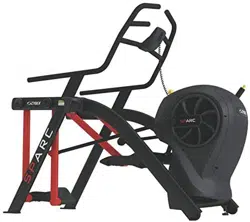
Power
Adapter
Power Cord
UseCybexsuppliedpoweradapterandpowercordsonly.
Connector
Varies by
Country

Cybex Owner’s Manual
4 5
Important Safety Instructions
(Save These Instructions)
DANGER: Death or serious injury can occur. To avoid death or injury the following
procedure must be followed. Always unplug this unit from the electrical outlet
before cleaning. Unplugging equipment reduces risk for shock.
User Safety Precautions
• KEEP ALL CHILDREN 12 AND UNDER AWAY! Teenagers or disabled must be supervised.
• Obtain a medical exam before beginning any exercise program.
• Stop exercising if feeling faint, dizzy, or experiencing pain and consult your physician.
• Obtain instruction before using.
• Read and understand all warnings posted on the unit before using.
• Use the handrails for support and to maintain balance.
• Wait until foot plates come to a complete stop before dismounting.
• Keep foot plate surface clean and dry.
• DO NOT wear loose or dangling clothing while using.
• Keep all body parts and other items free and clear of moving parts.
• DO NOT use unit if user exceeds 400 lbs. (180 kg). This is the rated maximum user weight.
• Report any malfunctions, damage or repairs to the facility.
• Replace any warning labels if damaged, worn or illegible.
Facility Safety Precautions
It is the sole responsibility of the user/owner or facility operator to ensure that regular maintenance is
performed.
• Enforce all user and safety precautions.
• Read and understand the Owner’s Manual completely before assembling, servicing or using unit.
• Verify all users are properly trained on using the equipment.
• Do not use unit outdoors.
• Verify that each unit is setup, leveled and operated on a solid level surface. Do not install equipment
on an uneven surface.
• Verify there is enough room for safe access and operation of unit.
• Use Cybex AC power adapters only.
• Do not use the optional power adapter in damp or wet locations.
• Do not use the unit if: (1) the unit is plugged into an optional power adapter that has a damaged
cord; (2) the unit is not working properly or (3) if the unit has been dropped or damaged. Seek
service from a qualied technician.
• EQUIPMENT is not suitable for use in the presence of aerosol (spray), FLAMMABLE
ANAESTHETIC MIXTURE WITH AIR or WITH OXYGEN or NITROUS OXIDE.
• Perform regular maintenance checks on unit. Performance level can be maintained only if
examined regularly. Pay close attention to all areas most susceptible to wear, including (but not
limited to) cables, pulleys, belts and grips.
• Replace any warning labels if damaged, worn, or illegible.
• Immediately replace worn or damaged components. If unable to immediately replace worn or
damaged components, then remove unit from service until repair is made.

Cybex Owner’s Manual
6
• Do not attempt electrical or mechanical repairs. Seek qualied repair personnel when servicing. If
you live in the USA, contact Cybex Customer Service at 888-462-9239. If you live outside the USA,
contact Cybex Customer Service at 508-533-4300.
• Use only Cybex supplied components to maintain/repair unit.
• Keep a repair log of all maintenance activities.
• Disconnect the optional power adapter before servicing unit.
• Do not use attachments unless recommended for the unit by Cybex.
• The unit may generate electromagnetic or other forms of interference, or it may be affected by
interference from other equipment nearby. If this is suspected, take precautions by separating the
equipment or otherwise shielding it to avoid such interference.
Unit with E3 View Monitor option
WARNING: Serious injury or death can occur. To avoid injury or death the following
procedure must be followed. Monitor must be connected to a mains socket
outlet with a protective earthing connection. Failure to connect monitor
correctly could result in electrical shock. Do not alter the mains plug or
coupler. Both are used as a disconnection device. It must remain operable or
the safety of the equipment is at risk. Do not expose this monitor to rain or
moisture. Exposing monitor to moisture could result in electrical shock.
• The product is supplied with electricity. Rain or moisture increases the risk of electric shock.
• Do not interfere with the enclosure. The lightning ash with arrowhead symbol within an equilateral
triangle, is intended to alert the user to the presence of non-insulated “dangerous voltage“ within
the product’s enclosure that may be of sufcient magnitude to constitute a risk of electric shock to
persons.
• The exclamation point within an equilateral triangle is intended to alert the user to the presence of
important operating and maintenance (servicing) instructions in the literature accompanying the
product.
• Ensure that used batteries are disposed of safely. Do not dispose of electrical products in the
general waste. When your monitor has reached the end of its life, contact your local city council
regarding available recycling or disposal options.
• Electricity is used to perform many useful functions, but it can also cause personal injuries and
property damage if improperly handled. This product has been engineered and manufactured with
safety being the highest priority. However, improper use can result in personal injury and/or property
damage.
• Read and keep these instructions.
• Heed all warnings and follow all instructions.
• Do not use this monitor near water.
• Dust off the panel with a soft dry cloth as needed. The screen can be cleaned with computer screen
wipes or other non abrasive, moist, disposable wipes.
• Do not block any ventilation openings. Install in accordance with the manufacturer’s instructions.
• Do not install near any heat sources such as radiators, heat registers, stoves, or other apparatus
(including ampliers) that produce heat.
• No naked ame sources, such as lighted candles, should be placed on the monitor.
• Do not expose batteries to excessive heat sources.

Cybex Owner’s Manual
6 7
• Do not defeat the safety purpose of the polarized or grounding-type plug. A polarized plug has two
blades with one wider than the other. A grounding type plug has two blades and a third grounding
prong. The wide blade or the third prong is provided for safety. If the provided plug does not t into
outlet, consult an electrician for replacement of the obsolete outlet.
• Protect the power cord from being walked on or pinched particularly at plugs, convenience
receptacles, and the point where they exit from the monitor.
• Only use attachments/accessories specied by the manufacturer.
• Unplug this monitor during lightning storms or when unused for long periods of time.
• Refer all servicing to qualied service personnel. Servicing is required when the monitor has been
damaged in any way, such as power-supply cord or plug is damaged, liquid has been spilled
or objects have fallen into the monitor, has been exposed to rain or moisture, does not operate
normally, or has been dropped.
• Do not expose this monitor to dripping or splashing and ensure that no objects lled with liquids,
such as vases, are placed on the monitor.
• To completely disconnect this monitor from the AC Mains, disconnect the power supply cord plug
from the AC receptacle.
• The mains plug of the power supply cord shall remain readily operable.
• Overloading – Do not overload the AC outlets or extension cords.
• Replacement Parts – In case the product needs replacement parts, make sure that the service
person uses replacement parts specied by the manufacturer.
• Safety Check – Upon completion of service or repair work, request the service technician to perform
a safety check to ensure that the monitor is in proper operating condition.
• Consult dealer if in doubt about the installation, operation, or safety of this monitor.
Cybex Owner’s Manual
8
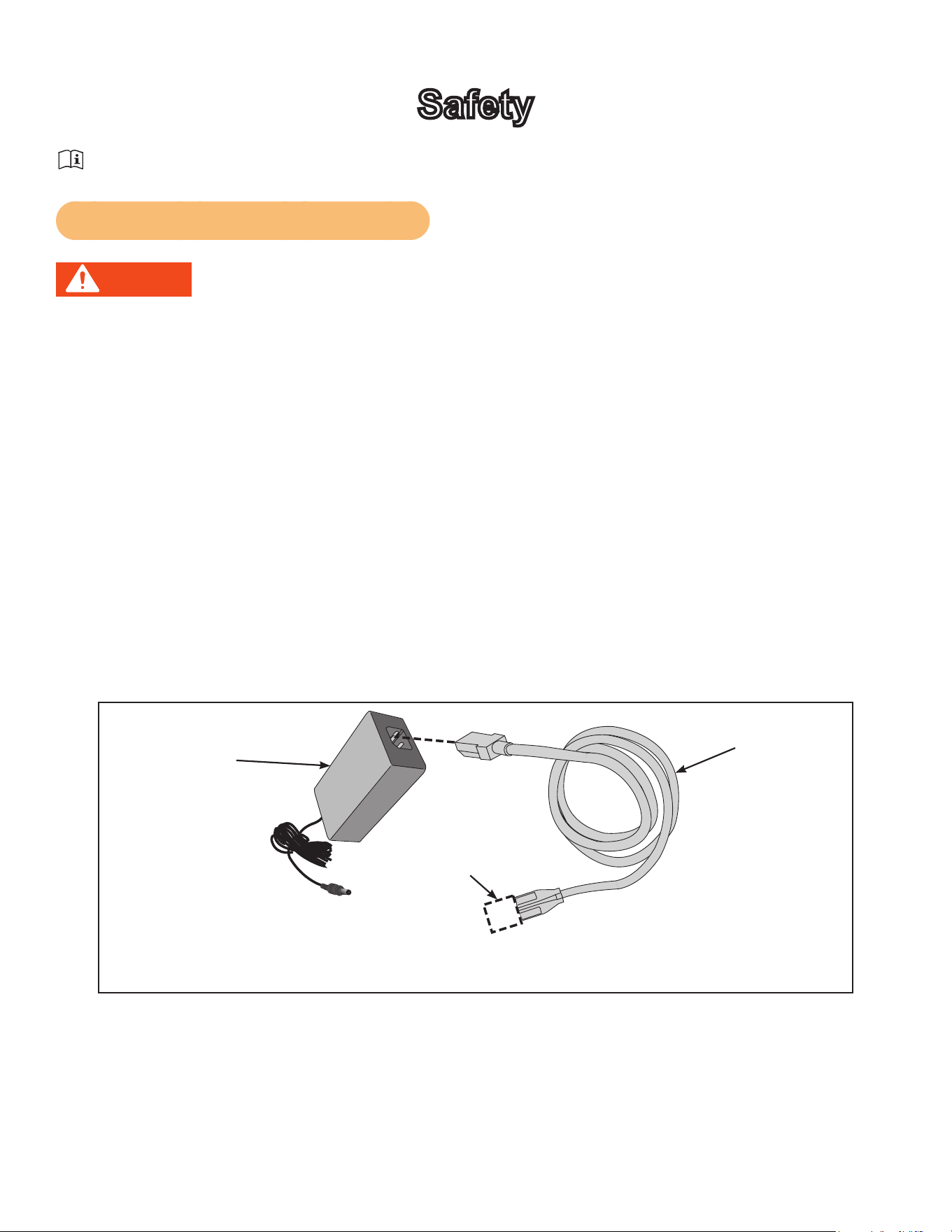
Warnings and Cautions
To replace any worn or damaged decals do one of the following: Visit www.cybexintl.com to shop
for parts online, fax orders to 508-533-5183 or contact Cybex Customer Service at 888-462-9239. If
you are located outside of the USA, call 508-533-4300. For location or part number of labels, see the
parts list and exploded-view diagram on the Cybex web site at www.cybexintl.com.
Warning decals indicate a potentially hazardous situation that could result in death or serious injury if
the precautions are not observed.
Caution decals indicate a potentially hazardous situation, which, if not avoided, could result in minor
or moderate injury.
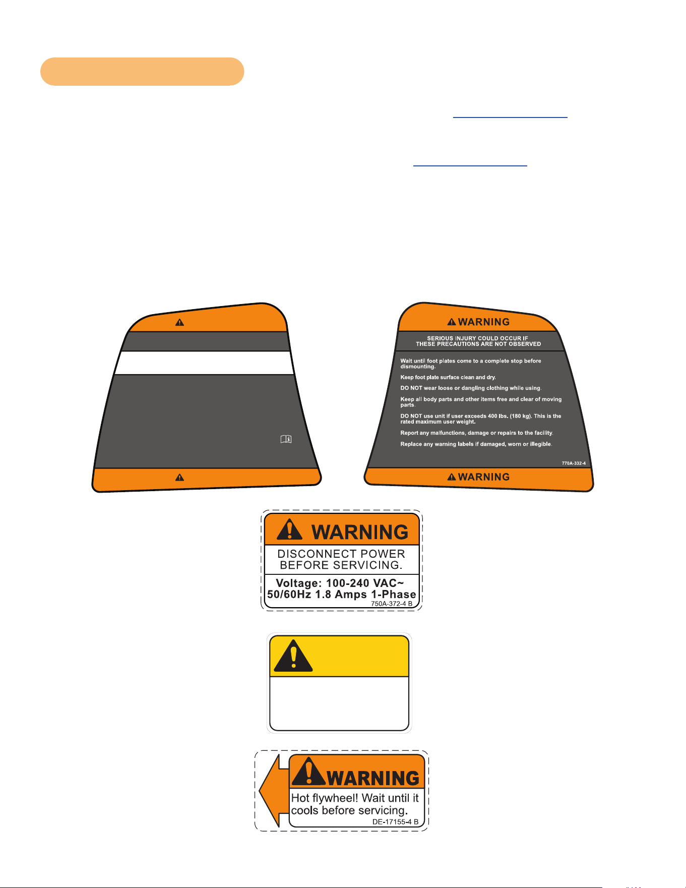
The diagram following the decals show where each decal is located.
DECAL, DISCONNECT POWER
ENGLISH
REL
7-24-08
750A-372-4
125
1:1
OWATONNA
MFG. APPR.
TECH. PUBS. APPR. DAT E
DAT E
REV.
DWG. NO.
SCALE
SIZE
CHECKED BY
DWG. BY
TITLE:
FINISH:
MATERIAL:
B
SHEET
OF
EXCEPT AS NOTED
GENERAL
TOLERANCES:
2 DECIMALS ± .03
3 DECIMALS ± .015
ANGLES ± 1°
FEATURES SHOWN
PERPENDICULAR OR
PARALLEL SHALL BE
SO WITHIN ± 1°
REMOVE ALL BURRS
BREAK SHARP EDGES
.005/.010 R
SURFACE FINISH
INDICATED PER
ANSI B46.1-1985
GENERAL
MACHINING
DIMENSIONS
IN INCHES
DAT E
DAT E
REMOVE CARBURIZATION
AND SCALE FROM LASER
AND PLASMA CUT EDGES
ALL MATERIAL MUST COMPLY TO
EUROPEAN UNION DIRECTIVE
2002/95/EC RoHS (RESTRICTION
OF HAZARDOUS SUBSTANCES)
1 1
B
NOTE: SEE ENGINEERING DRAWING 750A-372-X FOR SPECIFICATIONS.
BB
8-13-08
EML
8-13-08
750A-372-4 B
WARNING
DISCONNECT POWER
BEFORE SERVICING.
Voltage: 100-240 VAC~
50/60Hz 1.8 Amps 1-Phase
2.00
1.25
R .10
4 PLACES
SAFETY ORANGE PMS 152
BLACK TRIANGLE W/ ORANGE
EXCLAMATION POINT, BLACK LETTERS
18 PT ARIAL BOLD FONT
PART NUMBER
6 PT ARIAL TEXT
WHITE BACKGROUND WITH
BLACK 10 PT ARIAL TEXT
WHITE BACKGROUND WITH
BLACK 10 PT ARIAL BOLD TEXT
770A-331-4
SERIOUS INJURY COULD OCCUR IF
THESE PRECAUTIONS ARE NOT OBSERVED
WARNING
WARNING
KEEP ALL CHILDREN 12 AND UNDER AWAY! Teenagers or
disabled must be supervised.
Obtain a medical exam before beginning any exercise program.
Stop exercising if feeling faint, dizzy, or experiencing pain and
consult your physician.
Obtain instruction before using.
Read and understand the Owner's Manual and all warnings
posted on the unit before using.
Use the handrails for support and to maintain balance.
WARNING! Heart rate monitoring systems may be
inaccurate. Over exercise may result in serious injury or
death. If you feel faint stop exercising immediately.
125
1:1
OWATONNA
MFG. APPR.
TECH. PUBS. APPR. DATE
DATE
REV.
DWG. NO.
SCALE
SIZE
CHECKED BY
DWG. BY
TITLE:
FINISH:
MATERIAL:
B
SHEET
OF
EXCEPT AS NOTED
GENERAL
TOLERANCES:
2 DECIMALS ± .03
3 DECIMALS ± .015
ANGLES ± 1°
FEATURES SHOWN
PERPENDICULAR OR
PARALLEL SHALL BE
SO WITHIN ± 1°
REMOVE ALL BURRS
BREAK SHARP EDGES
.005/.010 R
SURFACE FINISH
INDICATED PER
ANSI B46.1-1985
GENERAL
MACHINING
DIMENSIONS
IN INCHES
DATE
DATE
REMOVE CARBURIZATION
AND SCALE FROM LASER
AND PLASMA CUT EDGES
ALL MATERIAL MUST COMPLY TO
EUROPEAN UNION DIRECTIVE
2002/95/EC RoHS (RESTRICTION
OF HAZARDOUS SUBSTANCES)
DE-17155-4
DECAL, WARNING
ENGLISH
1 1
B
JT
7-22-03
WARNING
DE-17155-4 B
Hot flywheel! Wait until it
cools before servicing.
SAFETY ORANGE PMS 152
BLACK TRIANGLE W/ ORANGE
EXCLAMATION POINT, BLACK LETTERS
17.54 PT ARIAL BLACK FONT
WHITE BACKGROUND WITH
BLACK 10.5 PT ARIAL TEXT
PART NUMBER
6.5 PT ARIAL TEXT
125
1:1
OWATONNA
MFG. APPR.
TECH. PUBS. APPR. DATE
DATE
REV.
DWG. NO.
SCALE
SIZE
CHECKED BY
DWG. BY
TITLE:
FINISH:
MATERIAL:
B
SHEET
OF
EXCEPT AS NOTED
GENERAL
TOLERANCES:
2 DECIMALS ± .03
3 DECIMALS ± .015
ANGLES ± 1°
FEATURES SHOWN
PERPENDICULAR OR
PARALLEL SHALL BE
SO WITHIN ± 1°
REMOVE ALL BURRS
BREAK SHARP EDGES
.005/.010 R
SURFACE FINISH
INDICATED PER
ANSI B46.1-1985
GENERAL
MACHINING
DIMENSIONS
IN INCHES
DATE
DATE
REMOVE CARBURIZATION
AND SCALE FROM LASER
AND PLASMA CUT EDGES
ALL MATERIAL MUST COMPLY TO
EUROPEAN UNION DIRECTIVE
2002/95/EC RoHS (RESTRICTION
OF HAZARDOUS SUBSTANCES)
DECAL, CAUTION MOVING PARTS
DE-17219-4
B
1 1
JT
7-22-03
1.80
1.25
R .12
4 PLACES
SAFETY YELLOW PMS 108
BACKGROUND BLACK TRIANGLE
W/ YELLOW EXCLAMATION POINT,
BLACK LETTERS 18.9 PT ARIAL BLACK FONT
WHITE BACKGROUND WITH
BLACK 12 PT ARIAL TEXT
PART NUMBER
6.5 PT ARIAL TEXT
DE-17219-4 B
CAUTION
Moving parts.
Keep hands away
when in use.
DE-17219-4 B
CAUTION
Moving parts.
Keep hands away
when in use.
(SPECS)
MASTER
ARTWORK
DE-17219-4 A
CAUTION
Moving parts.
Keep hands away
when in use.
Cybex Owner’s Manual
8 9
Label Placement
DE-17155-4
DE-17219-4 (2)
770A-332-4
770A-331-4
125
1:1
OWATONNA
MFG. APPR.
TECH. PUBS. APPR. DATE
DATE
REV.
DWG. NO.
SCALE
SIZE
CHECKED BY
DWG. BY
TITLE:
FINISH:
MATERIAL:
B
SHEET
OF
EXCEPT AS NOTED
GENERAL
TOLERANCES:
2 DECIMALS ± .03
3 DECIMALS ± .015
ANGLES ± 1°
FEATURES SHOWN
PERPENDICULAR OR
PARALLEL SHALL BE
SO WITHIN ± 1°
REMOVE ALL BURRS
BREAK SHARP EDGES
.005/.010 R
SURFACE FINISH
INDICATED PER
ANSI B46.1-1985
GENERAL
MACHINING
DIMENSIONS
IN INCHES
DATE
DATE
REMOVE CARBURIZATION
AND SCALE FROM LASER
AND PLASMA CUT EDGES
ALL MATERIAL MUST COMPLY TO
EUROPEAN UNION DIRECTIVE
2002/95/EC RoHS (RESTRICTION
OF HAZARDOUS SUBSTANCES)
DECAL, CAUTION MOVING PARTS
DE-17219-4
B
1 1
JT
7-22-03
1
.80
1
.25
R .12
4 PLACES
SAFETY YELLOW PMS 108
BACKGROUND BLACK TRIANGLE
W/ YELLOW EXCLAMATION POINT,
BLACK LETTERS 18.9 PT ARIAL BLACK FONT
WHITE BACKGROUND WITH
BLACK 12 PT ARIAL TEXT
PART NUMBER
6.5 PT ARIAL TEXT
DE-17219-4 B
CAUTION
Moving parts.
Keep hands away
when in use.
DE-17219-4 B
CAUTION
Moving parts.
Keep hands away
when in use.
(SPECS)
MASTER
ARTWORK
DE-17219-4 A
CAUTION
Moving parts.
Keep hands away
when in use.
750A-372-4

10
Cybex Owner’s Manual
Assembly
Specifications - 770A
Classification S (Studio)
Accuracy A
Length 76.25” (194 cm)
Width 32” (81 cm)
Height: 62.5” (159 cm)
Weight of
Product
404 lbs (183 kg)
Shipping
Weight
429 lbs (195 kg)
Incline Levels 0-20
Resistance
Levels
0-100
Stride Length 24” (61 cm) xed length.
Workouts
Quick Start, ve workout groups, seven workouts, three heart rate workouts, and
two power workouts
Console
Features
Upper console: LED or E3 View Monitor. Displays Cal/Hr, Distance, Strides per
Minute, Calories, Watts, METs and BPM.
Lower console: Two numeric displays for incline, time, resistance and level.
Fan, iPod connector, CardioTouch screen, accessory trays and water bottle holder
Heart Rate
Features
Built-in wireless heart rate receiver (transmitter not included) and contact heart rate
monitoring.
Frame Colors
Standard: White Texture, Black Texture, Metaltone Gold, Black Chrome, Platinum
Sparkle.
Custom: Unlimited colors available.
Resistance
Range
0-900 watt.
Maximum
User Weight
400 lbs. (181 kg).
Power Rating Self powered or 100 - 240 VAC~, 50/60 Hz, 1.8A, 1-phase.
Options AC Power Adapter, E3 View Monitor.
The dimensions stated in the installation instructions are the recommended minimum dimensions as
set forth by the manufacturer. The actual area for access and passage shall be the responsibility of
the facility and should take into account any required local codes or regulations.

11
Cybex Owner’s Manual
Specifications - 770AT
Classification S (Studio)
Accuracy A
Length 76.25” (194 cm)
Width 36.28” (92 cm)
Height: 62.5”(159 cm)
Weight of
Product
412 lbs. (187 kg.)
Shipping
Weight
437 lbs. (198 kg.)
Incline Levels 0-20
Resistance
Levels
0-100
Stride Length 24” (61 cm) xed length.
Workouts
Quick Start, ve workout groups, seven workouts, three heart rate workouts, and
two power workouts
Console
Features
Upper console: LED or E3 View Monitor. Displays Cal/Hr, Distance, Strides per
Minute, Calories, Watts, METs and BPM.
Lower console: Two numeric displays for incline, time, resistance and level.
Fan, iPod connector, CardioTouch screen, accessory trays and water bottle holder.
Heart Rate
Features
Built-in wireless heart rate receiver (transmitter not included) and contact heart rate
monitoring.
Frame Colors
Standard: White Texture, Black Texture, Metaltone Gold, Black Chrome, Platinum
Sparkle.
Custom: Unlimited colors available.
Resistance
Range
0-900 watt.
Maximum
User Weight
400 lbs. (181 kg).
Power Rating Self powered or 100 - 240 VAC~, 50/60 Hz, 1.8A, 1-phase.
Options AC Power Adapter, E3 View Monitor.
The dimensions stated in the installation instructions are the recommended minimum dimensions as
set forth by the manufacturer. The actual area for access and passage shall be the responsibility of
the facility and should take into account any required local codes or regulations.

12
Cybex Owner’s Manual
Environment and Storage
Humidity and Static Electricity
The unit is designed to function normally in an environment with a relative humidity range of 30% to
75%. The unit can be shipped and stored in a relative humidity range of 10% to 90%.
Dry air may cause static electricity. During workout, user may experience a shock due to build-up
of static electricity on the body and the discharge path of the unit. If static electricity is experienced,
increase humidity to a comfortable level through the use of a humidier.
Do not install, use, or store the unit in an area of high humidity, such as in the vicinity of a steam
room, sauna, indoor pool or outdoors. Exposure to extensive water vapor, chlorine and/or bromine
could adversely affect the electronics as well as other parts of the unit.
Temperature
The unit is designed to function normally in an environment with an ambient temperature range of 50°
F (10° C) to 104° F (40° C). The unit can be shipped and stored in an environment with an ambient
temperature range of 32° F (0° C) to 140° F (60° C).
Choosing and Preparing Site
Before assembling the unit, verify chosen site meets the following criteria:
• Area is well lit and well ventilated.
• Surface is structurally sound and properly leveled.
Place a 3/4” (1.9 cm) thick wood base under unit to protect carpeting.
Area allows for ample access and passage clearance around unit or for emergency dismount.
Minimum clearance is 19.7 inches (0.5 meters) on at least one side of unit and also behind unit.
Minimum clearance fo 12” (30 cm) between units for proper wireless heart rate signal operation.
Electrical Power Requirements
The E3 View Monitor is supplied with a power cord, The AC power kit is optional.
• Verify unit is connected to an outlet having the same conguration as the plug.
• Verify connection is a grounded circuit.
• Do not use a ground-plug adapter to adapt the 3-prong power cord to a non-grounded electrical
outlet.
• Use Cybex supplied optional AC power kit only. Consult an electrician with any questions.
• Ensure outlets used by this product meet all local and federal building codes.

13
Cybex Owner’s Manual
770A Assembly Procedure
Tools Required
• Phillips screwdriver
• Stubby Phillips screwdriver
• 3/16” Allen wrench (supplied)
• 7/32” Allen wrench (supplied)
• 9/16” Open end wrench (2)
The words “left” and “right” denote the user’s orientation.
Two people will be required for this procedure.
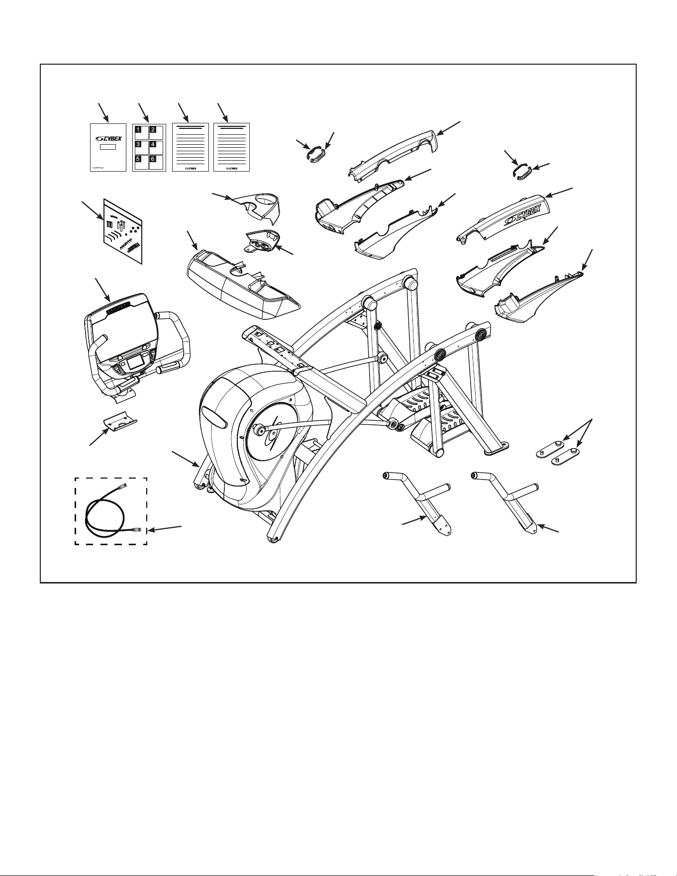
Read and understand all instructions thoroughly before assembling this unit. Check all items
carefully. If there is damage, see the Customer Service section of this manual for proper procedure to
return, replace, or reorder parts.
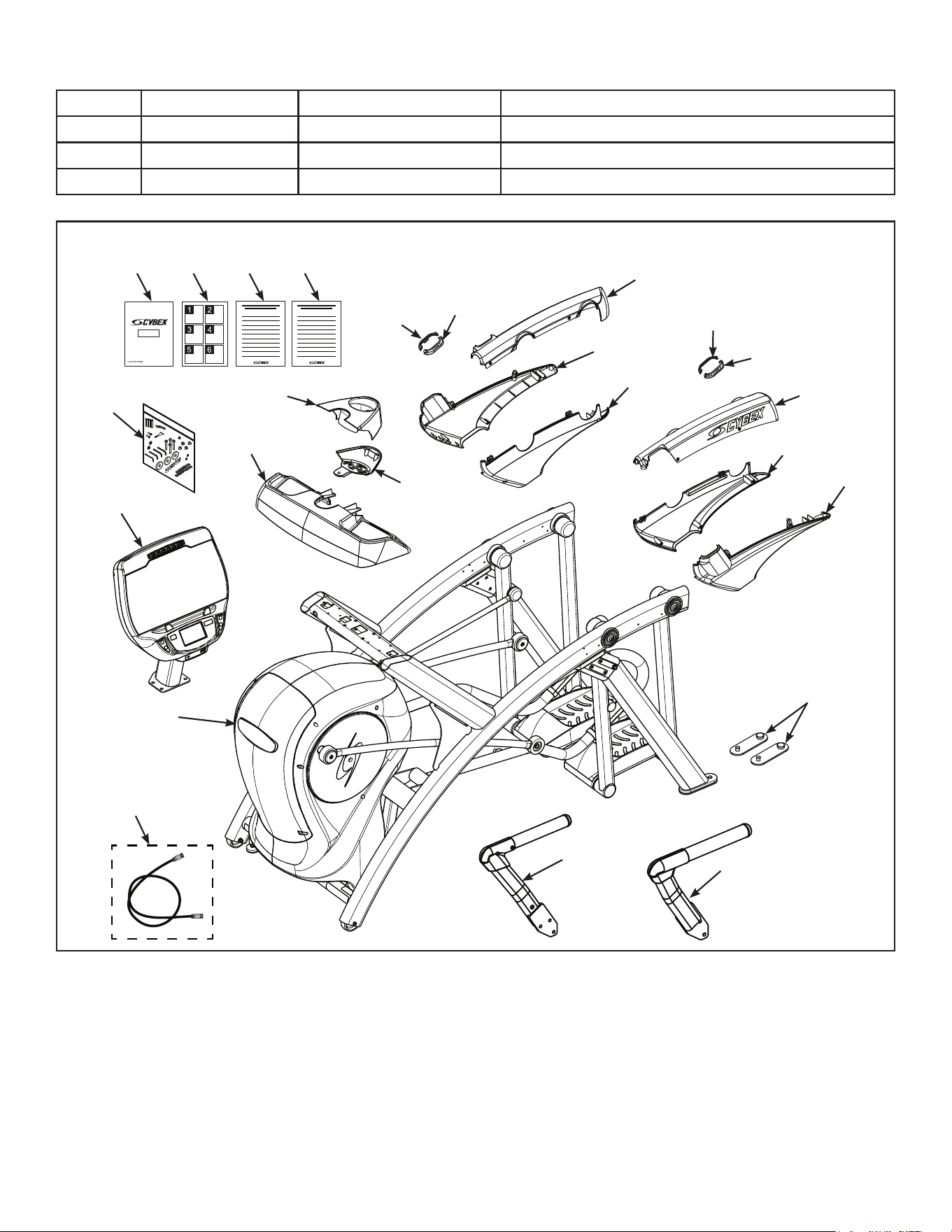
Item Quantity Part Number Description
1 1 Varies Base assembly
2 1 Varies Console assembly
3 2 12090-322 Foot pad
4 1 NA Handle, Right
5 1 NA Handle, Left
6 1 770A-316 Base, Accessory tray
7 1 770A-317 Cover, Top, Accessory tray
8 1 770A-318 Cover, Bottom, Accessory tray
9 1 770A-322 Cover, Rear, Top, Right
10 1 770A-323 Cover, Rear, Outer, Right
11 1 770A-324 Cover, Rear, Inner, Right
12 1 770A-319 Cover, Rear, Top, Left
13 1 770A-321 Cover, Rear, Inner, Left
14 1 770A-320 Cover, Rear, Outer, Left
15 1 770A-341 Collar, Outer, Right
16 1 770A-340 Collar, Inner, Right
17 1 770A-334 Collar, Inner, Left
18 1 770A-335 Collar, Outer, Left
19 1 NA Hardware pack
20 1 5770-X Owner’s Manual
21 1 770A-404 Assembly poster
22 1 770A-415 Commercial Arc warranty sheet
23 1 770A-416 Consumer Arc warranty sheet
24 1 770A-310 Bracket, Lower, Display mount
25 1 770A-427 Cable, 6’, Coax (E3 View Monitor option)
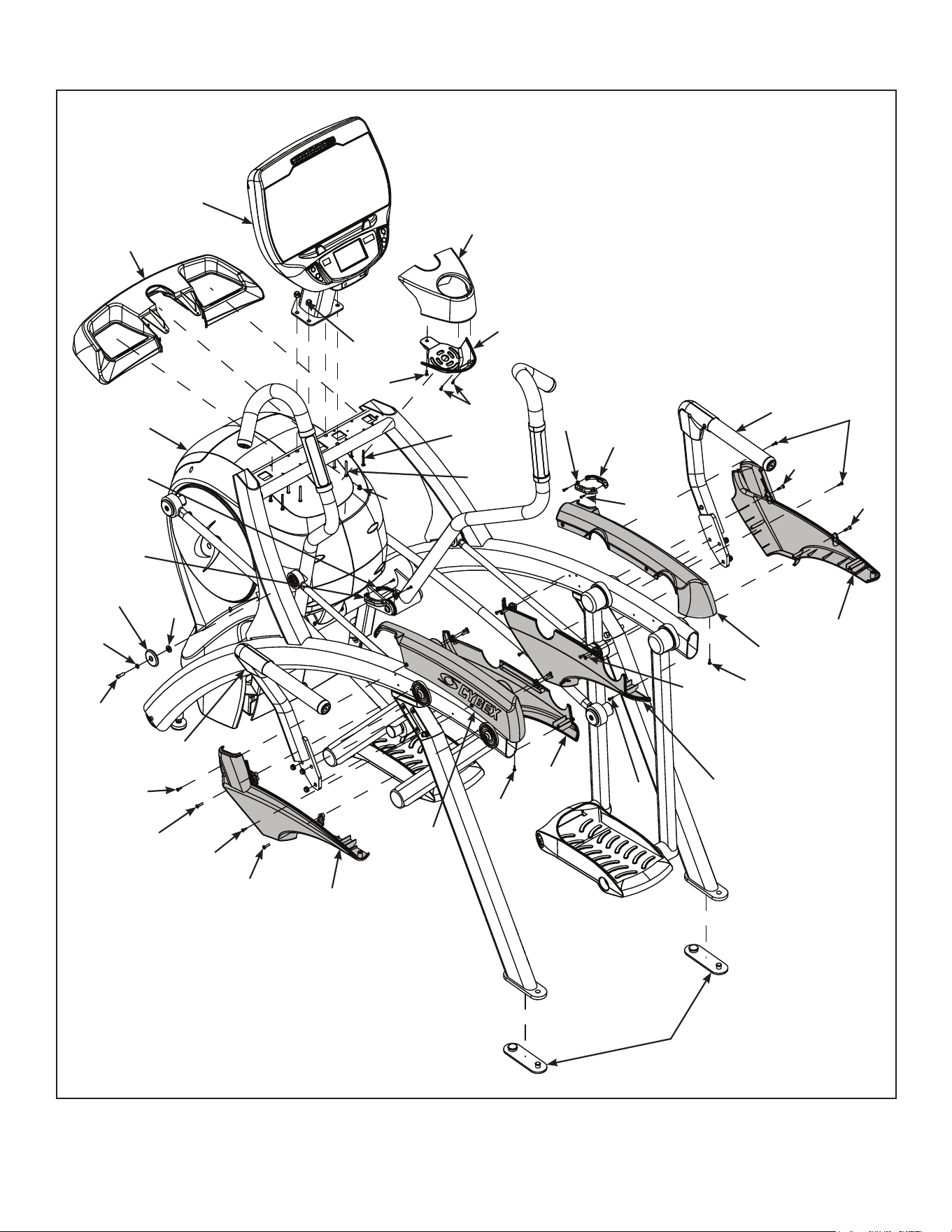
14
Cybex Owner’s Manual
#9
#10
#15
#13
#17
#11
#16
#14
#18
#12
#7
#2
#3
#6
#4
#5
#19
#20 #21 #22 #23
#24
#25
#1
#8
15
Cybex Owner’s Manual
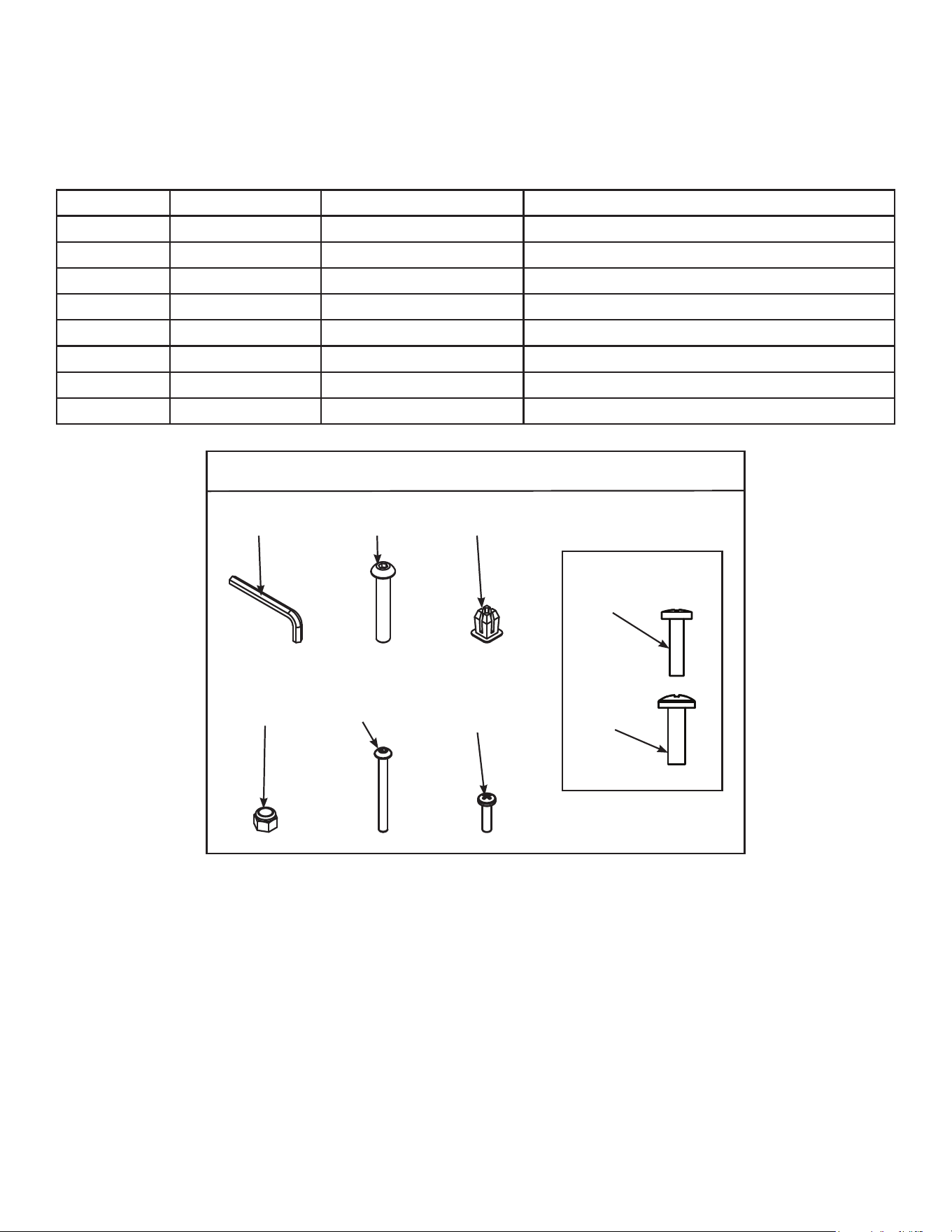
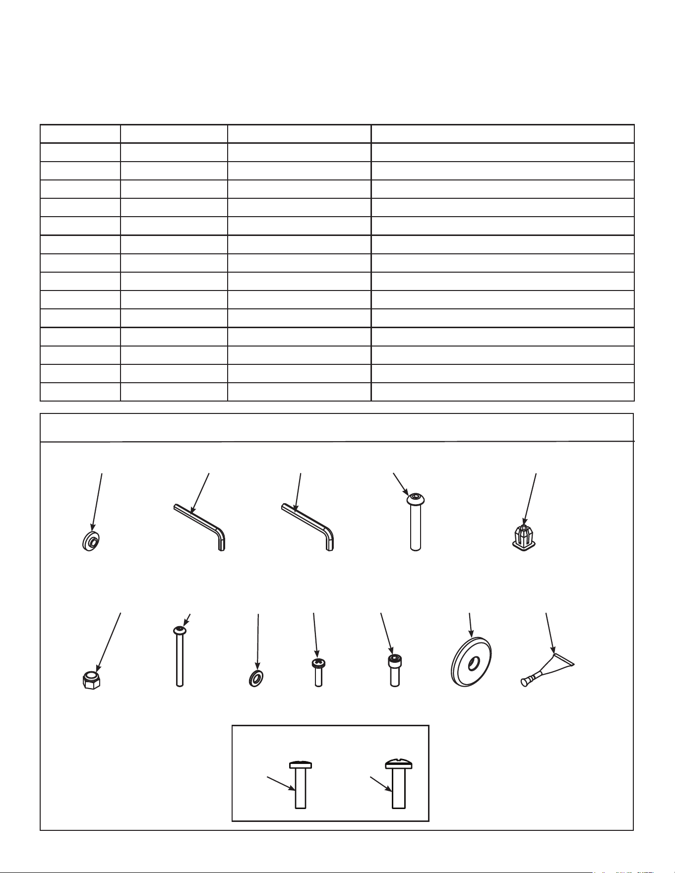
Verify contents of hardware pack
See hardware pack listings and hardware pack contents. See Customer Service for contact
information if any parts are missing.
Item Quantity Part Number Description
26 1 BK030204 7/32” Allen Wrench
27 4 HC700430 BHSCS .375-16 x 2.50”
28 1 HF540200 Grommet, Nylon
29 4 HN704901 Locknut, .375-16 Nylon
30 4 HT592526 Tap Sc 10-12 x 2.00 Pn Hd Phil
31 6 HT532512 Screw, Pan Head Phillips, #6 x .50”
32 19 HT552512 Screw, Pan Head Phillips, 8-16 x .50”
33 8 HT572515 Screw, Pan Head Phillips, 10-24 x .75”
770A Hardware
#26
#30
#27
#31
#28
1:1
#32
#29
#33
16
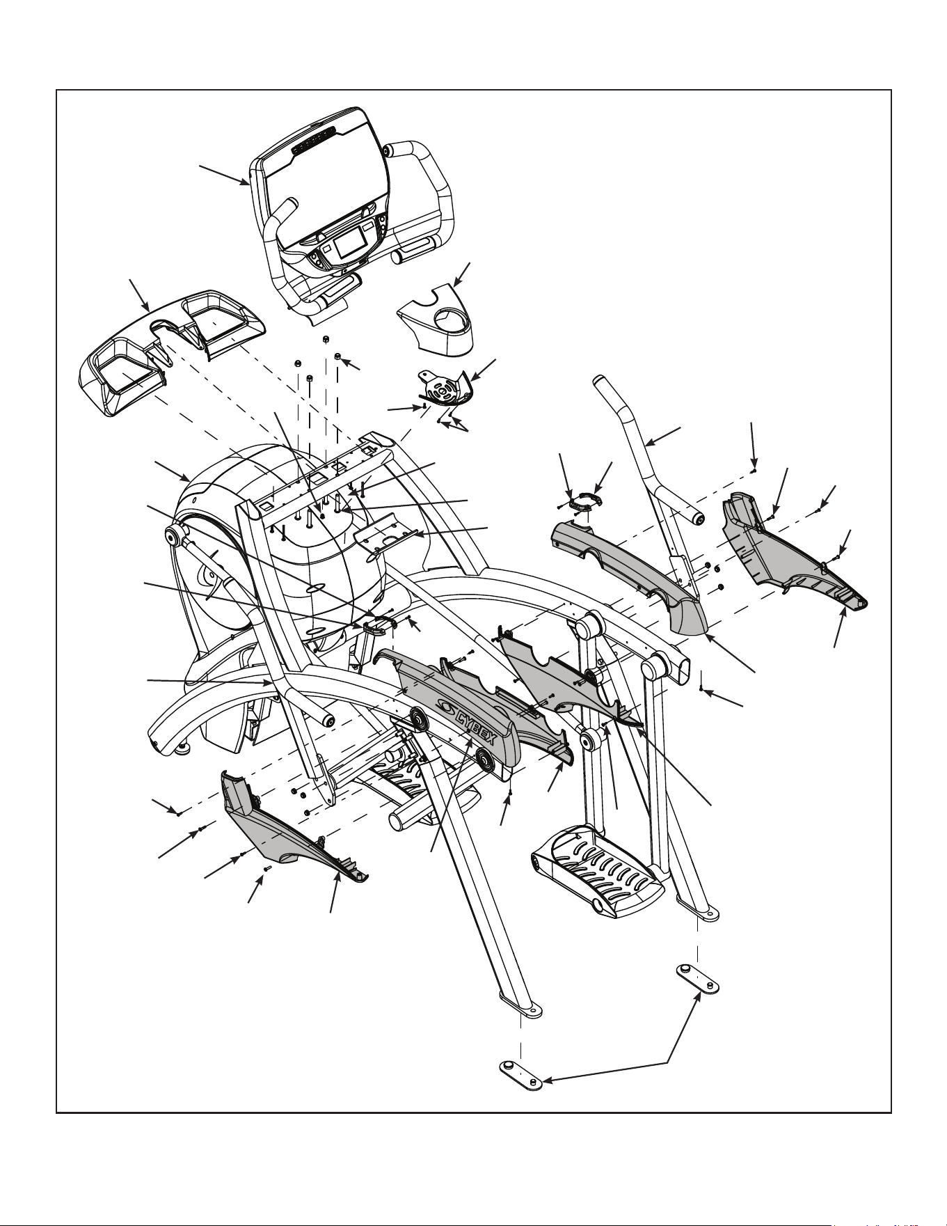
Cybex Owner’s Manual
#9
#10
#15
#13
#17
#11
#16
#14
#18
#31
#30
#27
#24
#32
#33
#32
#33
#32
#32
#32
#31
#29
#28
#33
#12
#7
#2
#3
#6
#4
#32
#33
#32
#33
#5
#1
#8
17
Cybex Owner’s Manual
Lift and move unit
1. Remove large bolts and shipping supports. Keep package material on linkage arms at this
time. This will protect the paint from scratching during assembly.
2. Grasp each rear support leg rmly and lift with one person on each side.
3. Lift the lower rear support legs using proper lifting methods so the front transport wheels are
able to roll on floor.
4. Move unit to intended location.
5. Lower rear support legs.
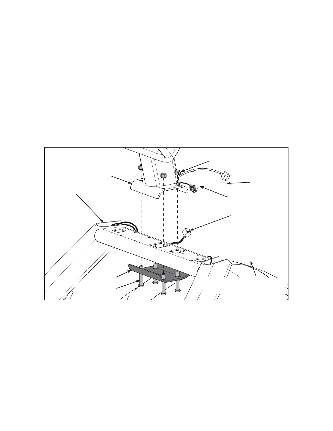
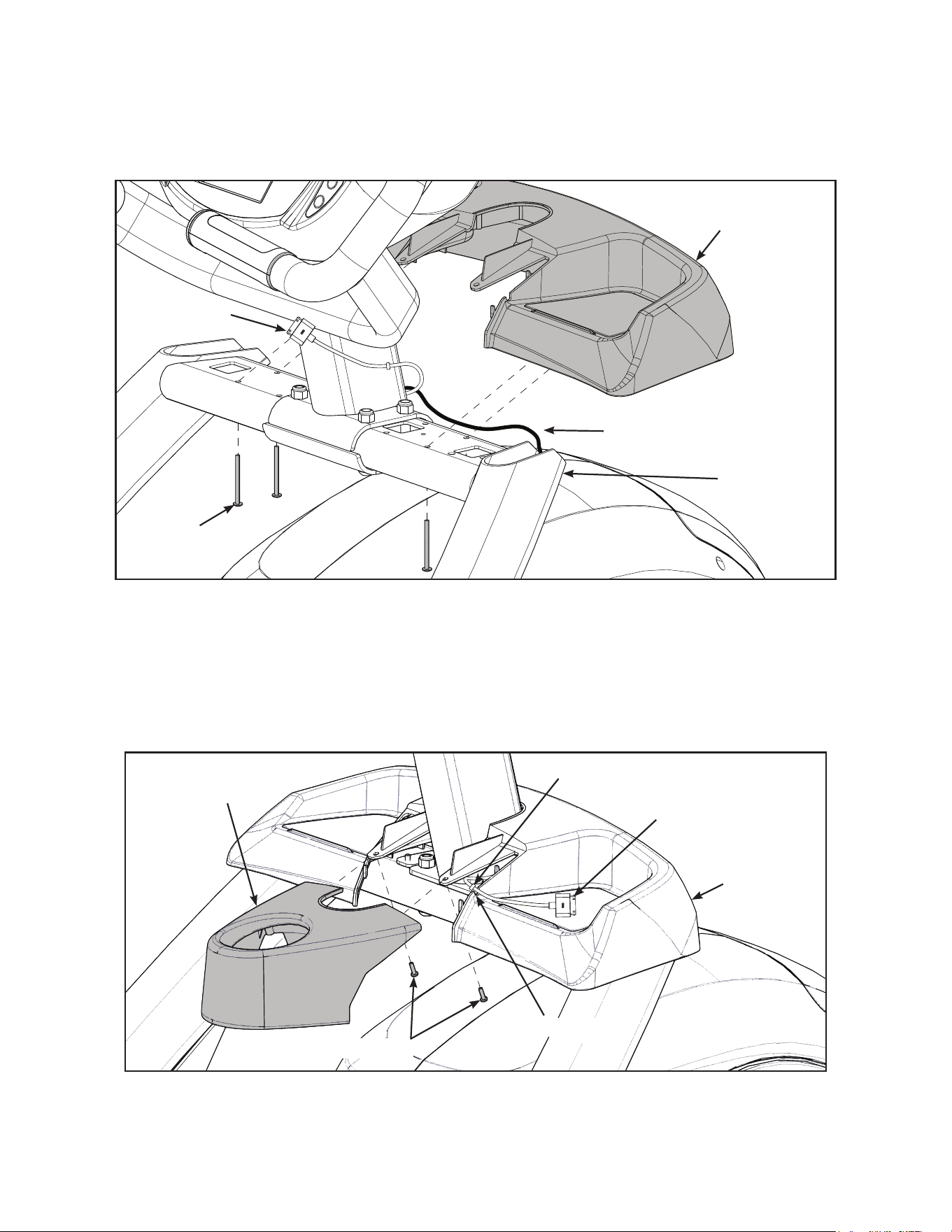
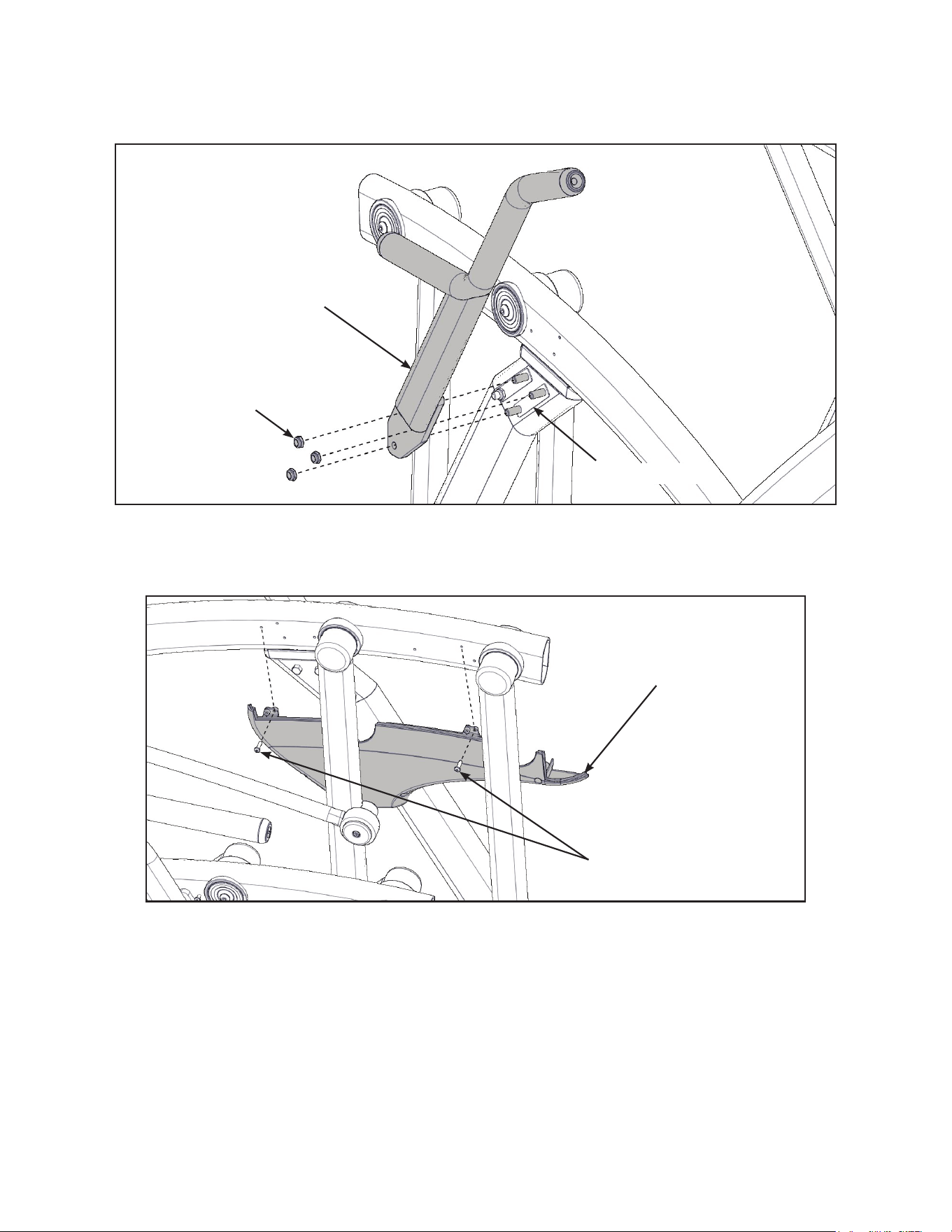
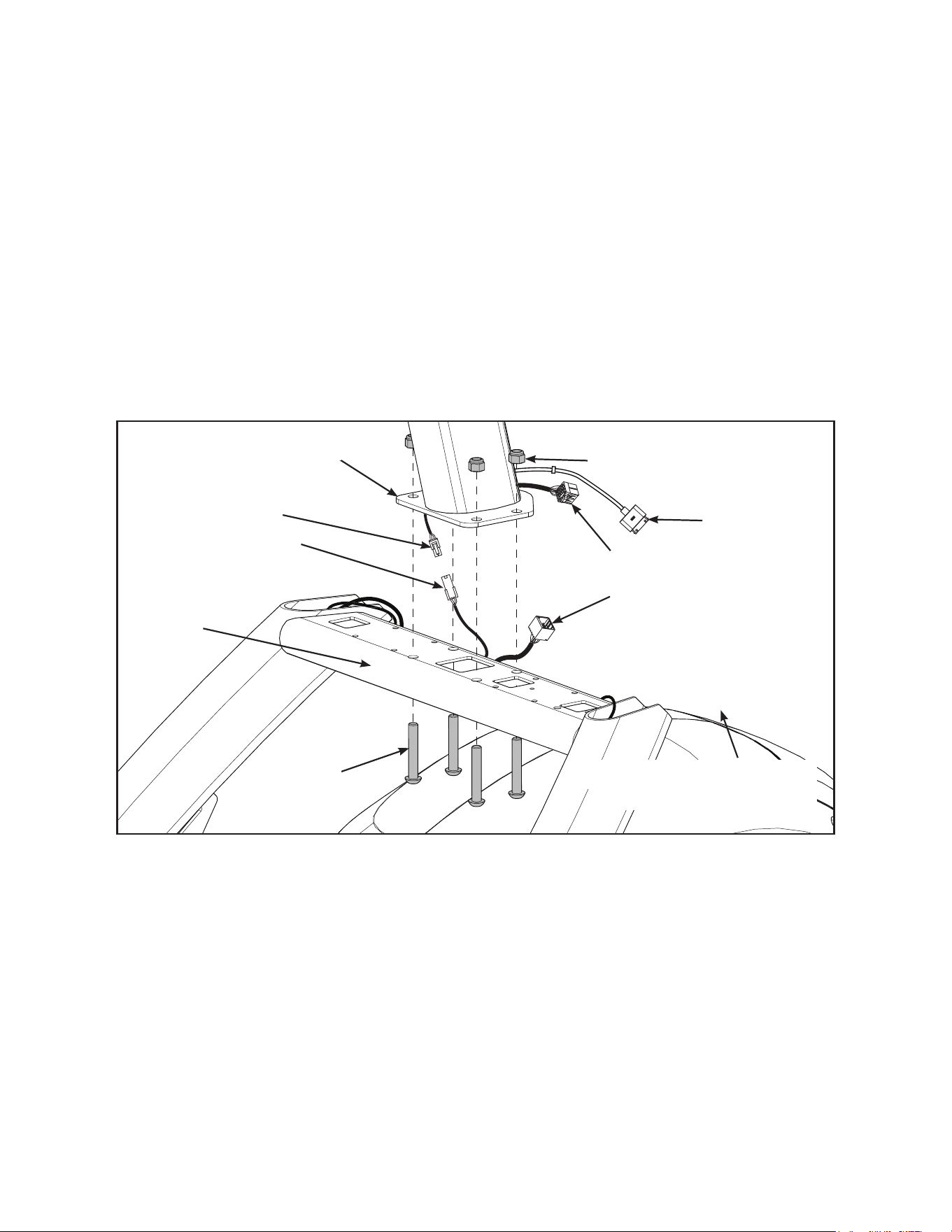
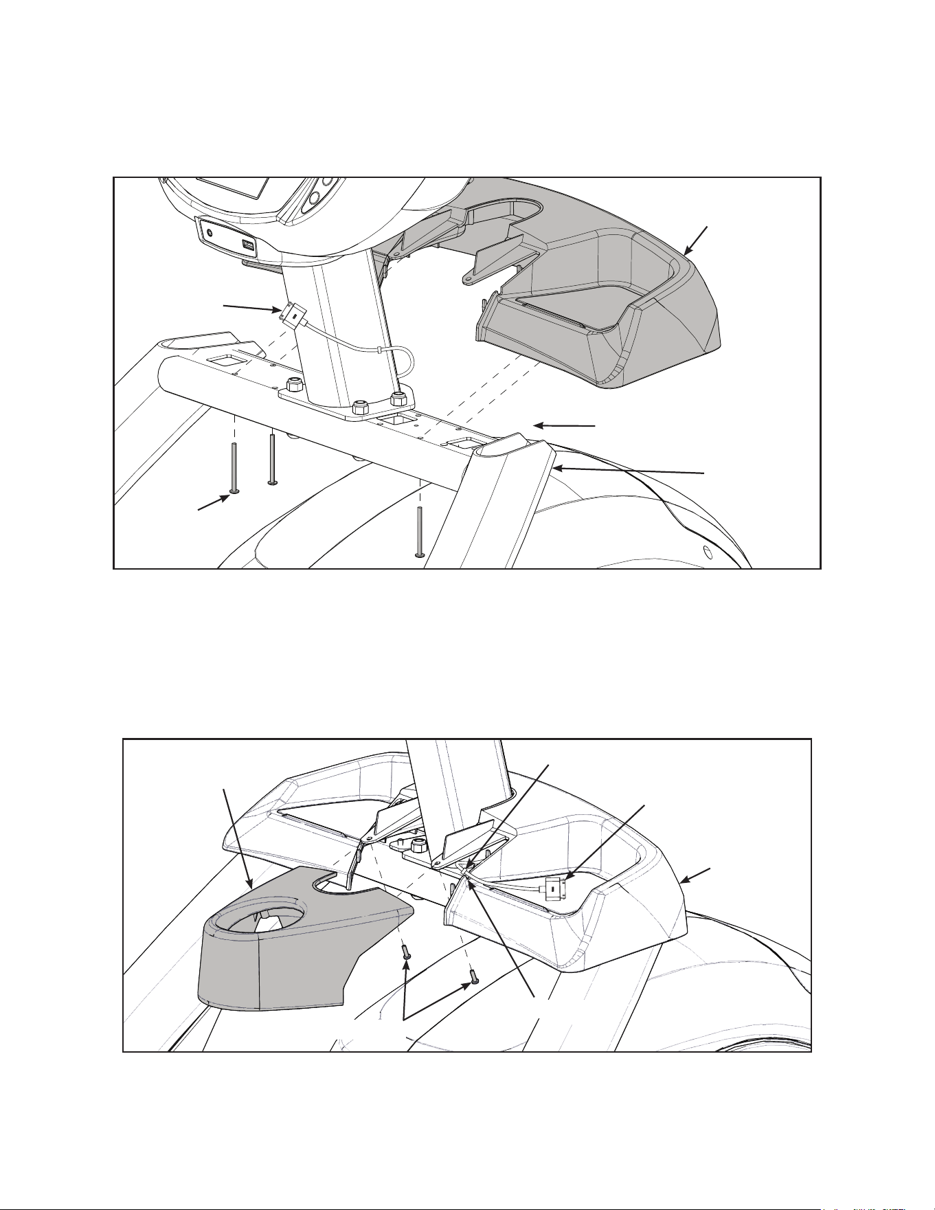
Attach 770A console assembly.
1. Place the console into position on the frame. Do not pinch cables while lowering the console.
Upper Display
Cable
Console
Locknuts (4)
Bolts (4)
Lower
Bracket
iPod
Cable
Frame
Lower Display
Cable
Coax Cable
(E3 View Monitor option)
2. Insert (from underneath) the lower bracket and four bolts into the frame and console.
3. Thread the four locknuts onto the bolts by hand.
4. Tighten the four bolts and locknuts with a 7/32” Allen wrench and a 9/16” open-end wrench.
5. Plug the upper display cable into the lower display cable.

18
Cybex Owner’s Manual
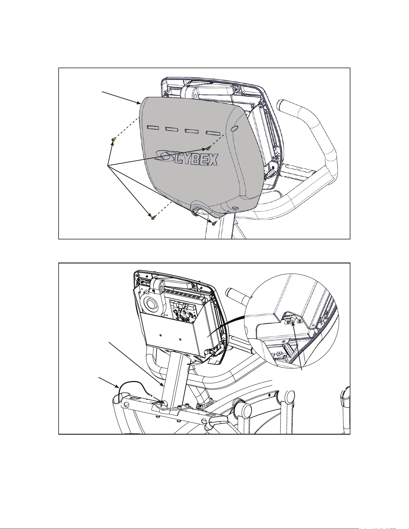
Install coax cable (E3 View Monitor option)
1. Remove four screws securing back cover to the console using a Phillips screwdriver.
Screws (4)
Back
Cover
2. Route coax cable up through console support tube.
E3 View Monitor
Coax Connection
Coax
Cable
Console
Support
Tube
3. Install coax cable into the E3 View Monitor coax connector and tighten threaded connector.
4. Install four screws securing back cover to console using a Phillips screwdriver.
19
Cybex Owner’s Manual
Install accessory tray base
1. Place the accessory tray in position on the frame and route the iPod cable towards the back of
the unit. Do not pinch optional coax cable.
Coax Cable
(E3 View Monitor option)
Frame
Screws
(4)
iPod Cable
Accessory
Tray Base
2. Install the four screws using a stubby Phillips screwdriver.
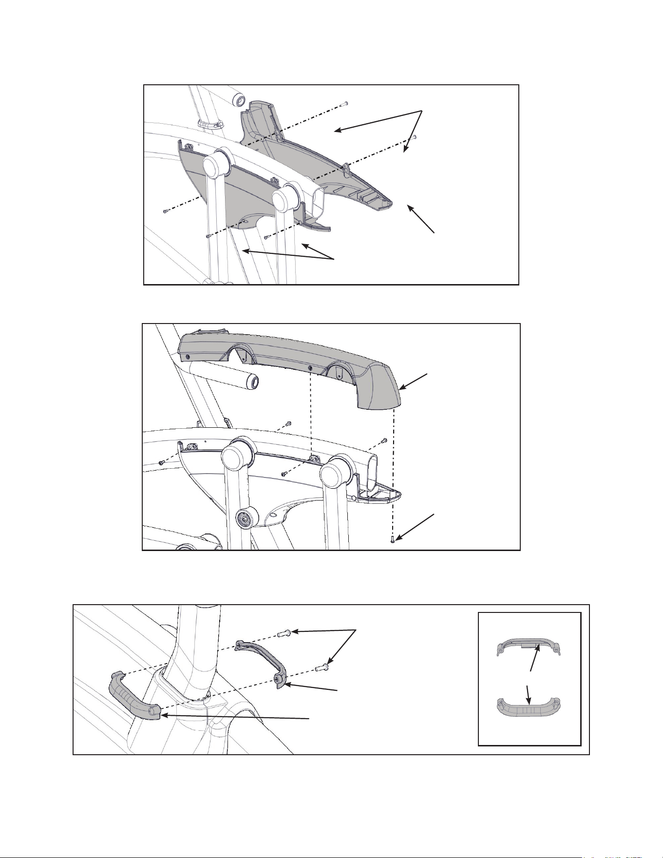
Install accessory tray top
1. Place the accessory tray top in position on the accessory tray base and route the iPod cable
through the notch in the accessory tray. Place the iPod cable strain relief on the inside edge of
the notch in the accessory tray.
Screws (2)
iPod Cable
Strain Relief
Notch
Accessory
Tray Top
Accessory
Tray Base
2. Install the two screws using a stubby Phillips screwdriver.
20
Cybex Owner’s Manual
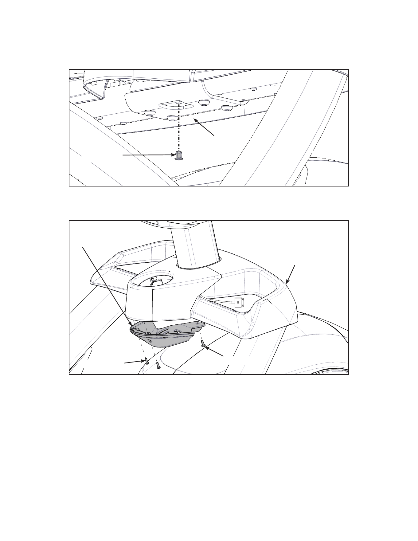
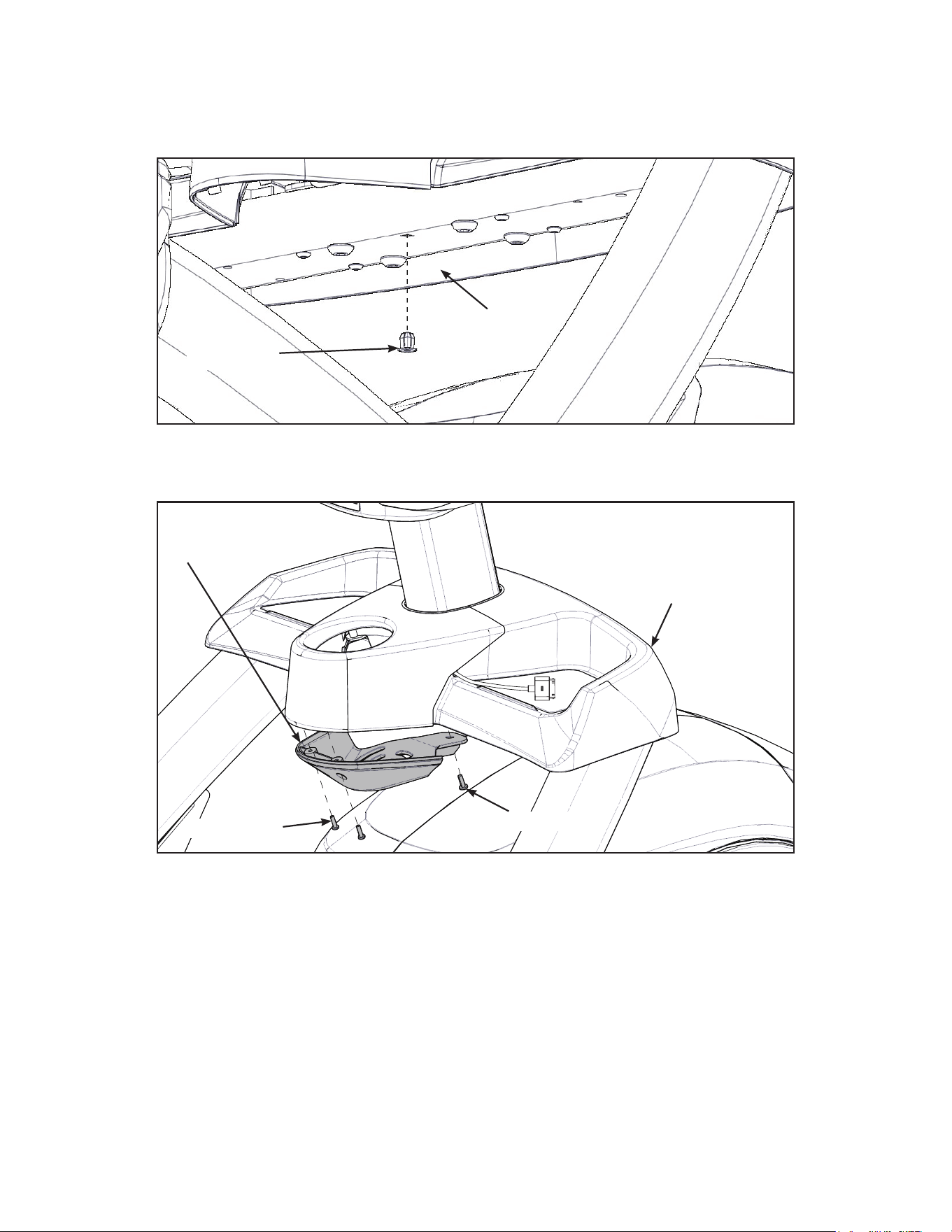
Install accessory tray bottom
Install the grommet to the frame.
Frame
Grommet
Install the accessory tray bottom to the accessory tray base with three screws using a Phillips
screwdriver.
Screws (2)
Screw
Accessory
Tray Base
Accessory
Tray Bottom
21
Cybex Owner’s Manual
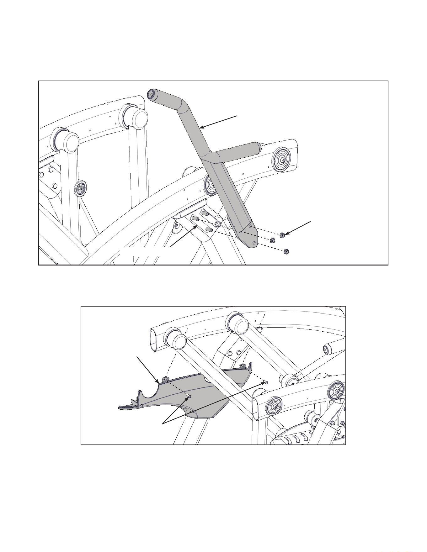
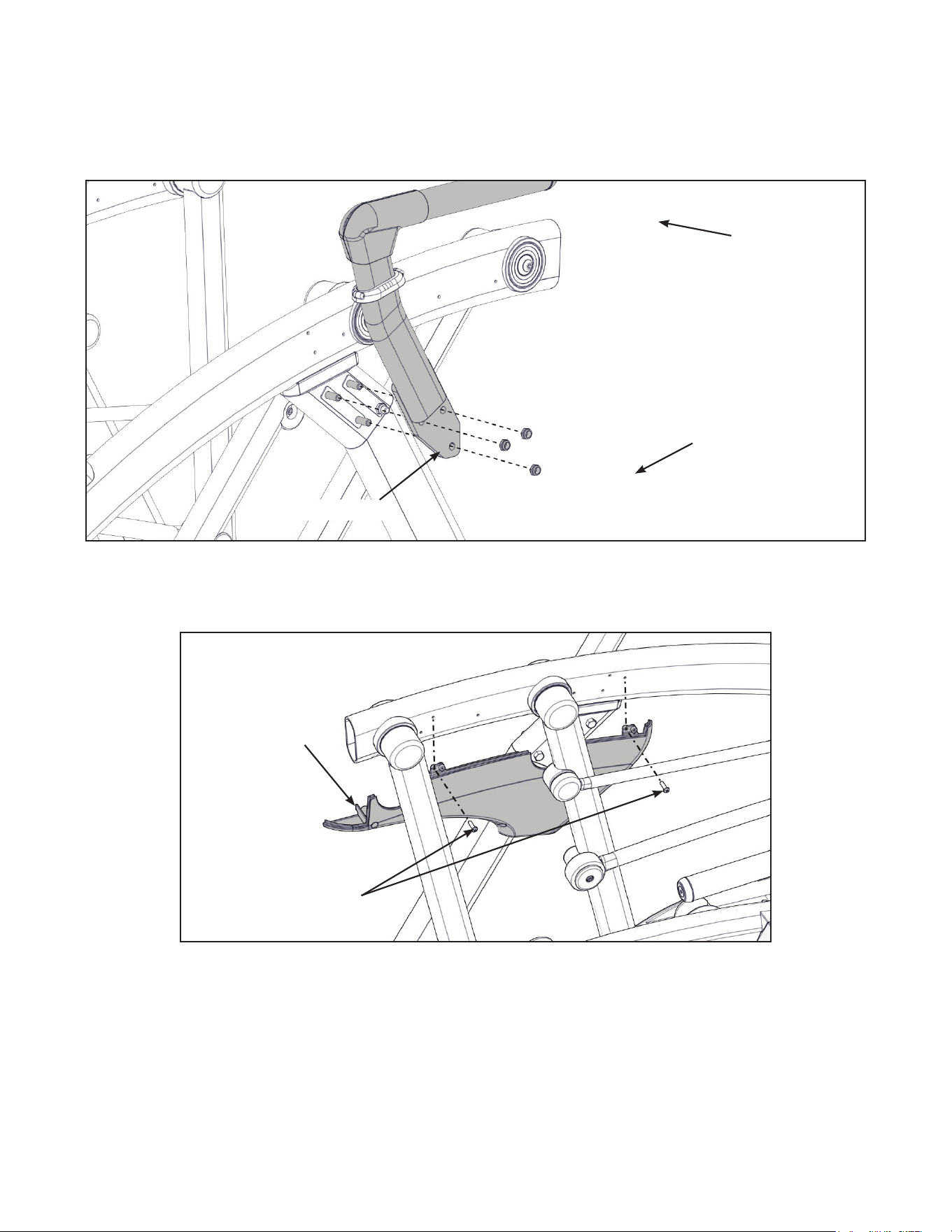
Installhandrails.
1. Remove three locknuts from the left support leg using two 9/16” open end wrenches. Keep the
two spacers in place.
Locknuts (3)
Spacers (2)
Left Handle
2. Install the left handle and three locknuts using two 9/16” open end wrenches.
3. Install the left inner rear cover with two screws using a Phillips screwdriver.
Screws (2)
Left Inner
Rear Cover
22
Cybex Owner’s Manual
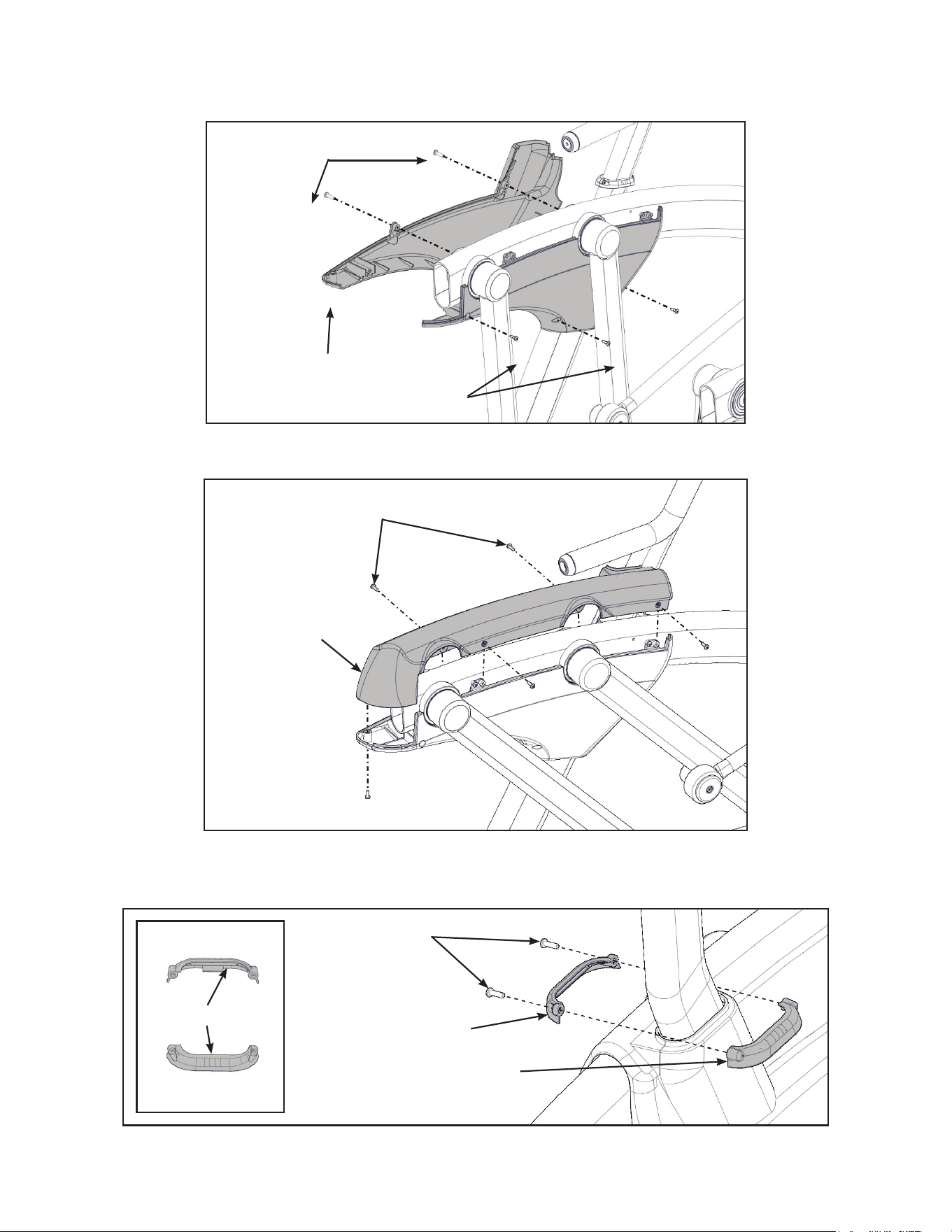
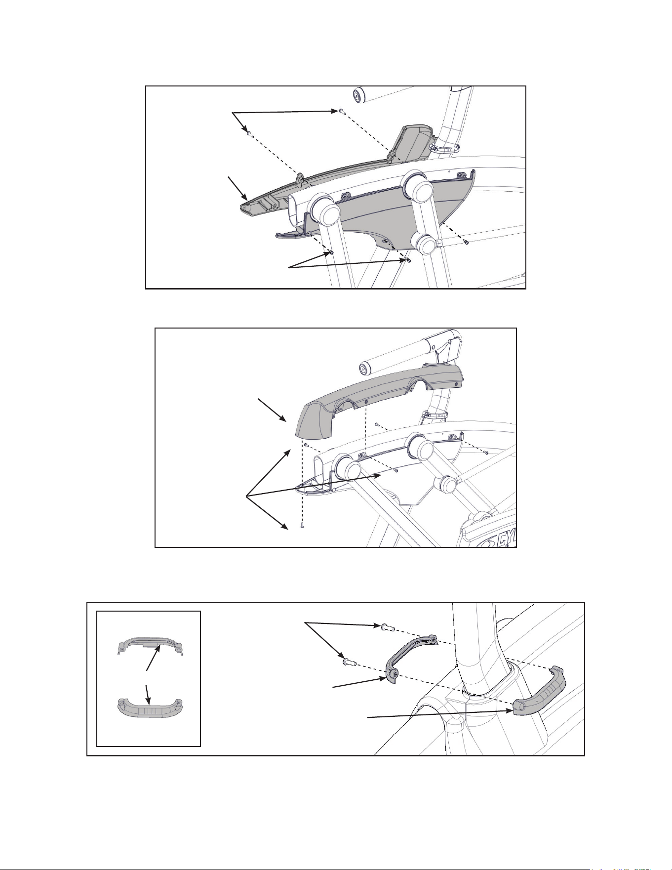
4. Install the left outer rear cover with ve screws using a Phillips screwdriver.
Screws (2)
Screws (3)
Left Outer
Rear Cover
5. Install the left top rear cover with ve screws using a Phillips screwdriver.
Screws (5)
Left Top
Rear Cover
6. Install the left inner and outer collars with two screws using a Phillips screwdriver. Collars are
marked with an “L” on the inside and have a left and right side.
Screws (2)
Left Outer Collar
Left Inner Collar
“L”
23
Cybex Owner’s Manual
7. Remove three locknuts from the right support leg using two 9/16” open end wrenches. Keep
the two spacers in place.
Locknuts (3)
Spacers (2)
Right Handle
8. Install the right handle and three locknuts using two 9/16” open end wrenches.
9. Install the right inner rear cover with two screws using a Phillips screwdriver.
Screws (2)
Right Inner
Rear Cover
24
Cybex Owner’s Manual
10.Install the right outer rear cover with ve screws using a Phillips screwdriver.
Screws (2)
Screws (3)
Right Outer
Rear Cover
11.Install the right top rear cover with ve screws using a Phillips screwdriver.
Screws (5)
Right Top
Rear Cover
12.Install the right inner and outer collars with two screws using a Phillips screwdriver. Collars are
marked with an “R” on the inside and have a left and right side.
Screws (2)
Right Outer Collar
Right Inner Collar
“R”
25
Cybex Owner’s Manual
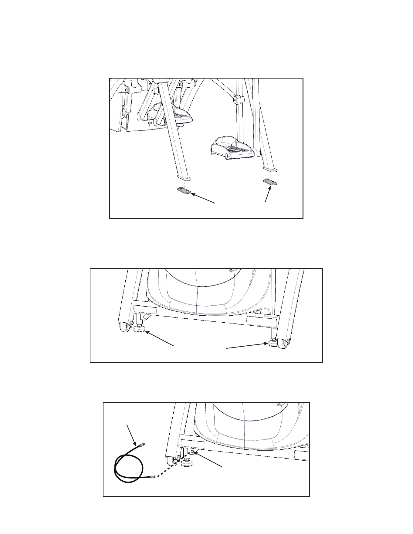
Attach foot pads
Have one person lift the unit while a second person places a foot pad under each of the two back
feet.
Foot Pads (2)
Level unit
Conrm unit is on a level surface. If not, use a 9/16” open-end wrench to adjust the leveling feet up or
down.
Leveling Feet
Install coax cable (E3 View Monitor option)
Install 6’ coax cable to the coax cable connector in base of unit.
6’ Coax
Cable
Coax Cable
Connector

26
Cybex Owner’s Manual
Visually inspect unit
1. Carefully remove any package material from arms and rest of unit.
2. Carefully examine the unit to ensure assembly is correct and complete.
770AT Assembly Procedure
Tools Required
• Phillips screwdriver
• Stubby Phillips screwdriver
• 3/16” Allen wrench (supplied)
• 7/32” Allen wrench (2) (supplied)
• 9/16” Open end wrench (2)
The words “left” and “right” denote the user’s orientation.
Two people will be required for this procedure.
Read and understand all instructions thoroughly before assembling this unit. Check all items
carefully. If there is damage, see the Customer Service section of this manual for proper procedure to
return, replace, or reorder parts.
Item Quantity Part Number Description
1 1 Varies Base assembly
2 1 Varies Console assembly
3 2 12090-322 Foot pad
4 1 NA Handle, Right
5 1 NA Handle, Left
6 1 770A-316 Base, Accessory tray
7 1 770A-317 Cover, Top, Accessory tray
8 1 770A-318 Cover, Bottom, Accessory tray
9 1 770A-322 Cover, Rear, Top, Right
10 1 770A-323 Cover, Rear, Outer, Right
11 1 770A-324 Cover, Rear, Inner, Right
12 1 770A-319 Cover, Rear, Top, Left
13 1 770A-321 Cover, Rear, Inner, Left
14 1 770A-320 Cover, Rear, Outer, Left
15 1 770A-341 Collar, Outer, Right
16 1 770A-340 Collar, Inner, Right
17 1 770A-334 Collar, Inner, Left
18 1 770A-335 Collar, Outer, Left
19 1 NA Hardware pack
20 1 5770-X Owner’s Manual
21 1 770AT-316 Assembly poster
27
Cybex Owner’s Manual
Item Quantity Part Number Description
22 1 770A-415 Commercial Arc warranty sheet
23 1 770A-416 Consumer Arc warranty sheet
24 1 770A-427 Cable, 6’, Coax (E3 View Monitor option)
#9
#10
#15
#13
#17
#11
#16
#14
#18
#12
#7
#2
#3
#6
#4
#5
#19
#20 #21 #22 #23
#1
#8
#24
28
Cybex Owner’s Manual
Verify contents of hardware pack
See hardware pack listings and hardware pack contents. See Customer Service for contact
information if any parts are missing.
Item Quantity Part Number Description
25 2 600A-311 Flange Spacer
26 1 BK030201 3/16” Allen Wrench
27 2 BK030204 7/32” Allen Wrench
28 4 HC700428 BHSCS .375-16 x 2.25”
29 1 HF540200 Grommet, Nylon
30 4 HN704901 Locknut, .375-16 Nylon
31 4 HT592526 Tap Sc 10-12 x 2.00 Pn Hd Phil
32 2 HS307601 Washer, Flat .281 ID x .500 OD x .062”
33 6 HT532512 Screw, Pan Head Phillips, #6 x .50”
34 19 HT552512 Screw, Pan Head Phillips, 8-16 x .50”
35 8 HT572515 Screw, Pan Head Phillips, 10-24 x .75”
36 2 HX622815 SHCS .250-20 UNC-3A SS
37 3 PL-16535 Linkage Rod Cap 2.00 OD (1 extra)
38 1 YA000201 Loctite
770AT Hardware
#25
#31
#26
#32
#27 #28
#35
#29
#37#36
#30
#38
#33 #34
1:1
29
Cybex Owner’s Manual
#9
#10
#15
#13
#17
#36
#38
#32
#37
#25
#11
#16
#14
#18
#33
#31
#28
#34
#35
#34
#35
#34
#34
#35
#34
#33
#30
#29
#35
#12
#7
#2
#3
#6
#4
#5
#1
#8
#34
#35
#35
30
Cybex Owner’s Manual
Lift and move unit
1. Remove large bolts and shipping supports. Keep package material on linkage arms at this
time. This will protect the paint from scratching during assembly.
2. Grasp each rear support leg rmly and lift with one person on each side.
3. Lift the lower rear support legs using proper lifting methods so the front transport wheels are
able to roll on floor.
4. Move unit to intended location.
5. Lower rear support legs.
Attach 770AT console assembly.
1. Place the console into position on the frame. Do not pinch cables while lowering the console.
Lower Heart
Rate Cable
Upper Heart
Rate Cable
Upper Display Cable
Console
Locknuts (4)
Bolts (4)
iPod
Cable
Frame
Lower Display Cable
Coax Cable
(E3 View Monitor option)
2. Insert (from underneath) the four bolts into the frame and console.
3. Thread the four locknuts onto the bolts by hand.
4. Tighten the four bolts and locknuts with a 7/32” Allen wrench and a 9/16” open-end wrench.
5. Plug the upper heart rate cable into the lower heart rate cable.
6. Plug the upper display cable into the lower display cable.
31
Cybex Owner’s Manual
Install coax cable (E3 View Monitor option)
1. Remove four screws securing back cover to the console using a Phillips screwdriver.
Screws (4)
Back
Cover
2. Route coax cable up through console support tube.
E3 View Monitor
Coax Connection
Coax
Cable
Console
Support
Tube
3. Install coax cable into the E3 View Monitor coax connector and tighten threaded connector.
4. Install four screws securing back cover to console using a Phillips screwdriver.
32
Cybex Owner’s Manual
Install accessory tray base
1. Place the accessory tray in position on the frame and route the iPod cable towards the back of
the unit.
Coax Cable
(E3 View Monitor option)
Screws
(4)
Frame
iPod Cable
Accessory
Tray Base
2. Install the four screws using a Phillips screwdriver.
Install accessory tray top
1. Place the accessory tray top in position on the accessory tray base and route the iPod cable
through the notch in the accessory tray. Place the iPod cable strain relief on the inside edge of
the notch in the accessory tray.
Screws (2)
iPod Cable
Strain Relief
Notch
Accessory
Tray Top
Accessory
Tray Base
2. Install the two screws using a Phillips screwdriver.
33
Cybex Owner’s Manual
Install accessory tray bottom
Install the grommet to the frame.
Frame
Grommet
Install the accessory tray bottom to the accessory tray base with three screws using a Phillips
screwdriver.
Screws (2)
Screw
Accessory
Tray Base
Accessory
Tray Bottom
34
Cybex Owner’s Manual
Installhandrails.
1. Remove three locknuts from the left support leg using two 9/16” open end wrenches. Keep the
two spacers in place.
Locknuts (3)
Spacers (2)
Left Handle
2. Install the left handle and three locknuts using two 9/16” open end wrenches.
3. Install the left inner rear cover with two screws using a Phillips screwdriver.
Screws (2)
Left Inner
Rear Cover
35
Cybex Owner’s Manual
4. Install the left outer rear cover with ve screws using a Phillips screwdriver.
Screws (2)
Screws (3)
Left Outer
Rear Cover
5. Install the left top rear cover with ve screws using a Phillips screwdriver.
Screws (5)
Left Top
Rear Cover
6. Install the left inner and outer collars with two screws using a Phillips screwdriver. Collars are
marked with an “L” on the inside and have a left and right side.
Screws (2)
Left Outer Collar
Left Inner Collar
“L”
36
Cybex Owner’s Manual
7. Remove three locknuts from the right support leg using two 9/16” open end wrenches. Keep
the two spacers in place.
Locknuts (3)
Spacers (2)
Right Handle
8. Install the right handle and three locknuts using two 9/16” open end wrenches.
9. Install the right inner rear cover with two screws using a Phillips screwdriver.
Screws (2)
Right Inner
Rear Cover
37
Cybex Owner’s Manual
10.Install the right outer rear cover with ve screws using a Phillips screwdriver.
Screws (3)
Screws (3)
Right Outer
Rear Cover
11.Install the right top rear cover with ve screws using a Phillips screwdriver.
Screws (5)
Right Top
Rear Cover
12.Install the right inner and outer collars with two screws using a Phillips screwdriver. Collars are
marked with an “R” on the inside and have a left and right side.
Screws (2)
Right Outer Collar
Right Inner Collar
“R”
38
Cybex Owner’s Manual
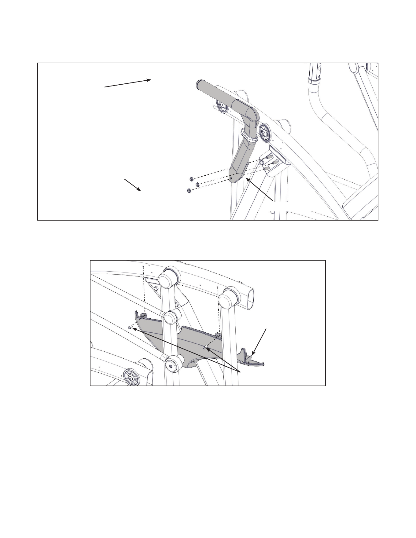
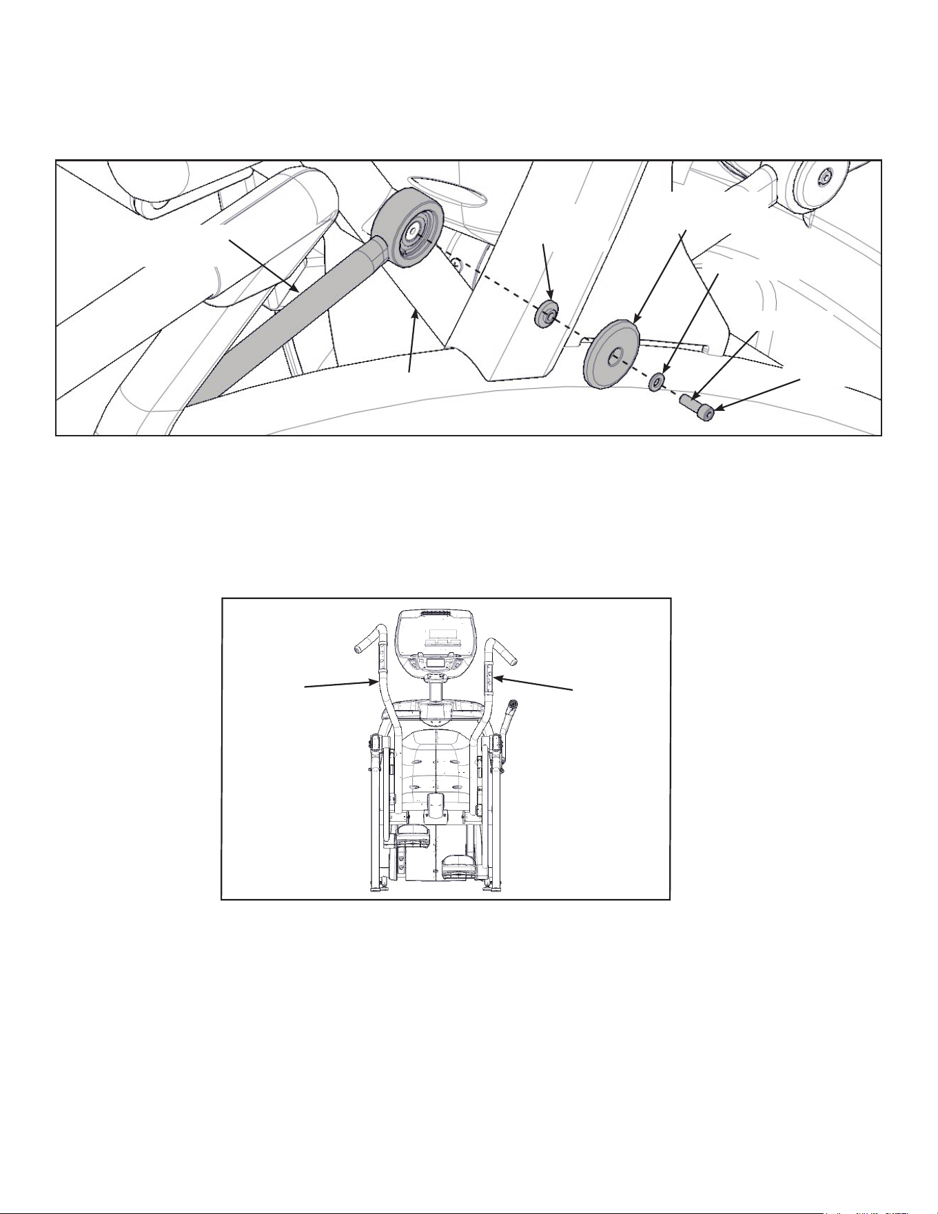
Remove left and right handle assembly
The left and right handle assemblies are shipped in rotated positions. The handle assemblies must be
removed and rotated 180 degrees for proper setup and assembly.
Shipping
Position
1. Remove a screw and washer from the left handle assembly using two 7/32” Allen wrenches.
Left
Handle
Washer
Pivot Pin Assembly
Screw
2. Slide pivot pin assembly out and remove left handle assembly.
3. Rotate left handle assembly 180 degrees.
4. Apply Loctite to threads inside the pivot pin and screw.
5. Place left handle assembly in position and slide pivot pin assembly back in place.
6. Install the screw and washer to the left handle assembly using two 7/32” Allen wrenches.
39
Cybex Owner’s Manual
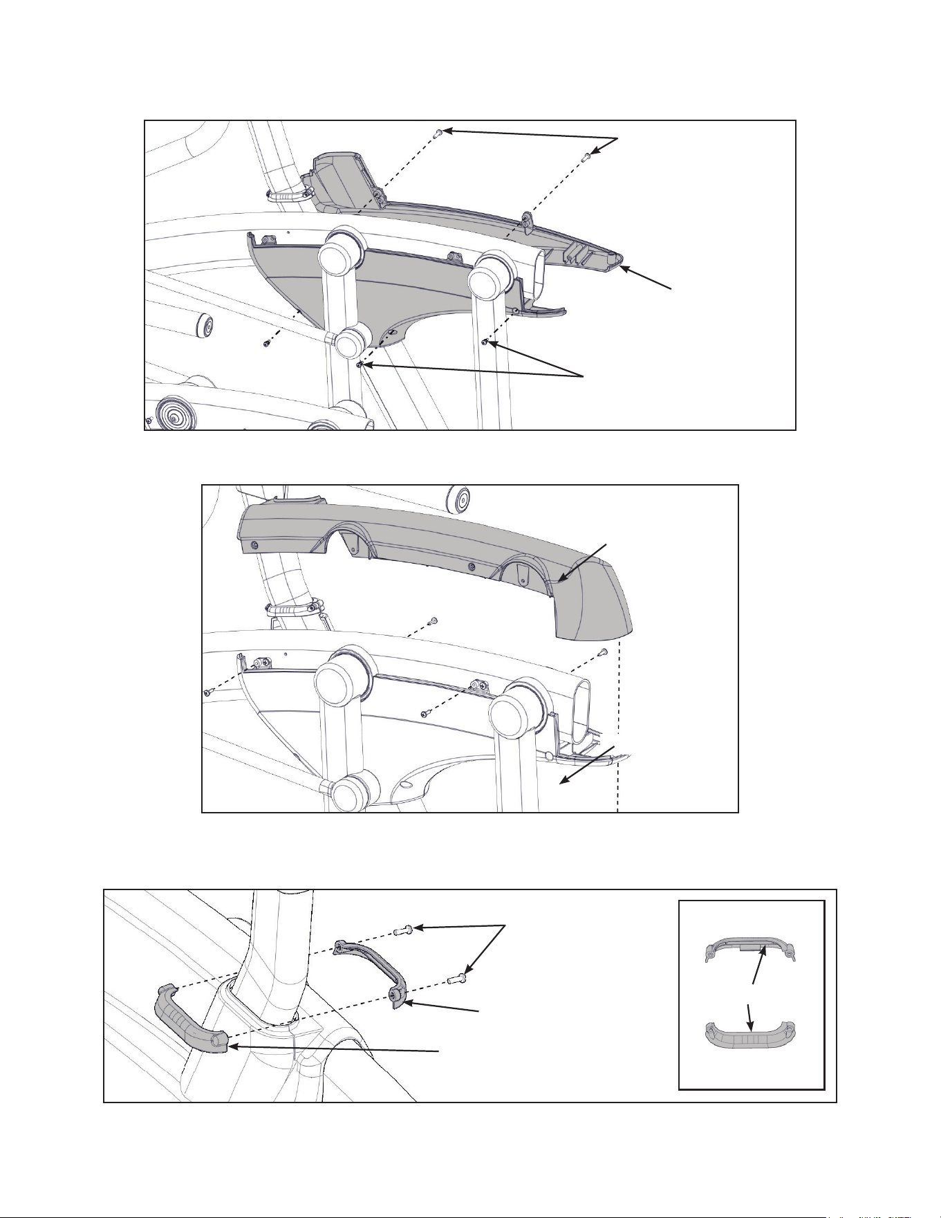
7. Remove a screw and washer from the right handle assembly using two 7/32” Allen wrenches.
Right
Handle
Washer
Screw
Pivot Pin Assembly
8. Slide pivot pin assembly out and remove right handle assembly.
9. Rotate right handle assembly 180 degrees.
10.Apply Loctite to threads inside the pivot pin and screw.
11.Place right handle assembly in position and slide pivot pin assembly back in place.
12.Install the screw and washer to the right handle assembly using two 7/32” Allen wrenches.
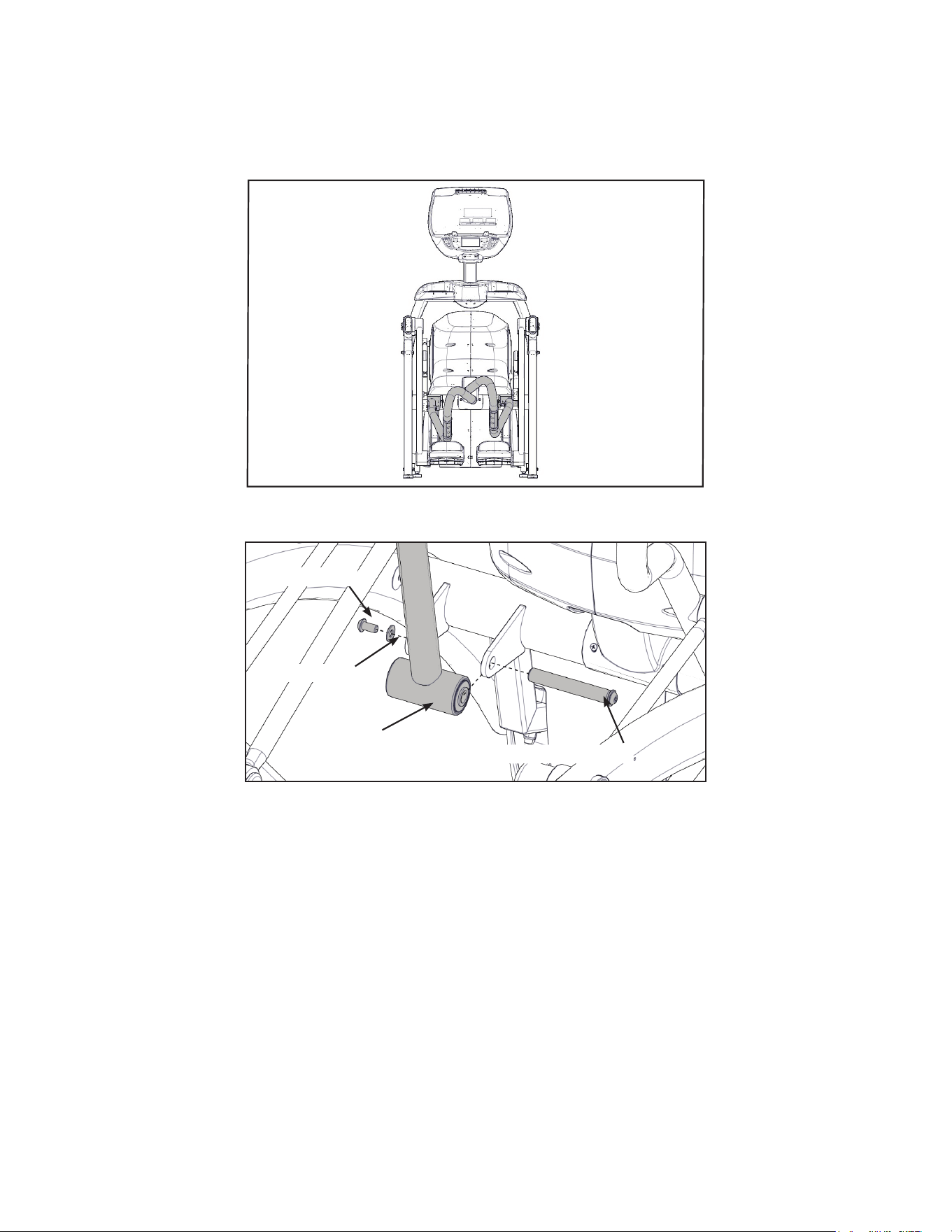
Install the left linkage rod
1. Pivot left handle assembly up and slide left linkage rod onto left arm.
Left Linkage
Rod
Linkage Rod
Cap
Screw
Washer
Left Arm
Flange
Spacer
Loctite
2. Place a drop of Loctite onto the screw.
3. Install the screw, washer, linkage rod cap, and flange spacer using a 3/16” Allen wrench.
4. Tighten screw to a minimum of 90 in/lbs.
40
Cybex Owner’s Manual
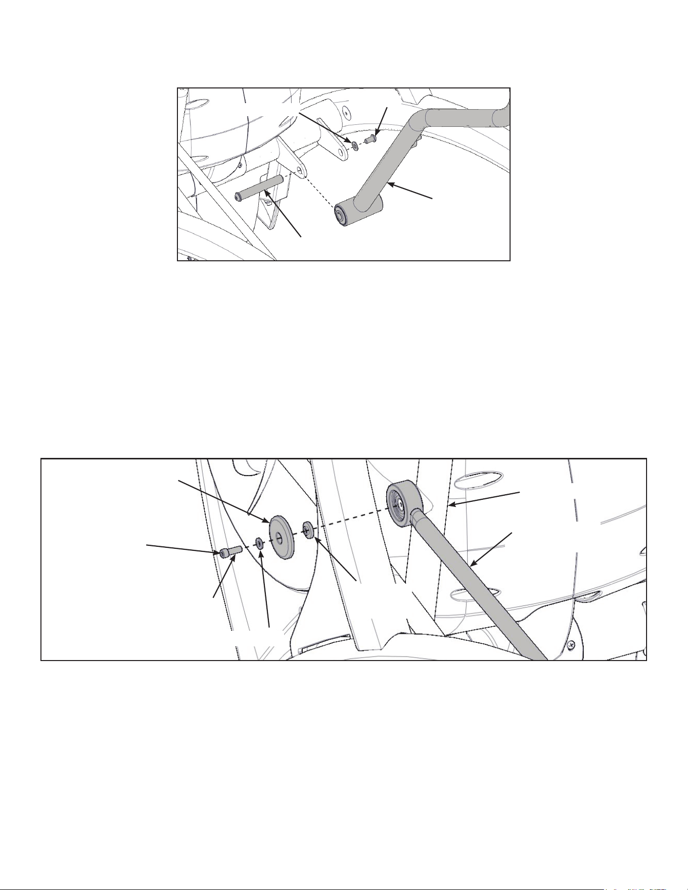
Install right linkage rod
1. Pivot right handle assembly up and slide right linkage rod onto right arm.
Right Linkage
Rod
Linkage Rod
Cap
Screw
Washer
Right Arm
Flange
Spacer
Loctite
2. Place a drop of Loctite onto the screw.
3. Install the screw, washer, linkage rod cap, and flange spacer using a 3/16” Allen wrench.
4. Tighten screw to a minimum of 90 in/lbs.
Verify handle assemblies are now installed in the correct position.
Correct
Position
Left
Handle
Assembly
Right
Handle
Assembly
41
Cybex Owner’s Manual
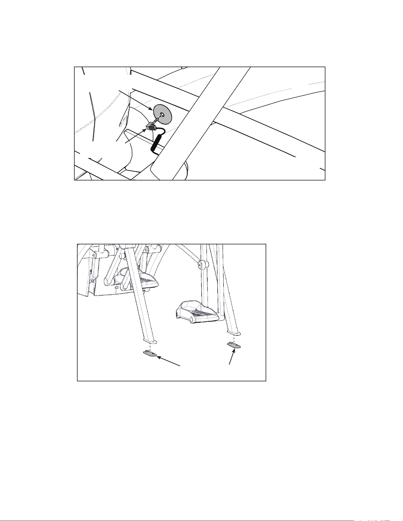
Connect contact heart rate cable
1. Plug right heart rate cable into main frame socket.
Heart Rate
Wire
Main Frame
Socket
Right Side
Shown
Position plug so handle does not
rubcableduringoperation.
2. Plug left heart rate cable into main frame socket.
Attach foot pads
Have one person lift the unit while a second person places a foot pad under each of the two back
feet.
Foot Pads (2)
42
Cybex Owner’s Manual
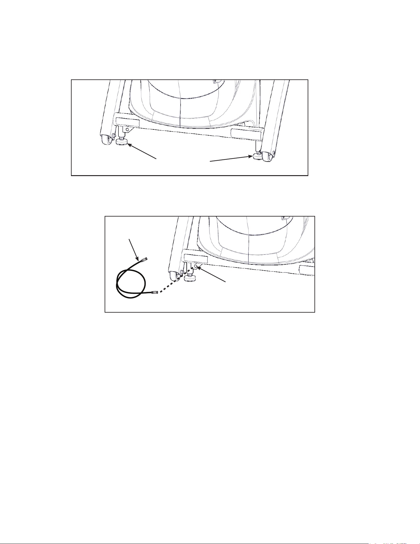
Level unit
Conrm unit is on a level surface. If not, use a 9/16” open-end wrench to adjust the leveling feet up or
down.
Leveling Feet
Install coax cable (E3 View Monitor option)
Install 6’ coax cable to the coax cable connector in base of unit.
6’ Coax
Cable
Coax Cable
Connector
Visually inspect unit
1. Carefully remove any package material from arms and rest of unit.
2. Carefully examine the unit to ensure assembly is correct and complete.
43
Cybex Owner’s Manual
Setup
Use the following instructions to setup the units settings.
1. Plug the optional power cord and E3 View Monitor power cord (E3 View Monitor units only)
into a power outlet from a grounded circuit, See Electrical Requirements. Coil up the
remainder of the power cord and place it out of the way. The control panel will light up and be
in the Dormant Mode.
2. Hold the handrails to steady self while stepping into the foot plates.
3. Begin striding. Verify lower heart rate cable is not rubbing on handle during operation.
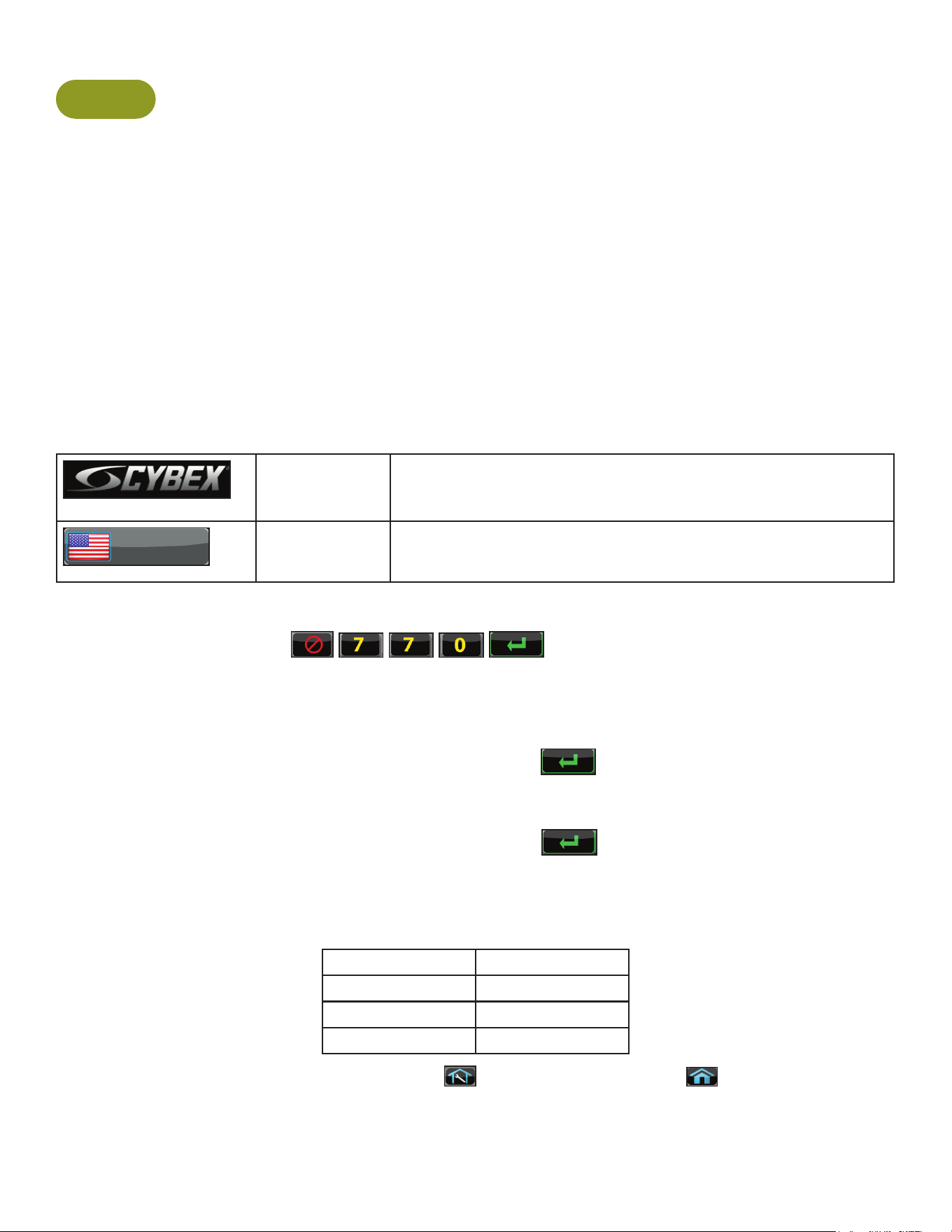
Initial setup
Perform this procedure during the installation of the unit. Once complete, refer to Setup Options
below.
CYBEX
LOGO
Press and hold Cybex logo for 6 seconds to access Screen
Lock and Toolbox. See Preventive Maintenance section.
ENGLISH
LANGUAGE
ICON
Press and hold language logo for 6 seconds to access
Screen Lock and Toolbox.
1. Press the Access Toolbox icon to display the Access to Toolbox login screen.
2. Enter the sequence:
.
3. Press the Setup icon to display the setup menu.
4. Tap the Time icon to advance to the Set the Time screen.
5. Adjust the time if needed, then tap the ENTER icon
.
6. Tap the Date icon to advance to the Set the Date screen.
7. Adjust the date if needed, then tap the ENTER icon
.
8. Tap the Units icon to select the Set units preference screen.
9. Select the unit preferences from the following options:
Distance Units Weight Units
Miles Lbs.
Km Kg
Stone
Exit Set Up Mode by tapping the Toolbox icon
, then tap the Home icon . The screen will
refresh.
44
Cybex Owner’s Manual
Setup options
Enter setup options.
CYBEX
LOGO
Press and hold Cybex logo for 6 seconds to access Screen
Lock and Toolbox. See Preventive Maintenance section.
ENGLISH
LANGUAGE
ICON
Press and hold language logo for 6 seconds to access
Screen Lock and Toolbox.
1. Press the Access Toolbox icon to display the Access to Toolbox login screen.
2. Enter the sequence:
.
3. Press the Setup icon to display the setup menu.
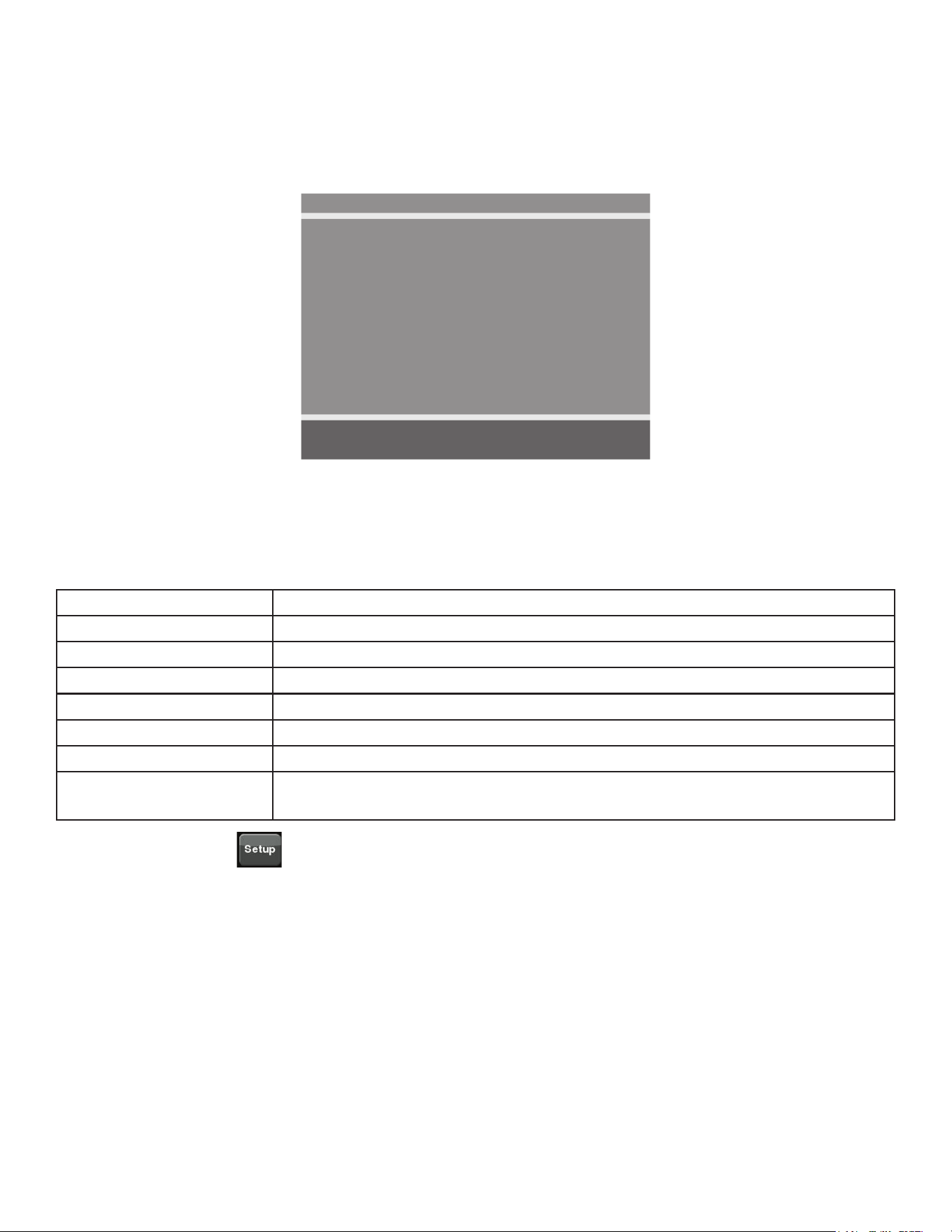
The Setup options are:
Time and Date See Initial setup above.
Units See Initial setup above.
A/V Device (not shown for
E3 View Monitor)
Select No TV or Wireless TV.
A/V Cong (not shown for
E3 View Monitor)
Active when A/V Device is set to Wireless TV. See A/V Cong and
FM Radio Presets below.
FM Radio Presets (not
shown for E3 View Monitor)
Active when A/V Device is set to Wireless TV. See A/V Cong and
FM Radio Presets below.
PEM Setup Active when A/V Device is set to Embedded TV. See
E3 View Monitor Controls and E3 View Monitor Setup below.
Workout times Set Default and Max workout times. Default choices are 20, 30, or
60 minutes. Max choices are 20, 30, 60, or OFF.
Pause Set Pause time. Choices are OFF, 0:30, 1:00, or 2:00 minutes.
Sound Select console beeper settings. Choices are ON, Some, or OFF.
Selecting Some enables beeper for safety related notications, such
as Entering Active, Exiting Active, and Cool Down.
Language Select language to use for CardioTouch text. Toolbox is only
available in English.
Restore Factory Defaults Restores all setup variables back to factory defaults. Does not affect
Time or Date.
Exit Set Up Mode
Exit Set Up Mode by tapping the Toolbox icon
, then tap the Home icon . The screen will
refresh.
45
Cybex Owner’s Manual
A/V Configuration and FM Radio Presets
Setting up the Cybex Wireless Audio Receiver Module for a 770A and 770AT requires four
steps:
• Determine the type of transmitter used (MYE 900MHz, Broadcast Vision 863MHz, etc. or TV FM).
• Set A/V Device to “Wireless TV”.
• Assign a TV channel number to each transmitter on the console.
• Add FM radio station presets (optional).
Accessories Required:
• Headphones (not included)
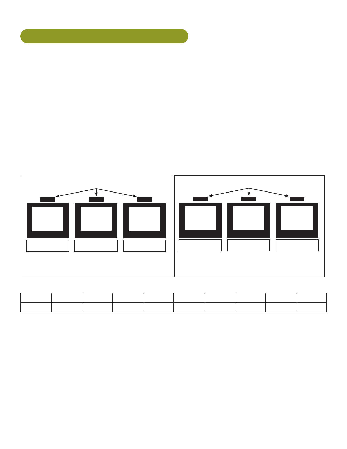
Determine transmitter type
There are two types of transmitters, UHF or TV FM. UHF transmitters will have TV’s identied by
number, example TV1. TV FM transmitters will have TV’s identied with FM frequencies,
example 93.1.
UHF Transmitters
Follow procedure:
Setup UHF Transmitters
TV1 TV2 TV3
Follow procedure:
Setup TV FM Transmitters
TV FM Transmitters
93.1 97.5 102.7
For TV FM transmitters, record FM frequencies for all TV’s:
1 2 3 4 5 6 7 8 9 10
A/V setup mode
1. Plug the optional power cord into a power outlet from a grounded circuit, See Electrical
Requirements. Coil up the remainder of the power cord and place it out of the way. The
control panel will light up and be in the Dormant Mode.
2. Hold the handrails to steady self while stepping into the foot plates.
3. Begin striding.
46
Cybex Owner’s Manual
CYBEX
LOGO
Press and hold Cybex logo for 6 seconds to access Screen
Lock and Toolbox. See Preventive Maintenance section.
ENGLISH
LANGUAGE
ICON
Press and hold language logo for 6 seconds to access
Screen Lock and Toolbox.
4. Tap Access Toolbox to access the Toolbox login screen.
5. Enter the sequence:
.
6. Tap Setup at the main Toolbox screen.
7. Tap Scroll Right
to navigate to the A/V Device icon.
8. Tap A/V Device.
9. Tap Device Installed to select “Wireless TV” if not set.
10.Tap Toolbox to return to the Toolbox screen.
11.Plug in headphones to listen for channels during setup.
Setup UHF Transmitters
For transmitter types 900 MHz, 863 MHz or 806 MHz. Use this procedure to associate channel
numbers to your TV transmitters. If using an FM transmitter system, skip to Setup TV FM
Transmitters.
Pick transmitter type
1. Tap Setup at the main Toolbox screen.
2. Tap Scroll Right
to navigate to the A/VCong icon.
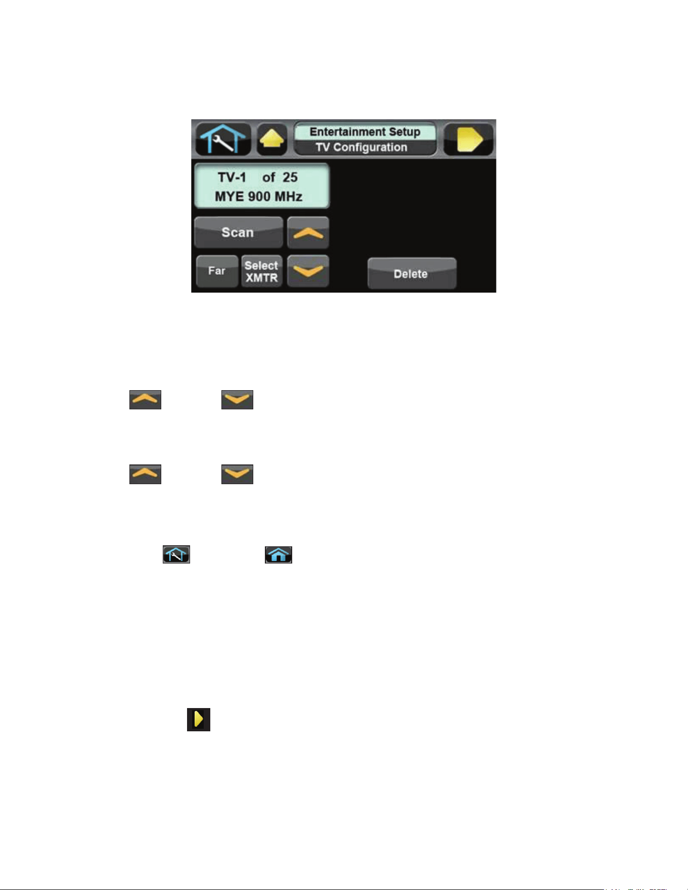
3. Tap A/VCong to enter “TV Conguration”.
4. The display box will show the transmitter type. If your transmitter is not shown, tap Select
Xmtr to toggle through the choices until your transmitter type is shown. If the display box is
blank, there may be a problem with the embedded receiver, contact Customer Service.
900 MHz System 863 MHz System 806 MHz System
“M 900” MYE “M 863” MYE “J1 806” Japan 14 channels
“C 900” Cardio Theater “E 863” Enercise “J2 806” Japan 30 channels
“E 900” Enercise “A 863” Audeon
“B 900” Broadcast Vision
47
Cybex Owner’s Manual
5. Press Scan to scan for available channels. The scan can take up to 10 seconds and then
display “TV-1 of #”. The “#” symbol is total number of strong UHF channels found. Some of
these channels may not be signals from the TV transmitters and need to be deleted.
If no TV numbers appear, no UHF transmitters were discovered. Verify the UHF transmitters are
powered on and set to their respective TV numbers (1,2,3, etc.) or toggle the Near/Far setting and re-
scan.
Review channels
1. Tap Up or Down to listen to available channels with the headphones.
2. Delete unwanted channels by pressing Delete to delete channel. Repeat process for additional
unwanted channels.
3. Tap Up or Down to scroll through and verify all TV channels. If all TV transmitters
are stored, and they all correlate the TV number to the correct TV heard, setup is complete. If
all channels did not show up in the scan as expected, toggle the Near/Far setting and re-scan
the transmitter codes (see documentation for your transmitters to perform a code change.)
4. Tap Toolbox then Home to exit setup. Transmitter setup complete.
5. Press Show All to conrm the TV numbers correspond to the frequencies entered.
6. Proceed to Add FM Radio Stations (optional).
Setup TV FM Transmitters
If your TV’s use FM transmitters, follow these instructions to assign a TV channel to each frequency.
1. Tap Setup at the main Toolbox screen.
2. Tap Scroll Right
to navigate to the A/VCong icon.
3. Tap A/VCong to enter TVConguration.
4. Tap Select Xmtr to select your transmitter type as “TV FM”.
48
Cybex Owner’s Manual
Enter TV channels using one of the following procedures
• Tap Seek to seek the next TV FM frequency or Up or Down to tune manually. Press
Add to store channel.
• Tap the keypad numbers to enter known channel, Press Enter and Add to store channel.
5. Repeat procedure to add all TV FM channels.
6. Press Toolbox then Home to exit setup when all the TV’s FM transmitter
frequencies have a TV number. Transmitter setup complete.
7. Proceed to Add FM Radio Stations (optional).
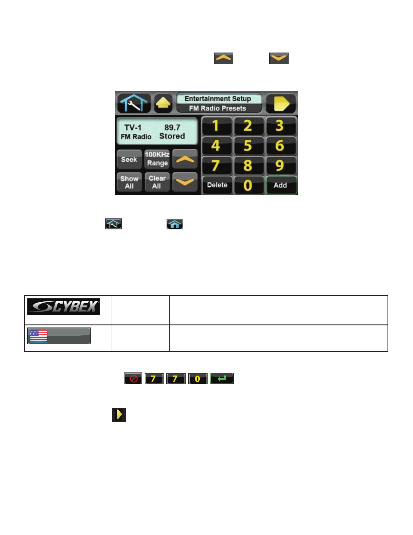
Add FM Radio Stations (optional)
If strong local FM Radio Stations are available in the area, you can set those as presets.
CYBEX
LOGO
Press and hold Cybex logo for 6 seconds to access Screen
Lock and Toolbox. See Preventive Maintenance section.
ENGLISH
LANGUAGE
ICON
Press and hold language logo for 6 seconds to access
Screen Lock and Toolbox.
1. Tap Access Toolbox to access the Toolbox login screen.
2. Enter the sequence:
.
3. Tap Setup at the main Toolbox screen.
4. Tap Scroll Right
to navigate to the FM Radio Presets icon.
5. Tap FM Radio Presets to display FM Radio Presets on the console.
49
Cybex Owner’s Manual
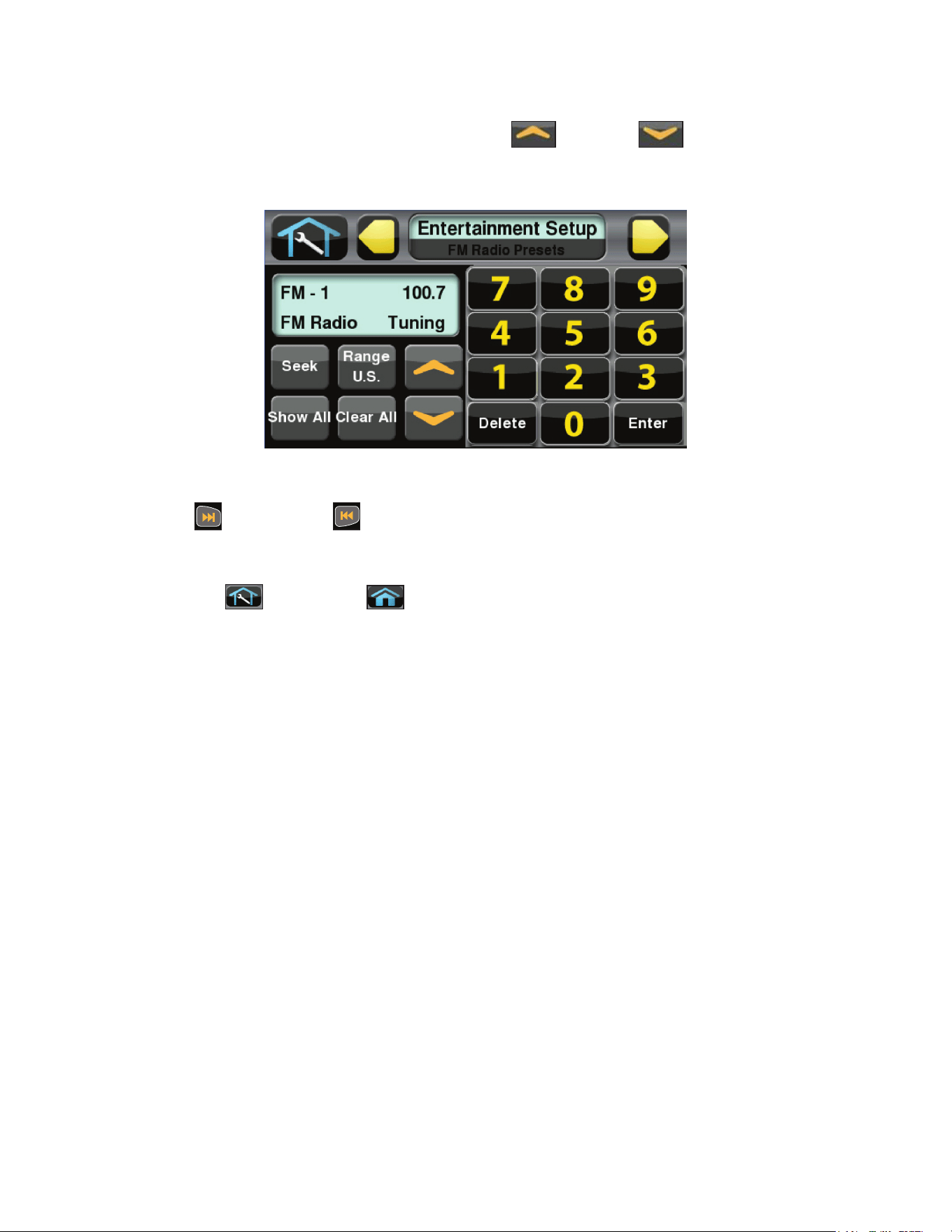
Enter FM radio channels using one of the following procedures
• Tap Seek to seek the next FM radio frequency or Up or Down to tune manually. Tap
Add to store channel.
• Tap the keypad numbers to enter known channel, Press Enter and Add to store channel.
1. Repeat procedure to save up to 32 FM radio stations.
2. Tap Next or Previous to scroll through and verify all FM radio stations.
3. Press Show All to to conrm the radio station numbers correspond to the frequencies entered.
4. Tap Toolbox then Home to exit setup when all FM radio stations are stored.
50
Cybex Owner’s Manual
Adjust sound volumes
After completing the channel setup, it may be necessary to adjust the volume level of each TV so they
all have similar volume levels. Since the FM Radio station volume can not be adjusted, this will be
used as a ‘base line’ volume to adjust the TV’s to.
1. Plug headphones into headphone jack.
2. Begin striding and press the QUICK START icon.
3. Press the TV icon.
4. Tap Next or Previous to select an FM radio station. This volume is not adjustable and
is the base volume.
5. Tap Up or Down to select a TV station.
6. Adjust the volume of each TV to match an FM Radio Station or each other using the TV’s
remote control. The goal is for a volume setting of 10 on the unit to be the same for all TV and
FM channels.
7. Repeat procedure for all TV’s.
Using the Cybex Wireless Audio Receiver
1. Plug headphones into headphone jack.
2. Begin striding and press the QUICK START icon.
3. Tap the TV icon to listen to TV channels. Press the FM icon to listen to FM radio channels.
4. Tap Next or Previous to change TV or FM channels.
5. Tap volume Up or Down to adjust volume.
51
Cybex Owner’s Manual
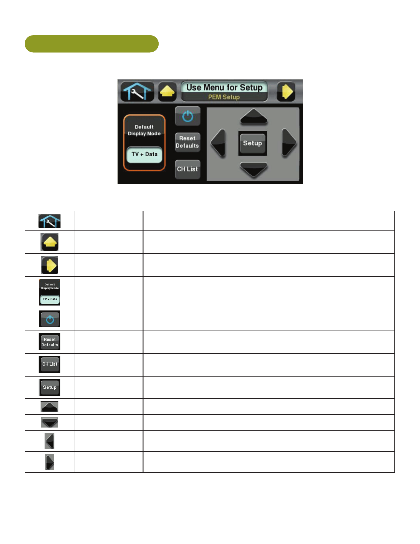
E3 View Monitor Controls
The CardioTouch screen is used to perform all setup operations for the E3 View Monitor.
CardioTouch screen functions
Wrench Icon Return to Toolbox home
Up Go to Setup home screen
Next Moves forward in Setup menu to next screen
Default Display
Mode
Select TV + Data, TV Only or Data Only
On/Off Turn the E3 View Monitor on or off
Reset Defaults Reset the setup values and clear all programmed channels.
CH List List all available channels
Setup Toggles the setup menu
Navigate up Navigate up through the on-screen menu
Navigate down Navigate down through the on-screen menu
Navigate left Decrease value
Navigate right Increase value
52
Cybex Owner’s Manual
E3 View Monitor Setup
Access Setup Screen
CYBEX
LOGO
Press and hold Cybex logo for 6 seconds to access Screen
Lock and Toolbox. See Preventive Maintenance section.
ENGLISH
LANGUAGE
ICON
Press and hold language logo for 6 seconds to access
Screen Lock and Toolbox.
1. Tap the Access Toolbox icon to display the Access to Toolbox login screen.
2. Enter the sequence:
.
3. Tap the Setup icon to display the setup menu.
4. Tap the Shift Right icon to navigate to the EPEM Setup icon.
5. Tap the EPEM Setup icon.
6. Tap the Setup
icon to advance to the SETUP MODE screen on the E3 View Monitor.
Follow procedure to setup the E3 View Monitor.
SETUP MODE
■ Picture ►
■ Channels ►
■ Features ►
■ OSD Language English
Position: ▲ ▼
Exit: SETUP Next: ◄ ►
53
Cybex Owner’s Manual
Picture
1. Tap ▲ or ▼ to select Picture.
2. Tap ► to select access Picture menu.
Picture
■ Brightness 65
■ Contrast 70
■ Color 75
■ Tint 0
■ Color Temperature ►
■ Sharpness 60
■ Noise Reduction Enabled
■ HDMI Picture ►
Position: ▲ ▼
Exit: SETUP Next: ◄ ►
3. Tap ▲ or ▼ to select settings.
4. Tap ◄ or ► to adjust settings.
Picture settings
Brightness Adjust range from 1 to 100. Default is 65.
Contrast Adjust range from 1 to 100. Default is 70.
Color Adjust range from 1 to 100. Default is 75.
Tint Adjust range from 1 to 100. Range is R50 to G50. Default is 0.
Color Temperature Adjust color balance of Red, Green and Blue temperatures.
Sharpness Adjust range from 1 to 100. Default is 60.
Noise Reduction Select Enabled (Default) or Disabled.
HDMI Picture Set to Auto or Adjust settings as needed. Available only when HDMI
signal is present.
5. Tap the Setup
icon to return to SETUP MODE menu.
54
Cybex Owner’s Manual
Channels
1. Tap ▲ or ▼ to select Channels.
2. Tap ► to select access Channels menu.
ATSC Monitor
Channels
■ Signal Cable STD
■ Auto Program ►
■ Add/Delete Channels ►
■ Parental Control ►
■ Default Channel Last
■ Channel Lock Disabled
■ Channel Memory Override Enabled
Position: ▲ ▼
Exit: SETUP Next: ◄ ►
DVB-T Monitor
Channels
■ Auto Program ►
■ Manual Program ►
■ Add/Delete Channels ►
■ Parental Control ►
■ Default Channel Last
■ Channel Lock Disabled
■ Channel Memory Override Enabled
Position: ▲ ▼
Exit: SETUP Next: ◄ ►
3. Tap ▲ or ▼ to select settings.
4. Tap ◄ or ► to adjust settings.
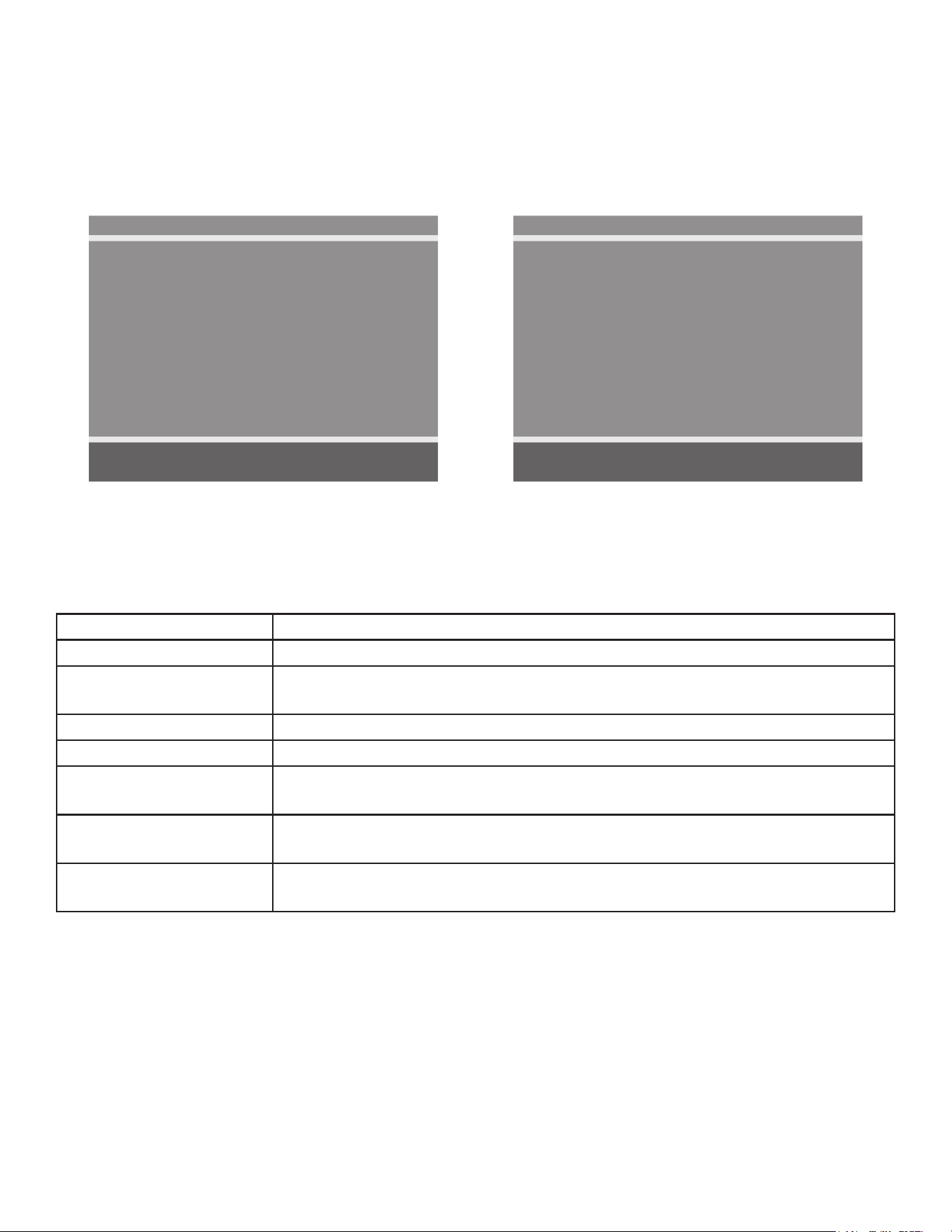
Channel settings
Signal (ATSC only) Select Air, Cable STD, Cable IRC, or Cable HRC.
Auto Program See Below
Manual Program
(DVB-T only)
See Below
Add/Delete Channels See Below
Parental Control Block channels based on TV ratings.
Default Channel Select channel to display on power up. Select from available channels or
last.
Channel Lock Select Enabled or Disabled. If enabled only one channel is shown, user
cannot change channels.
Channel Memory
Override
Select Enabled or Disabled. If enabled allows user to select any available
channel.

55
Cybex Owner’s Manual
Auto Program (ATSC Monitor)
1. Tap ▼ to select Auto Program.
2. Tap ► to enter the menu.
3. Tap ▲ or ▼ to select Mode.
ATSC Monitor
Auto Program
■ Mode Analog Only
■ Channel Sequence Interleave A + D
■ Additional Digital Signal None
■ Channel Map Programmed ►
Position: ▲ ▼
Exit: SETUP Next: ◄ ►
4. Tap ◄ or ► to set the scope of channel scanning.
• Analog Only (Default): TV searches for analog channels only.
• Digital Only: TV searches for digital channels only.
• Analog and Digital: TV searches for both analog and digital channels.
5. Tap ▼ to select Channel Sequence.
6. Tap ◄ or ► to set the Channel Sequence in which the channels are displayed after searching.
• Interleave A+D: In the order of channel number regardless of the system.
• All A then D: Digital channels are displayed after all analog channels.
7. Tap ▲ or ▼ to select Additional Digital Signal. Not available when Mode is set to Analog
Only.
8. Tap ◄ or ► to choose the Additional Digital Signal source. Choices are: None, Air, Cable
STD, Cable IRC, or Cable HRC.
9. Tap ▼ to select Channel Map.
10.Tap ► to start auto programming. A conrmation menu will appear before proceeding.
11.Tap ▲(Yes) to start auto programming. Tap ▼(No) button to cancel the operation. The TV
will now search all available channels with an on-screen progress percentage displayed.
Any tuning Mode that includes Digital channels will require several minutes to complete auto
programming.
This may take 20 or more minutes. If screen shuts off, tap the
icon to turn monitor on.
12.Tap the Setup
icon to return to normal TV viewing once auto programming is complete.

56
Cybex Owner’s Manual
13.Tap the icon to list programmed channels.
14.Tap the Setup
icon to return to SETUP MODE menu.
Auto Program (DVB-T Monitor)
1. Tap ▼ to select Auto Program.
2. Tap ► to enter the menu.
3. Tap ▲ or ▼ to select Country.
DVB-T Monitor
Auto Program
■ Country ---
■ Mode Analog Only
■ Channel Map Blank ►
Position: ▲ ▼
Exit: SETUP Next: ◄ ►
Available countries are:
Albania, Austria, Australia, Belgium, Bosnia, Bulgaria, China, Croatia, Czech, Denmark, Estonia,
Finland, France, Germany, Greece, Hungary, Ireland, Italy, Kazakhstan, Latvia, Lithuania,
Luxembourg, Moroco, Netherlands, Norway, Poland, Portugal, Romania, Russia, Serbia, Slovakia,
Slovenia, Spain, Sweden, Switzerland, Turkey, Uk, and Ukraine.
4. Tap ▲ or ▼ to select Mode.
5. Tap ◄ or ► to set the scope of channel scanning.
• Analog Only (Default): TV searches for analog channels only.
• Digital Only: TV searches for digital channels only.
• Analog and Digital: TV searches for both analog and digital channels.
6. Tap ▼ to select Channel Map.
7. Tap ► to start auto programming. A conrmation menu will appear before proceeding.
8. Tap ▲(Yes) to start auto programming. Tap ▼(No) button to cancel the operation. The TV
will now search all available channels with an on-screen progress percentage displayed.
Any tuning Mode that includes Digital channels will require several minutes to complete auto
programming.
This may take 20 or more minutes. If screen shuts off, tap the
icon to turn monitor on.
57
Cybex Owner’s Manual
9. Tap the Setup icon to return to normal TV viewing once auto programming is complete.
10.Tap the
icon to list programmed channels.
11.Tap the Setup
icon to return to SETUP MODE menu.
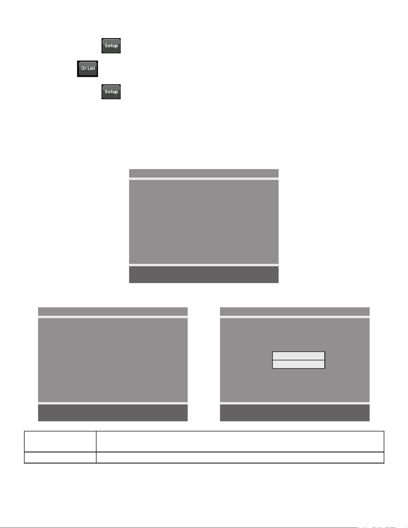
Manual Program (ATSC and DVB-T)
1. Tap ▼ to select Manual Program.
2. Tap ► to enter the menu.
3. Tap ▲ or ▼ to select Mode.
Manual Program
■ Mode ATV
■ Conrmation ►
Position: ▲ ▼
Exit: SETUP Next: ◄ ►
4. Tap ◄ or ► to select ATV or DTV.
ATV Manual Program
■ Storage 1
■ System BG
■ Band V/UHF
■ Channel 1
■ Name C 01
■ Search ◄ ►
■ Save ►
Position: ▲ ▼
Exit: SETUP Next: ◄ ►
DTV Manual Program
■ UHF CH. ►
■ Save 21
Bad Nor. Good
Signal Strength
Signal Quality
Position: ▲ ▼
Exit: SETUP Next: ◄ ►
ATV Mode Adjust settings for Storage, System, Band, Channel, Name, or Search. Select
Save to save settings.
DTV Mode Select UHF channel. Select Save to save settings.
58
Cybex Owner’s Manual
Add/Delete Channels (ATSC and DVB-T)
1. Tap ▼ to select Add/Delete Channels.
2. Tap ► to enter the Add/Delete Channels menu.
Add/Delete Channels
■ Analog Channel 2
■ Add/Delete Analog Channel Added
■ Enable/Disable Digital Channel ►
Position: ▲ ▼
Exit: SETUP Next: ◄ ►
To add or delete an analog channel perform the following procedure. To enable or disable digital
channels, go to step 7.
3. Tap ◄ or ► to select the desired analog channel.
4. Tap ▲ or ▼ to highlight Add/Delete Analog Channel.
5. Tap ◄ or ► to select Added or Deleted.
6. Tap the Setup
icon to return to the previous menu. To exit, Tap the Setup icon
until the programming menus disappear. If there are more analog channels to be added or
deleted, repeat steps 3 through 5.
7. Tap ▲ or ▼ to highlight Enable/Disable Digital Channel.
8. Tap ► to select Enable/Disable Digital Channel. If there are not any channels programmed
in the Service Level, “No Channels Present” will appear in the menu.
9. Tap ▲ or ▼ to highlight the digital channel that needs to be enabled or disabled.
10.Tap ◄ or ► to select Enable or Disable.
11.Tap the Setup
icon to return to the previous menu.
Features
1. Tap ▲ or ▼ to select Features.
59
Cybex Owner’s Manual
2. Tap ► to select access Features menu.
ATSC Monitor
Features
■ Power on Captions Mode Last
■ Digital Mode Time Setup ►
■ Diagnostics ►
■ Caption Text Modes Disabled
Position: ▲ ▼
Exit: SETUP Next: ◄ ►
DVB-T Monitor
Features
■ Power on Subtitles Mode Last
■ Digital Mode Time Setup ►
■ Diagnostics ►
Position: ▲ ▼
Exit: SETUP Next: ◄ ►
3. Tap ▲ or ▼ to select settings.
4. Tap ◄ or ► to adjust settings.
Feature settings
Power on Captions Mode
(ATSC only)
Select Off or Last. Last will set caption mode to last used setting.
Power on Subtitles Mode
(DVB-T only)
Select Off or Last. Last will set subtitle mode to last used setting.
Digital Mode Time Setup Set current time automatically from digital signal. Select time zone
and daylight savings time to Auto, On, or Off.
Diagnostics Provides diagnostic information only. Settings cannot be changed.
Caption Text Modes (ATSC
only)
Select Enabled or Disabled.
5. Tap the Setup
icon to return to SETUP MODE menu.
OSD Language
1. Tap ▲ or ▼ to select OSD Language.
2. Tap ◄ or ► to select language.
ATSC choices English, Français or Español.
DVB-T choices English, Français, Español, Dutch, Danish, Russian, German, and Swedish.
4. Tap the Setup
icon to return to SETUP MODE menu.
Exit Set Up Mode by tapping the Toolbox icon
, then tap the Home icon . The screen will
refresh.
Setup Complete

60
Cybex Owner’s Manual
Testing Operation
Use the following instructions to test the full resistance and incline range of the unit:
1. Plug the optional power cord into a power outlet from a grounded circuit, See Electrical
Requirements. Coil up the remainder of the power cord and place it out of the way. If you do
not have the optional power supply, skip to step 3.
2. Verify the control panel will illuminate and is in Dormant Mode.
3. Hold the handrails to steady self while stepping into the foot plates.
4. Begin striding.
5. Verify lower heart rate cable is not rubbing on handle during operation.
6. Tap QUICK START icon on the CardioTouch screen.
7. Run unit through full resistance range. First press the RESISTANCE + key until unit reaches
its highest load (the display will show “100”). Then press the RESISTANCE - key until unit
reaches its lowest load (the display will show “0”).
When unit reaches the set incline and resistance, the displays will stop ashing and remain steadily
illuminated to indicate the desired settings have been reached.
8. Run unit through full incline range. First press the INCLINE key until the unit reaches its
highest incline (the display will show “20”). Then press the INCLINE key until unit reaches its
lowest incline (the display will show “0”).
WARNING: Serious injury or death can occur. To avoid injury or death the following
procedure must be followed. Wait until all moving parts come to a complete
stop before dismounting. Failure to wait for complete stop can trip or injure
user.
9. Press STOP twice to bring the incline back to its start position, end the workout review, and
return the display to Dormant Mode.
10.Wait until foot plates come to a complete stop before dismounting unit. Hold handrails to
steady self while stepping off unit.

61
Cybex Owner’s Manual
Operation
Intended Use
The intended commercial use of this machine is to aid exercise and improve general physical tness.
Terms Used
Active Mode – Any time the unit is controlling resistance and accumulating workout data. Active
Mode begins after tapping QUICK START icon during the initial count-down screen,
after completing the setup for a workout, or by default if the initial count-down screen
times out and enters Quick Start mode.
Auto-Scan – Display automatically cycles through workout data.
CardioTouch Screen – The CardioTouch Screen is the touch screen located in the handset area.
Cool Down – A reduction of work load for a short duration allows user to gently reduce heart rate.
Cool Down occurs two minutes prior to completion of the workout session.
Dormant Mode – Occurs when unit is plugged in with optional AC adapter and not in use.
Muscle Map – An anatomical representation of the human body with primary muscle groups lit by
multi-color LED’s. The color of the LED displays which muscle groups are targeted
and the relative intensity of the exercise.
Pause Mode – Occurs only if the Pause feature is enabled and user selects the STOP key from
Active Mode.
Workout Group – This begins after tapping the WORKOUTS icon. Select from available workouts.
Quick Start – Tap the QUICK START icon to enter into Quick Start Mode, where the user controls
the Incline and Resistance as time counts up. Also occurs after 40 seconds of the user
striding and not interacting with the console.
Workout Review – Review of the accumulated workout data will happen at the end of each workout
session.
Read and understand all warnings and cautions in the Safety Section and all operation
instructions in this chapter before operating unit.
62
Cybex Owner’s Manual
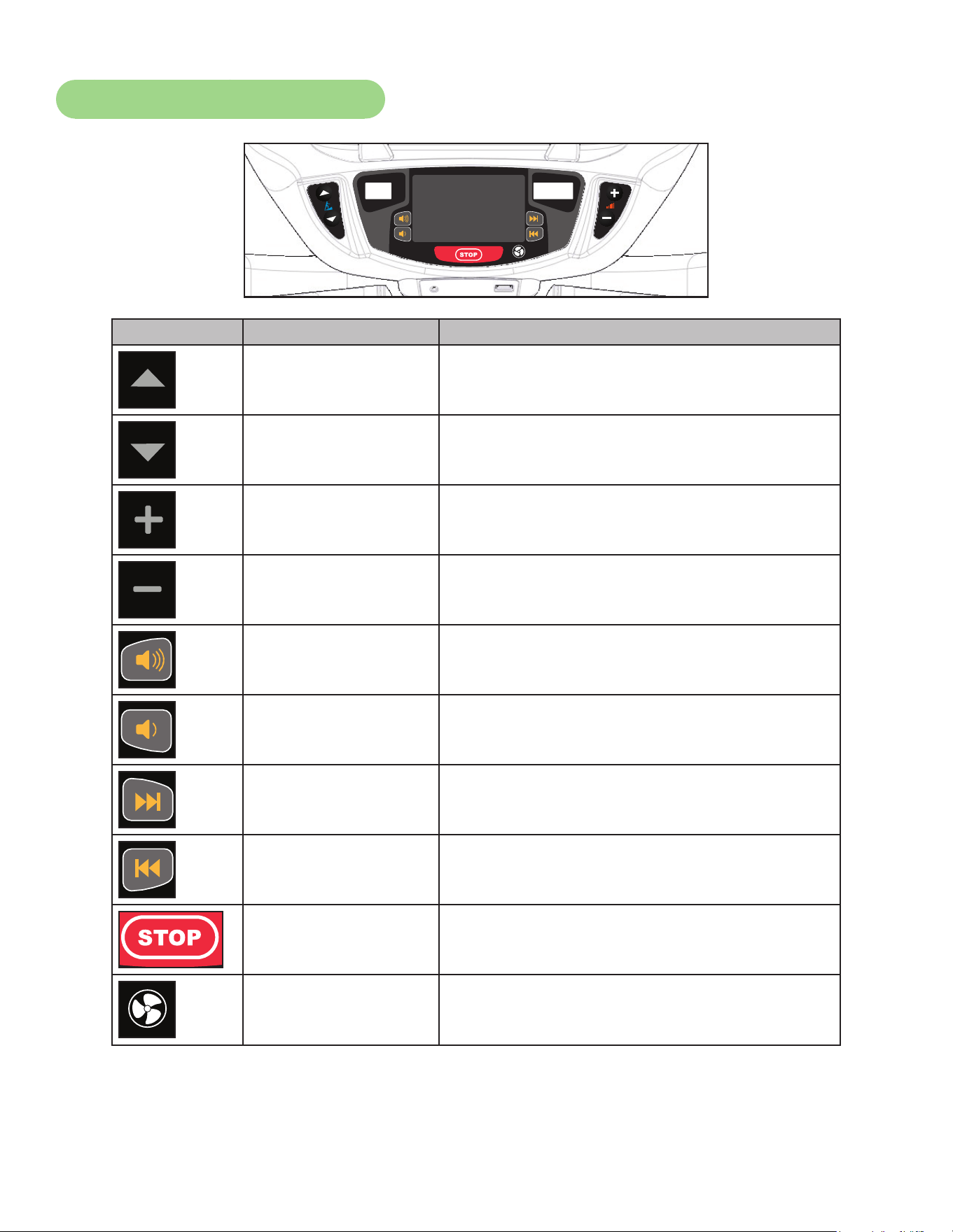
User Control Symbols Used
Control Control Name Description
INCLINE UP Adjust Incline up.
INCLINE DOWN Adjust Incline down.
RESISTANCE UP Adjust Resistance up.
RESISTANCE DOWN Adjust Resistance down.
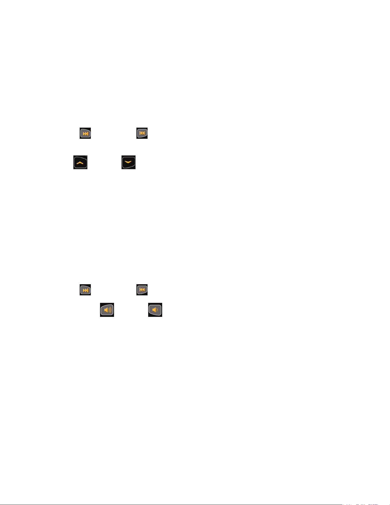
VOLUME UP Adjust Volume up.
VOLUME DOWN Adjust Volume down.
CHANNEL/TRACK
CONTROL
iPod - NEXT track.
A/V - Channel U P.
CHANNEL/TRACK
CONTROL
iPod - PREVIOUS track.
A/V - Channel DOWN.
STOP
If pause feature is enabled, press STOP once
to enter pause mode.
FAN
Default speed is OFF during active mode.
Press the FAN key to control fan speed.
Choices are OFF, LOW and HI.
63
Cybex Owner’s Manual
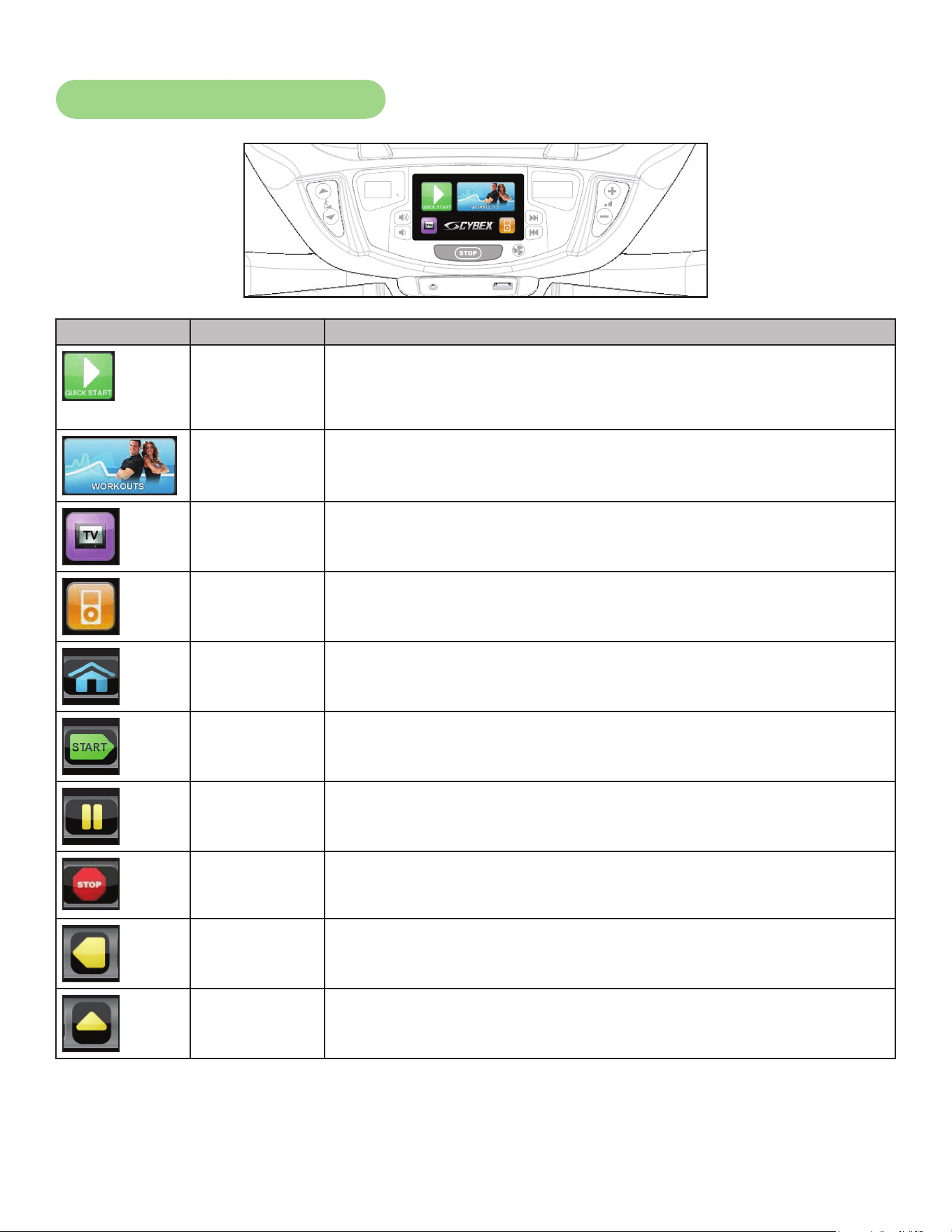
CardioTouch Symbols Used
Icon Icon Name Description
QUICK
START
Quick Start enters Active Mode at the default incline and resistance
with time counting up from 0:00.
WORKOUTS Tap Workouts icon to enter workout group selection.
TV Tap TV icon to enter TV control menu. If TV is not connected, icon
will be grayed out.
iPOD Tap iPod icon to enter iPod control menu. If iPod is not connected,
icon will be grayed out.
HOME Return to opening screen.
START
Enter Active Mode.
PAUSE
If pause feature is enabled, pause icon is shown. Press pause icon
or STOP button once to enter pause mode.
STOP
If pause feature is disabled, stop icon is shown. Press stop icon or
STOP button once to enter “Workout review”.
BACK
Return to previous or opening screen.
UP LEVEL
Go up one level or return to iPod screen.
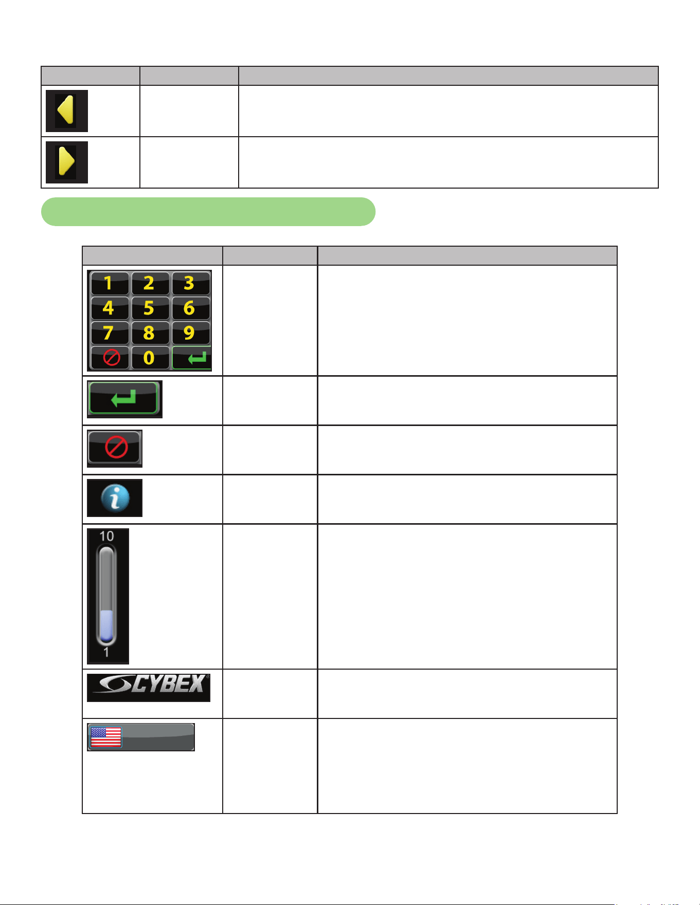
64
Cybex Owner’s Manual
Icon Icon Name Description
SHIFT LEFT Shift the screen left to view more options.
SHIFT RIGHT Shift the screen right to view more options.
CardioTouch Symbols Used (continued)
Icon Icon Name Description
KEYPAD Numeric keypad for entering data.
ENTER Select after entering information to enter value.
CLEAR Clear any values selected.
INFO Select to provide more information and details.
SCALE Displays current value and high/low range.
CYBEX
LOGO
Tap Cybex logo to access Screen Lock and
Toolbox. See Preventive Maintenance section.
ENGLISH
LANGUAGE
ICON
Tap language icon to select available
languages. Set languages available in Setup
Options section.
Press and hold language logo for 6 seconds to
access Screen Lock and Toolbox.
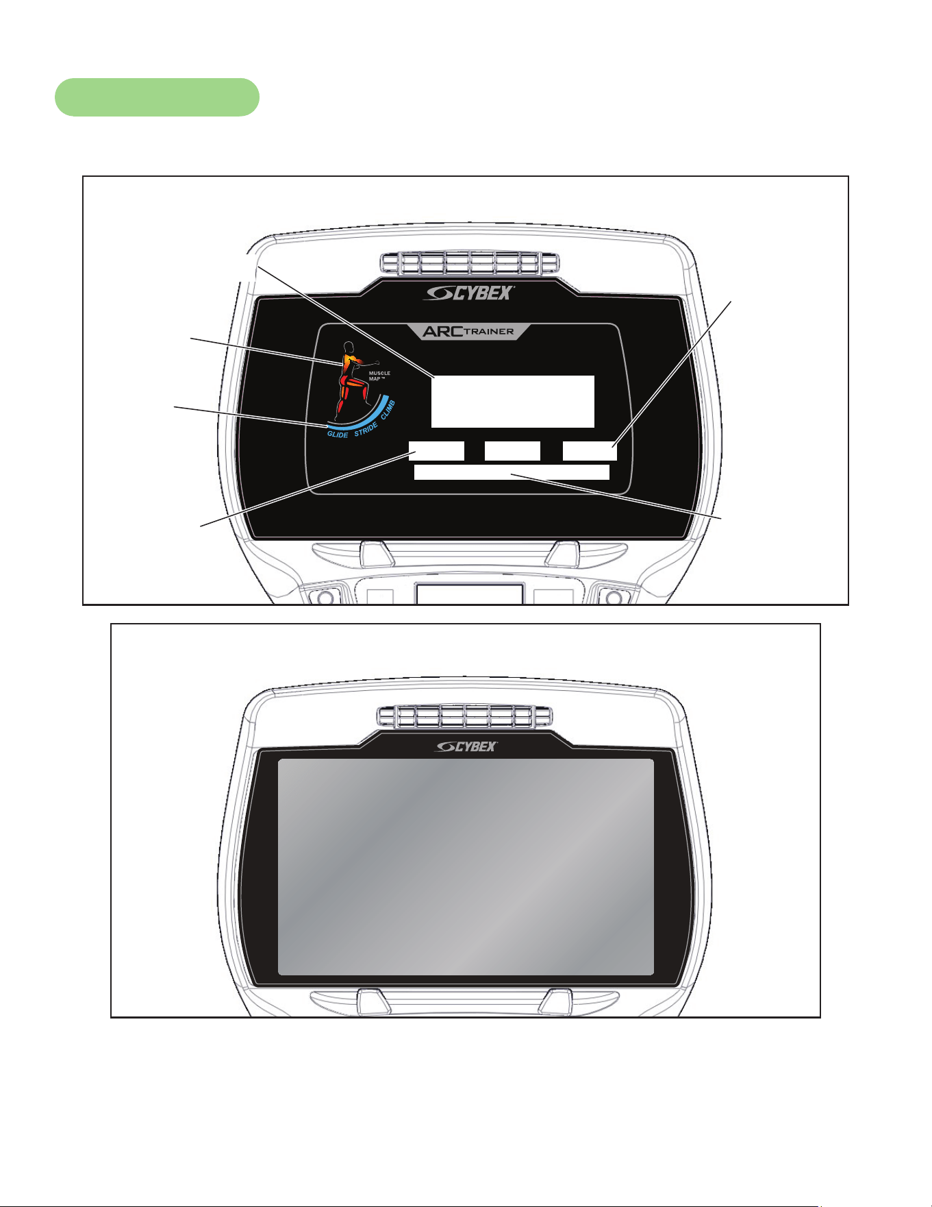
65
Cybex Owner’s Manual
Console Display
The 770A and 770AT models have two display options, LED or E3 View Monitor shown below.
®
Bar Graph
Data
Readouts
Muscle
Map
Incline
Meter
Enunciator
Heart Rate
Indicator
LED Display
E3 View Monitor Display
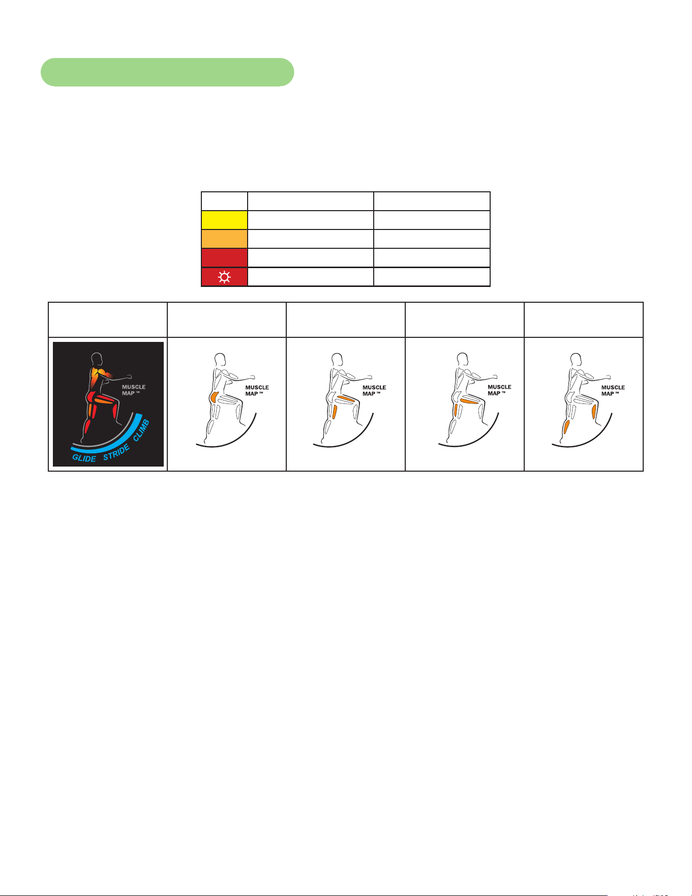
66
Cybex Owner’s Manual
Muscle Map and Incline Meter
Muscle Map – An anatomical representation of the human body with primary muscle groups lit by
multi-color LED’s. The color of the LED displays which muscle groups are targeted
and the relative intensity of the exercise.
The LED colors display intensity level.
LED Color Level
Yellow Low
Amber Medium
Red High
☼ Blinking Red Very high
Muscle Map and
Incline Meter
Glute Muscle Quadricep
Muscle
Hamstring
Muscle
Calf Muscle
Glute Quad
Hamstring Calf
Glute Quad
Hamstring Calf
Glute Quad
Hamstring Calf
Glute Quad
Hamstring Calf
Glute Quad
Hamstring Calf
Incline Meter – An LED meter displaying the incline setting. The meter increase or decreases as the
incline changes.
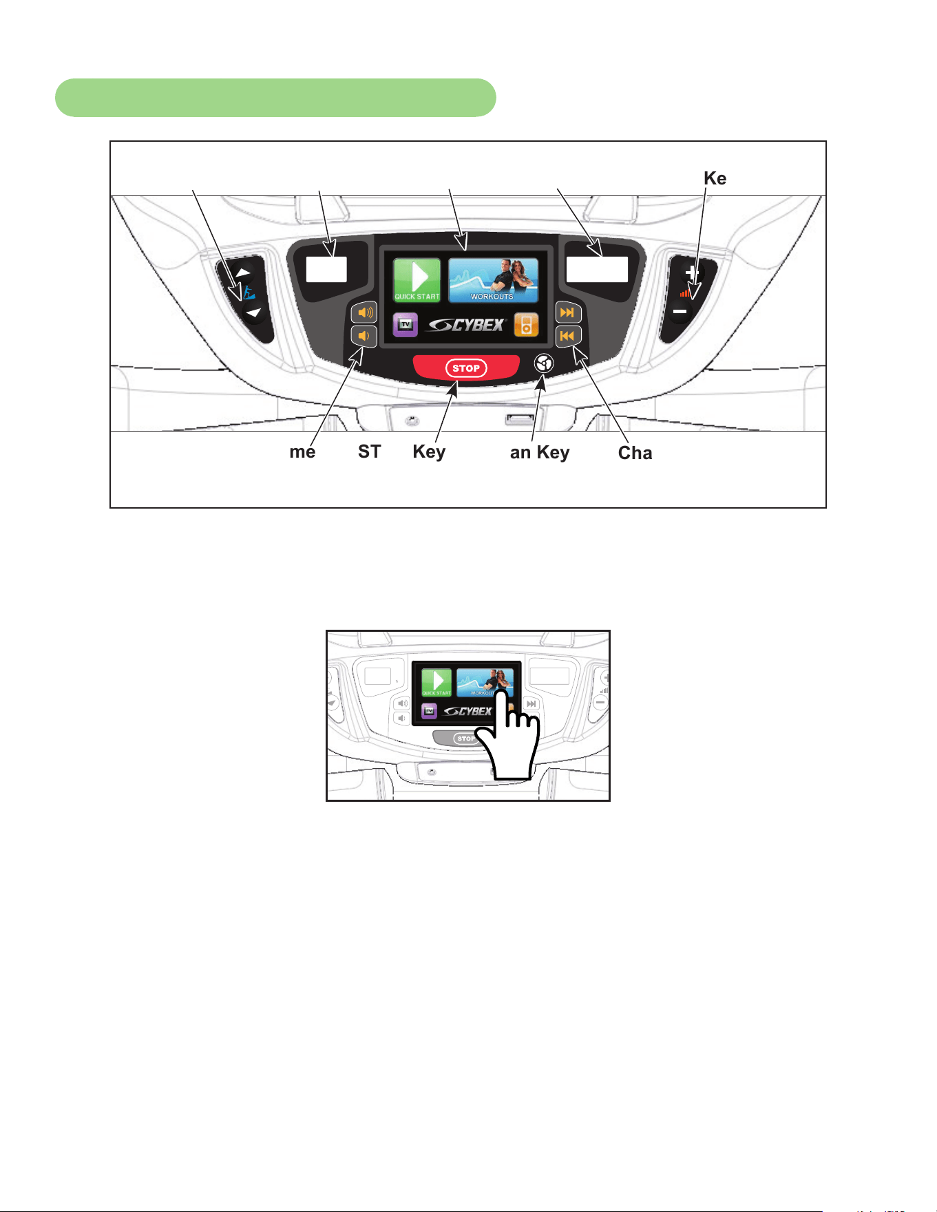
67
Cybex Owner’s Manual
CardioTouch Screen and User Controls
Incline
Display
CardioTouch
Screen
Incline
Keys
Resistance
Keys
STOP KeyVolume
Keys
Channel/Track
Keys
Resistance
Display
Fan Key
Displays — Incline and Resistance are shown in the LED displays.
Keys — User controls for Incline, Resistance, Volume, STOP, Fan and Channel/Track.
CardioTouch Screen — Tap the icons to make selections.

68
Cybex Owner’s Manual
Mount and Dismount
WARNING: Serious injury or death can occur. To avoid injury or death the following
procedure must be followed. Wait until all moving parts come to a complete
stop and foot plates are in starting position before mounting or dismounting.
Mounting or dismounting while foot plates are moving can trip or injure user.
To mount unit safely:
1. Verify unit is off or in Dormant Mode and foot plates are completely stopped.
2. Grasp handrail and step carefully onto foot plates.
To dismount unit safely:
1. Wait until foot plates come to a complete stop.
2. Grasp handrails for support and carefully step off back of unit.
Emergency Dismount
If an emergency stop and dismount is required:
1. Grasp handrails for support.
2. Stop striding.
3. Wait until foot plates come to a complete stop.
4. Continue to hold handrails while carefully stepping off unit.

69
Cybex Owner’s Manual
Range of Motion
The elevation is adjustable up or down in the shape of an arc. The lowest setting of 0 equates to an
arc of 12 degrees, where the highest setting of 20 equates to an arc of 34.5 degrees. There is no
difference in muscles used between different incline positions. Differences exist in the intensity of
muscle activity.
Incline
Resistance
Intensity
High
Low
High
HighLow
Low

70
Cybex Owner’s Manual
Quick Operation Guide
Maximum user weight is 400 lbs. (181 kg).
The following is a quick overview of the operation of the unit. For more information read Detailed
Operation Guide in this chapter.
1. Verify foot plates are completely stopped.
2. Grasp handrail and step carefully onto foot plates. Begin striding.
3. Tap QUICK START on the CardioTouch screen. The CardioTouch screen will display “Starting”
and enter Active Mode.
4. Begin striding.
5. Press the Incline ▲▼ keys to change the incline at any time. The left display will show incline.
6. Press the Resistance + – keys to change the resistance at any time. The right display will
show the current resistance.
7. Press the STOP key at any time to pause.
Detailed Operation Guide
Maximum user weight is 400 lbs. (181 kg).
1. Plug the optional power cord and E3 View Monitor power cord (E3 View Monitor units only)
into a power outlet from a grounded circuit, See Electrical Requirements. Coil up the
remainder of the power cord and place it out of the way. The control panel will light up and be
in the Dormant Mode.
2. Verify foot plates are completely stopped.
3. Grasp handrail and step carefully onto foot plates. Begin striding.
4. Select QUICK START or WORKOUTS.
To select a workout category, tap one of the workout category icons from the workout options screen.
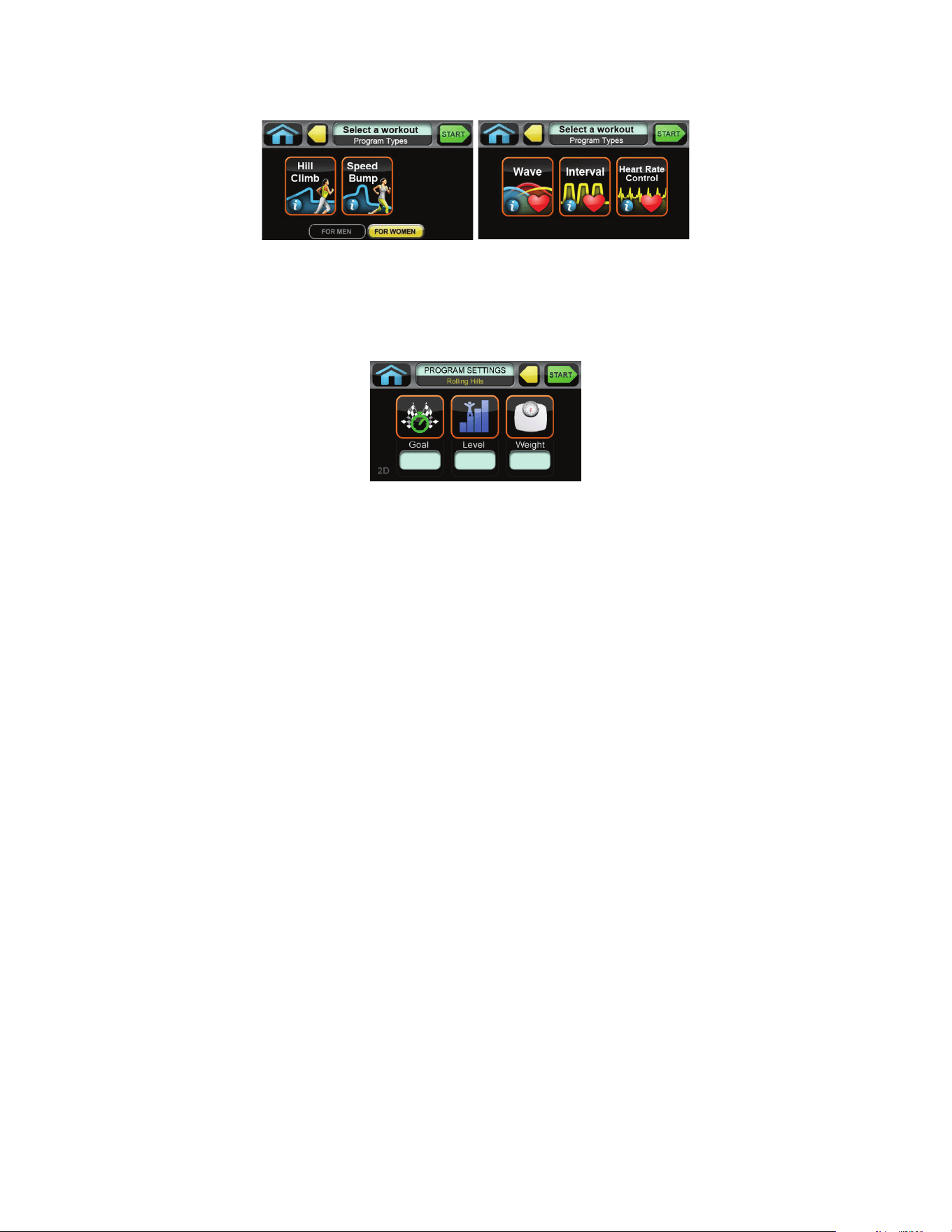
71
Cybex Owner’s Manual
To select a workout, tap one of the workout icons from the workouts screen.
Upon entering a workout the display will guide you through the appropriate settings. This is referred to
as Workout Setup Mode. If the Start key is pressed now, all defaults for that workout will be accepted.
After 10 seconds, if no key has been pressed, the rst default will be accepted. After another 10
seconds the second default will be accepted and so on until the last default.
For the most accurate resistance and calorie count, you must set your correct weight before
beginning your workout (including clothing).
When selecting a workout you must tap the Enter icon after each adjustment of Time, Level or
Weight.
5. Press the Start key. The CardioTouch screen will display “Starting” and enter Active Mode.
6. Begin striding.
7. Observe the control panel. The top center Bar Graph display shows a graphical representation
of the relative incline changes, and if in a workout, will show the relative intensity changes
that are coming up. The Data Readouts will start showing the workout data such as Distance,
Calories, Heart rate (if available), METs and Pace (Minutes per Mile or Minutes per Km). The
data displays will start by automatically shifting every 5 seconds.
Heart rate will be displayed in lieu of METs if a valid heart rate is available from a wireless chest strap
(not included) or by holding the contact heart rate grips.
When you adjust incline in a workout, the change will affect only the current segment. The workout
control will resume starting with the next segment. To increase or decrease overall intensity, adjust
the speed and/or the workout level.
8. Press the Incline ▲▼ keys to change the incline at any time. The left display will show incline.
9. Press the Resistance + – keys to change the resistance at any time. The right display will
show the current resistance.
72
Cybex Owner’s Manual
10.Press the STOP key at any time to pause.
• If pause feature is enabled, pause icon is shown. Press pause icon or STOP button once to
enter pause mode.
• If pause feature is disabled, stop icon is shown. Press stop icon or STOP button once to enter
“Workout review”. “Workout Review” is displayed and the incline returns to 6%.
When a workout is complete the unit begins a countdown, “3...2...1” and sounds a tone for each
count. Workout Review is displayed for the preset time or until you press the Home key. The unit
returns to Dormant Mode when using the optional AC adapter.
Workout Selection
WARNING: Serious injury or death can occur. To avoid injury or death the following
procedure must be followed. Obtain a medical exam before beginning any
exercise program. Begin comfortably with a lower level and progress with
higher levels as you become acclimated.
With the 770A and 770AT you may choose from Quick Start or Workouts. Speed is never
predetermined. Change speed by changing stride.
Quick Start
Press Quick Start. Control incline and resistance.
Workouts
For Men For Women Levels Settings
Weight Loss
Hill Climb Hill Climb 10 Select time, level and weight.
Speed Bump Speed Bump 10 Select time, level and weight.
Strength
High Low High Low 10 Select time, level and weight.
Bursts Bursts 10 Select time, level and weight.
Interval Interval 10 Select time, level and weight.
Fitness Shaping
Total Leg Total Leg 10 Select time, level and weight.
Target: Hip Glute Camp 10 Select time, level and weight.
Cardio
Wave Wave 10 Select time, level and weight.
Interval Interval 10 Select time, level and weight.
Heart Rate Control Heart Rate Control N/A Select time, age, target heart rate and weight.

73
Cybex Owner’s Manual
For Men For Women Levels Settings
Power
Constant Power Constant Power 10 Select time, level and weight.
Adaptive Power Adaptive Power 10 Select time, level and weight.
See Appendix for Workout Overviews
Data Readouts - LED display
As the user exercises, the unit keeps track of and displays the following data:
BPM (Beats Per Minute) – User’s current heart rate. Heart rate will appear when a signal is
introduced.
Calories – The total accumulated calories burned during workout.
Calories Per Hour – Calculation of present workload’s energy exertion in Calories per Hour.
Distance – The total accumulated distance during workout. Depending on the defaults chosen, this
measurement will show in English (miles) or Metric (kilometers). The unit uses a xed 24”
(61 cm) stroke, giving a travel distance of 48” (122 cm) per revolution. Distance = Strides
per Minute x 24” (61 cm) x Time
SPM (Strides per Minute) – The average number of strides per minute at current speed.
MET (Metabolic Equivalent) – Displayed only if no BPM signal is present. A MET is the metabolic
equivalent of the energy expended by the human body at rest.
Anything over one MET is considered exertion. MET are calculated
by the display and updated every 1 – 1.2 seconds. MET = Cal/Hr X
2.2 / User Weight (in pounds).
WATT – Present workload energy exertion. The absolute meter-kilogram-second unit of power equal
to the work done at the rate of one joule per second, equivalent to 1/746 horsepower.
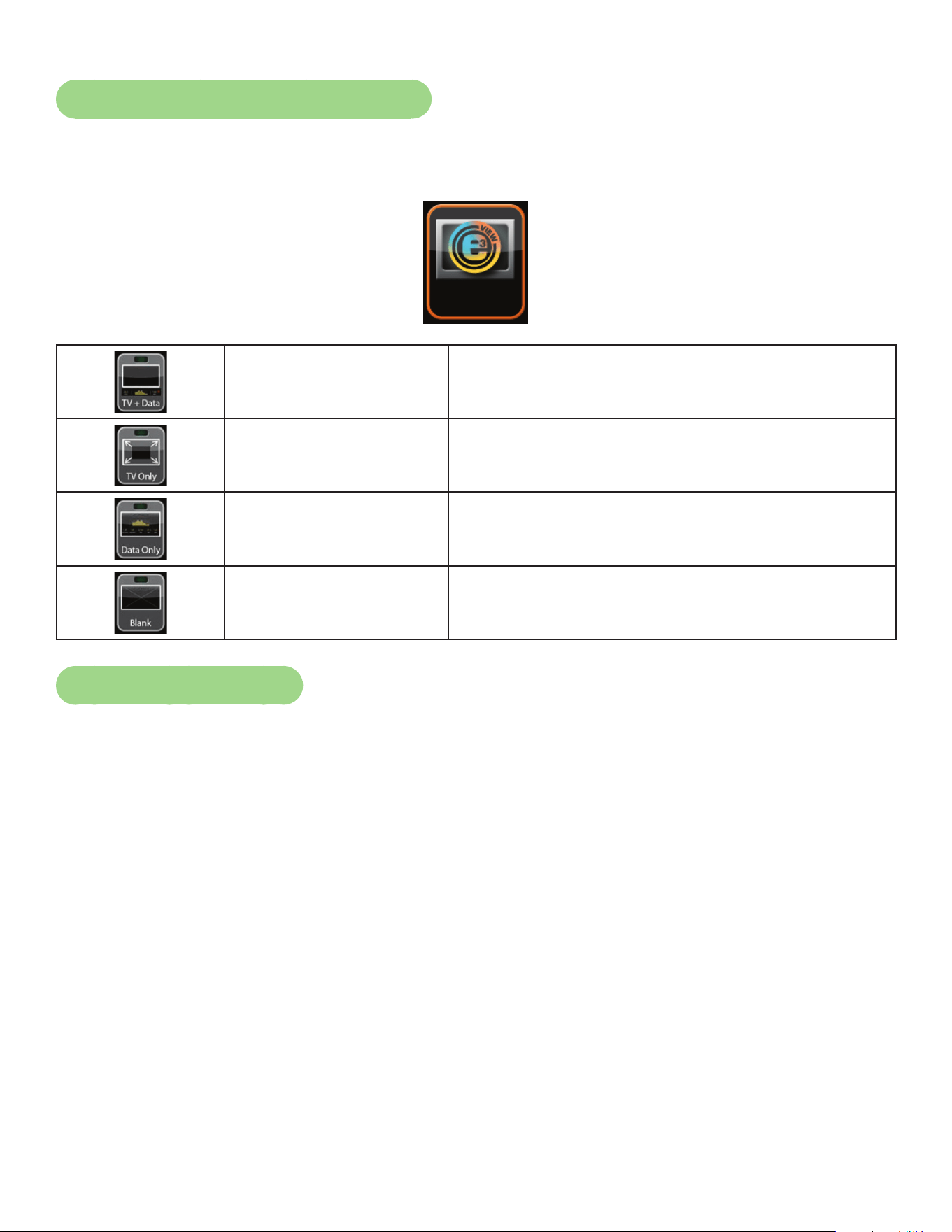
74
Cybex Owner’s Manual
E3 View Monitor Screen Options
During operation four E3 View Monitor screen options are available. Press E3 View Monitor icon to
change screens.
Display
TV + Data Display video with data at bottom of screen
TV Only Display video only
Data Only Display data only
Blank Screen is blank, video and data are not displayed
Heart Rate Indicator
Contact Heart Rate – Lightly hold hand grips on the handlebar ensuring that hands are clean and
contact both the front and back sensors of each grip. A heart rate will display in typically 30 seconds
or less.
Factors that interfere with heart rate signal:
• hand lotions
• oils or body powder
• excessive dirt
• excessive movement
• body composition
• hydration
• too loose grip
• too tight grip
• resting or leaning on grips
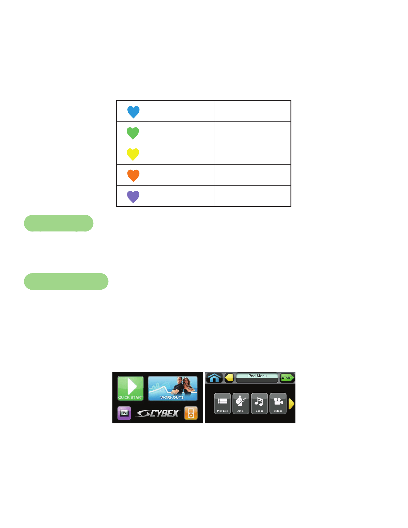
75
Cybex Owner’s Manual
Wireless Heart Rate – To use this feature, a Polar® compatible heart rate transmitter belt (not
included) must be worn.
Once the actual heart rate is determined, the LED to the right of the Data Readouts is blinking to the
displayed BPM and the Heart LED lights up. The color of the light represents a scale of low to high
target heart rate.
Blue 0 – 69 BPM
Green 70 – 93 BPM
Yellow 94 – 119 BPM
Blood Orange 120 – 169
Magenta 170 and higher
Fan Control
The fan defaults to the “OFF” setting. The user can change to “Fan Low”, “Fan High”, or “Fan Off”
setting by pressing the appropriate control key.
iPod Functions
Connecting an iPod — Connecting an iPod to the 770A and 770AT allows the unit to control the
iPod through the CardioTouch screen and charges the iPod.
1. Connect iPod (not supplied) into the 30 pin connector in the right side accessory tray.
2. Place iPod (not supplied) onto the right side accessory tray.
iPod Playlist — Select the iPod icon to display the iPod navigation screen.
• If iPod is already playing use the standard iPod controls.
• If iPod is Dormant make a selection from the iPod Menu.
• Once a selection is made from the iPod menu, make further selections until music or videos are
found.
76
Cybex Owner’s Manual
Maintenance
All preventive maintenance activities must be performed on a regular basis. Performing routine
preventive maintenance actions can aid in providing safe, trouble-free operation of all Cybex Strength
Systems equipment.
Cybex is not responsible for performing regular inspection and maintenance actions for your
machines. Instruct all personnel in equipment inspection and maintenance actions and also in
accident reporting/recording. Cybex representatives are available to answer any questions that you
may have.
Allinspectionsandrepairsmustbeperformedbytrainedservicepersonnelonly.Cybexwill
voidwarrantyifnon-Cybexreplacementpartsareused.
Use only Cybex replacement
parts when servicing.
Failure to do so could result
in personal injury.
Cybex will void warranty if
non-Cybex replacement parts
are used.
CAUTION
Warnings
Read all warnings in this chapter and in the Safety Section.
Observe the following warnings and cautions:
• All maintenance activities shall be performed by qualied personnel. Failure to do so could result in
serious injury.
• To prevent electrical shock, verify unit is unplugged from the electrical outlet before performing any
cleaning or maintenance procedures. A charge can remain after unplugging the optional power
cord.
• Keep wet items away from inside parts of unit.
• Performance level of equipment can be maintained only if it is examined regularly for damage and
wear. Pay special attention to components most susceptible to wear.
• Replace worn or damaged components immediately and/or keep the equipment out of use until
repair is completed.

77
Cybex Owner’s Manual
Cleaning Unit
1. Spray a clean cloth with a mild cleaning agent, such as a water and dish soap solution.
2. Wipe unit.
Do not spray cleaning solution directly on unit. Direct spraying could cause damage to electronics and
may void warranty.
After Each Use:
• Wipe up any liquid spills immediately.
• Wipe up any remaining perspiration from handles and painted surfaces.
• Be careful not to spill or get excessive moisture on the console and display overlays, as this might
create an electrical hazard or cause failure of the electronics.
• Clean heart rate grips using a cloth dampened with a cleaning solution containing alcohol.
The heart rate grips are the only part of the unit where a cleaning solution containing alcohol should
be used.
Preventive Maintenance Activities
Perform regular preventive maintenance to ensure normal operation of unit. Keep a log of all
maintenance actions to assist in staying current with all preventive maintenance activities.
Cybex is not responsible for performing regular inspection and maintenance actions for your unit.
Instruct all personnel in equipment inspection and maintenance actions and also in accident reporting/
recording. Contact Cybex Customer Service at 888-462-9239 or 508-533-4300 for any preventive
maintenance or service concerns.
Read and understand warnings listed in this chapter and in the Safety Section. Read and
understand all instructions in this section.
During maintenance, disconnect the external power source. If unit has the optional AC Power Kit
or and E3 View Monitor power cord (E3 View Monitor units only) unplug the power cord(s) from the
power outlet.
For some maintenance activities it will be necessary to remove and replace the access cover.
Tool Required
Phillips screwdriver
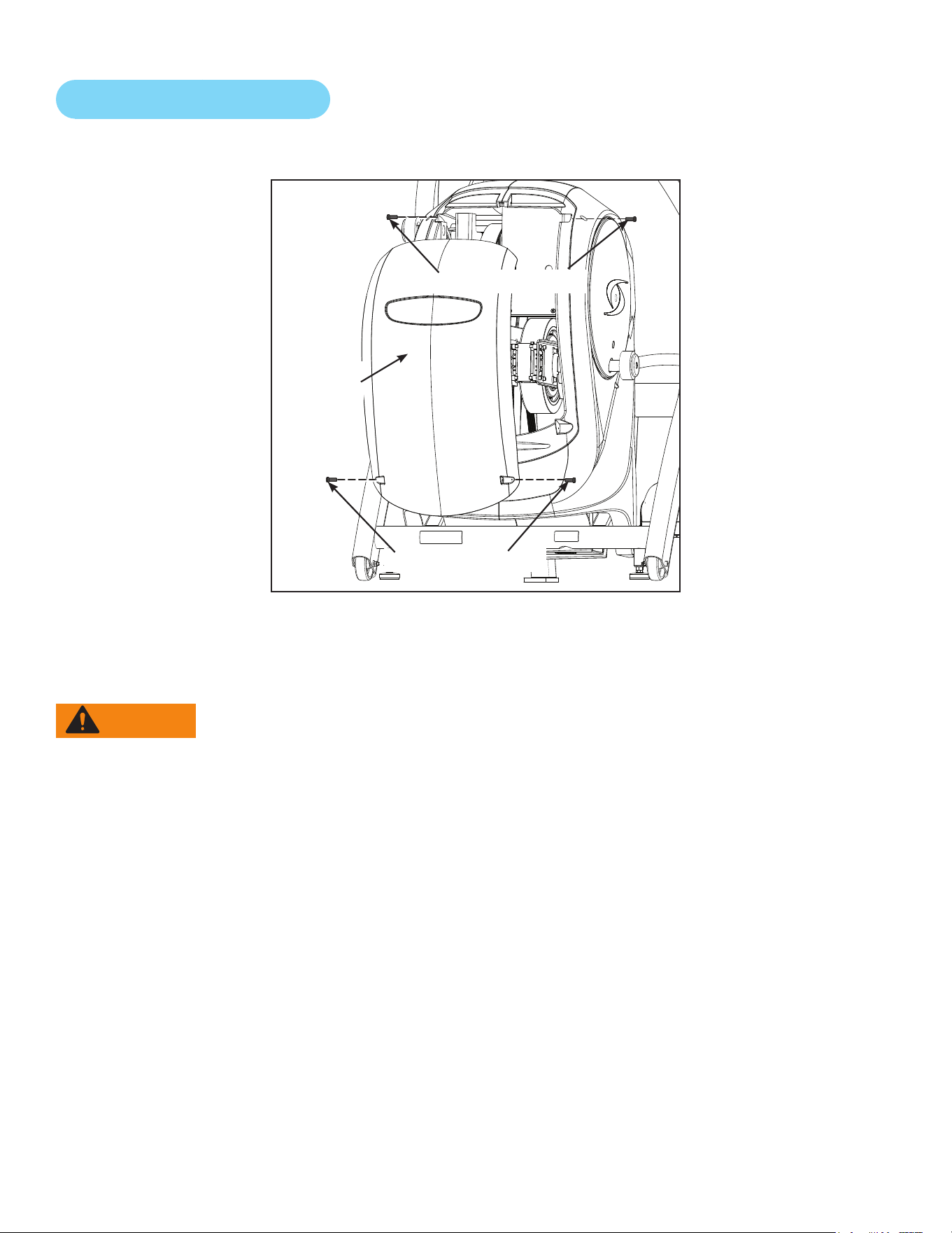
78
Cybex Owner’s Manual
Remove Access Cover
1. Remove the two lower screws securing the access cover using a Phillips screwdriver.
Lower Screws (2)
Access
Cover
Upper Screws (2)
2. Remove two upper screws securing the access cover using a Phillips screwdriver. Refer to the
above diagram.
3. Remove the access cover.
WARNING: Serious injury or death can occur. To avoid injury or death the following
procedure must be followed. Wait until ywheel cools before servicing. A hot
ywheel may burn user.
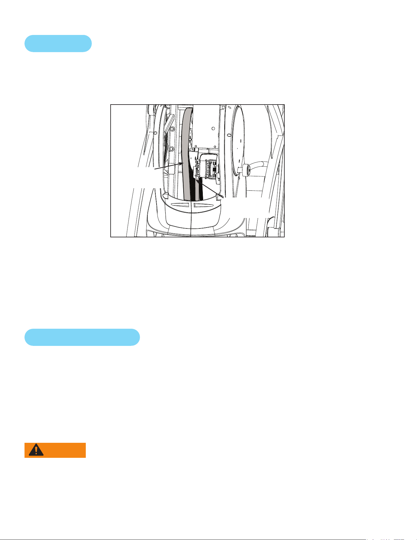
79
Cybex Owner’s Manual
Drive Belts
There are two drive belts that may become loose, worn or cracked.
Unless the belts have been removed and not replaced properly, it is unlikely the belts will come loose
or need to be re-tensioned.
Primary
Drive Belt
Secondary
Drive Belt
If a belt has cracks or appears worn, it must be replaced immediately by a qualied service
technician.
Primary Belt – The wider of the two belts. It has grooves that keep it aligned on the large upper
pulley.
Secondary Belt – The narrower of the two belts. It has grooves that keep it aligned on the ywheel’s
drive pulley.
Rechargeable Battery
The unit is designed with a 12 volt Lead-Acid rechargeable battery. The battery will recharge during
regular operation of unit or when the optional power adapter is plugged in.
The display will indicate dashes in the incline display if the battery fails to provide enough energy. The
unit will still function normally other than the disabling of the incline feature.
If the battery is completely discharged, the workout review will also be truncated if the user is not
striding during the time period. See Customer Service for contact information to replace the battery
or purchase the optional AC adapter kit.
WARNING: Serious injury or death can occur. To avoid injury or death the following
procedure must be followed. Battery replacement shall be performed by
qualied service technician.
Removebatteryanddisposeofsafelybeforeunitdisposal.

80
Cybex Owner’s Manual
Attach Access Cover
Do not over tighten screws.
1. Replace and tighten the two upper screws removed in step 2 Remove Access Cover using a
Phillips screwdriver.
2. Replace and tighten the two lower screws removed in step 1 Remove Access Cover using a
Phillips screwdriver.
3. Test unit for proper operation.
E3 View Monitor
Cleaning
1. Unplug E3 View Monitor power cord from the wall socket.
2. Dust off the panel with a soft dry cloth as needed. The screen can be cleaned with computer
screen wipes or other non-abrasive, moist, disposable wipes.
Storage or Long Non-Use Periods
When not using product for an extended period of time the product should be disconnected from the
Power Supply, TV/Cable Signal Feed, Fitness Equipment and any Peripheral Devices.
Pixels
Very small red, blue, white or green spots may be visible or may appear on the screen. This is a
characteristic of liquid crystal display panels and is not a faulty condition. The liquid crystal panel is
built with very high precision technology giving ne picture details. Occasionally, a few non-active
pixels may appear on the screen as a xed point. This does not affect the performance of monitor or
merit a warranty claim.
Maintenance
• It is very important to have the unit regularly examined by a qualied technician to ensure the
product is t for use.
• If the unit malfunctions, please refer to a qualied technician for repair or replacement of defective
parts immediately. Do not attempt to use the monitor until it has been inspected and repaired by a
qualied technician.
• For inspection, installation and servicing, please consult qualied technician.
• Failure to use a manufacturer approved repair technician may void any warranty claims.

81
Cybex Owner’s Manual
Recommended Service Schedule
All maintenance activities shall be performed by qualied personnel. Failure to do so could result in
serious injury.
This is the minimum recommended service.
Determinedistance.
1. Press the Cybex logo icon
to display the Access Toolbox and Lock Screen
options.
2. Press the Access Toolbox icon to access the Toolbox login screen.
3. Enter the sequence:
.
4. Press the Statistics icon to access the Recorded Statistics screen.
5. Locate and tap the icon for Arc Trainer Totals.
6. Record Distance.
7. Exit Set Up Mode by tapping the Toolbox icon , then tap the Home icon . The screen
will refresh.
First 500 Miles (800 KM)
Follow this procedure to ensure the belts are tensioned properly and in good condition.
1. Remove access cover. (See previous procedure Remove Access Cover)
2. Pull down and roll each belt to examine the condition. If a belt has cracks or appears worn, it
must be replaced immediately by a qualied service technician.
3. Attach access cover. (See previous procedure Attach Access Cover)
Every 5000 Miles (8000 KM)
Check drive belts for tension and wear. (See procedure First 500 Miles)
Move unit and vacuum underneath. Lift the rear of unit and roll it back from its present
position. Vacuum underneath and return unit to normal position.
Clean inside unit.
1. Remove access cover. (See previous procedure Remove Access Cover)
2. Using a vacuum cleaner attachment or hand vacuum, clean the exposed components.
3. Remove dirt and debris from internal components.
4. Using a dry cloth, wipe all exposed areas.
5. Attach access cover. (See procedure Attach Access Cover)
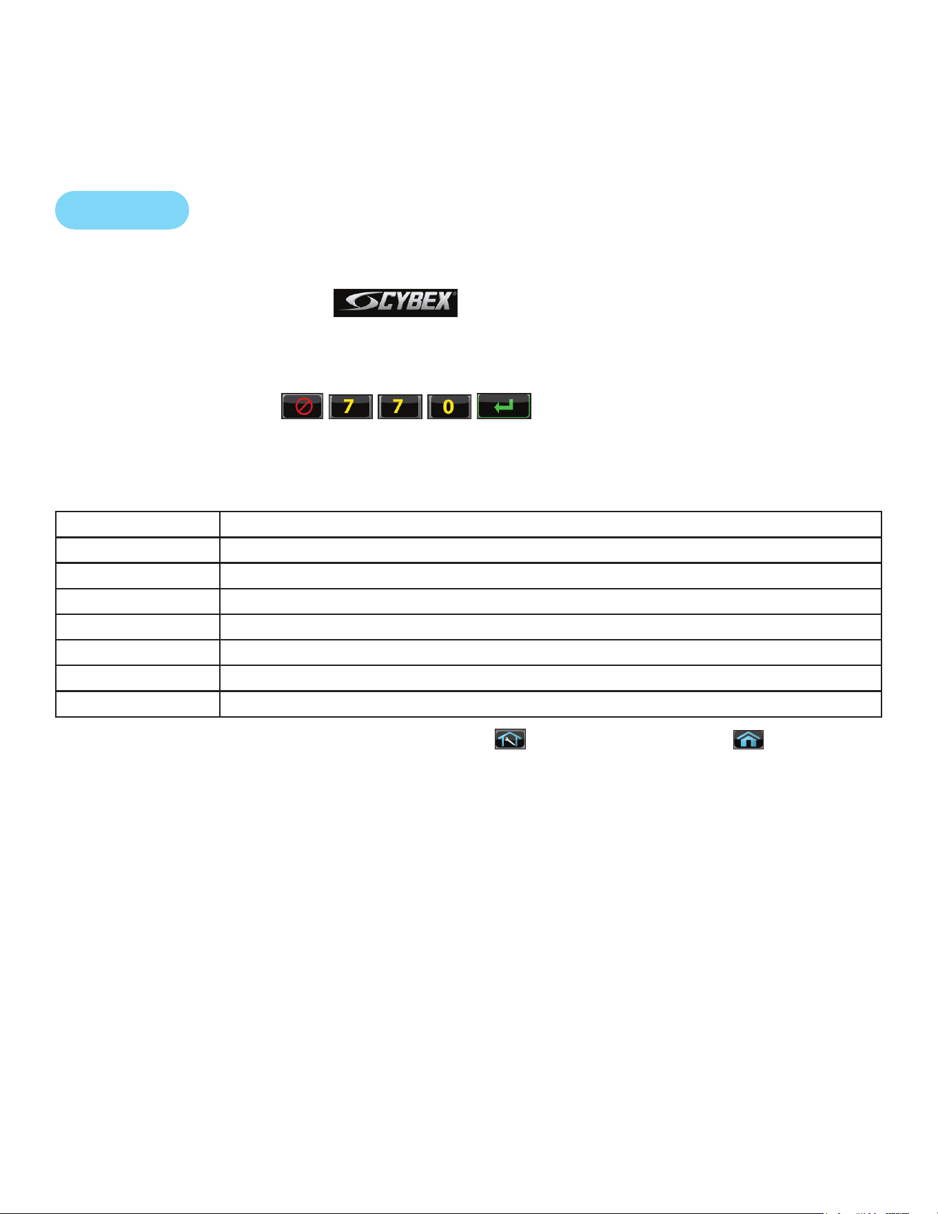
82
Cybex Owner’s Manual
Every 20,000 Miles (32000 KM)
Contact qualied service technician to check elevation assembly, replace any worn parts and
lubricate elevation bushings.
Statistics
The Statistics screen allows tracking of equipment usage.
1. Press the Cybex logo icon
to display the Access Toolbox and Lock Screen
options.
2. Press the Access Toolbox icon to access the Toolbox login screen.
3. Enter the sequence:
.
4. Press the Statistics icon to access the Recorded Statistics screen.
5. Locate and tap the icon for Arc Trainer Totals.
Statistics Menu Display
Distance Total accumulated miles or KM
Hours Total time in active mode
Starts Total number of workout sessions
Moves Number of incline moves in 1% increments
On Time Total number of hours the console has been on
On Battery Total number of minutes the battery has been used
Days in svc Number of days since install date
6. Exit Set Up Mode by tapping the Toolbox icon
, then tap the Home icon . The screen
will refresh.

83
Cybex Owner’s Manual
Customer Service
Product Registration
To register product do the following:
1. Visit www.cybexintl.com.
2. Locate Product Registration in the Support section.
3. Fill out form completely.
4. Click the Submit button to register product.
Contacting Service
Hours of phone service are Monday through Friday from 8:30 a.m. to 6:00 p.m. Eastern Standard
Time.
For Cybex customers living in the USA, contact Cybex Customer Service at 888-462-9239.
For Cybex customers living outside the USA, contact Cybex Customer Service at 508-533-4300 or
fax 508-533-5183. email address [email protected]
Find information on the web at www.cybexintl.com.
Ordering Parts
To order parts online go to www.cybexintl.com.
To speak with a customer service representative, call 888-462-9239 (for customers living within the
USA) or 508-533-4300 (for customers outside the USA).
The following information located on the serial number decal will assist our Cybex representatives in
serving you.
• Unit Serial Number, Product Name and Model Number
• Part Description and Part Number if you have it. All parts can be found on the web
at www.cybexintl.com
• Shipping Address
• Contact Name
• Include a description of the problem.
In addition to your shipping address and contact name, your account number is helpful but not
required. You may also fax orders to 508-533-5183.
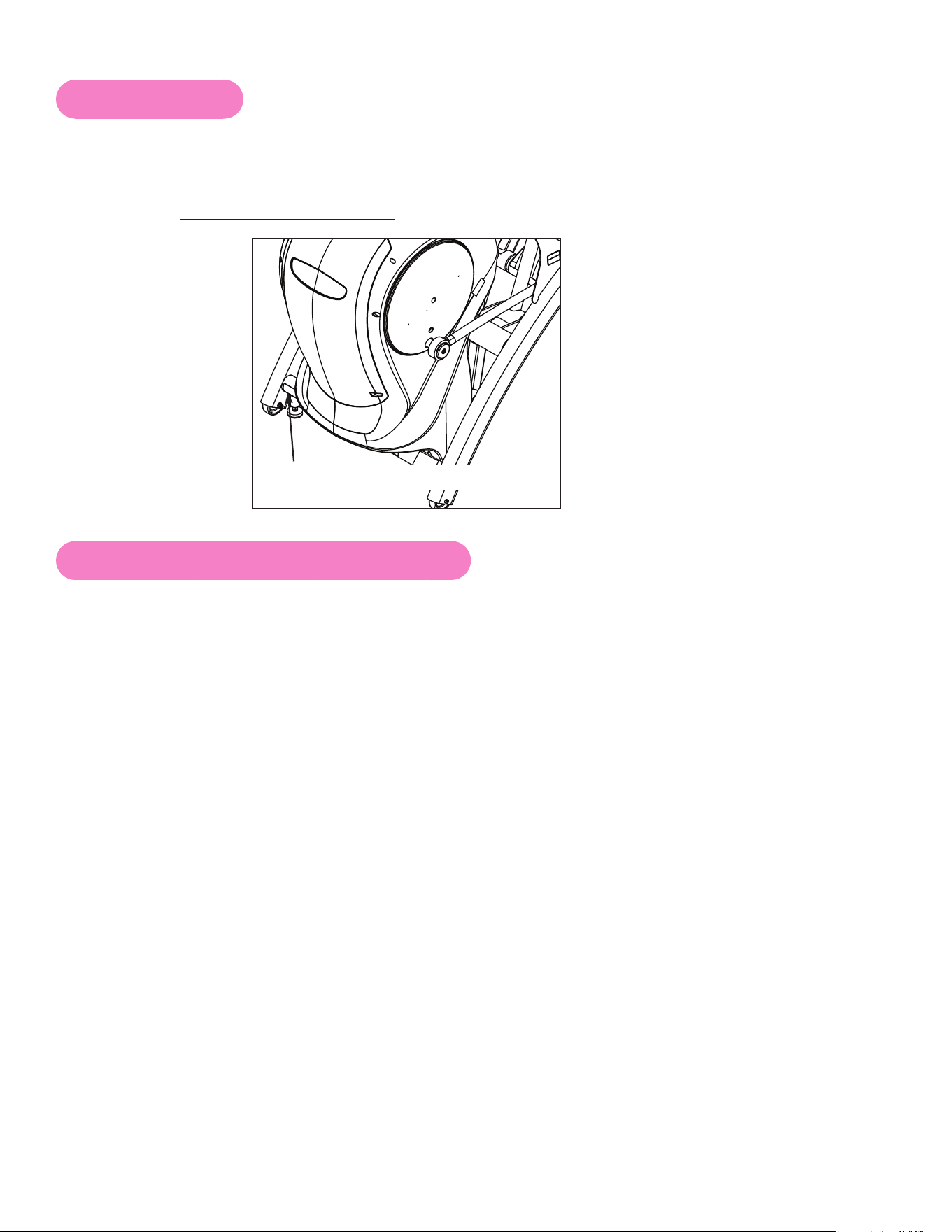
84
Cybex Owner’s Manual
Serial Number
The serial number can be found on the front of your unit. For your convenience, record your serial
number below so that you will have it ready if you call Cybex Customer Service.
Serial Number
Serial Number Location
Return Material Authorization (RMA)
The Return Material Authorization (RMA) system is used when returning material for placement,
repair or credit. The system assures that returned materials are properly handled and analyzed.
Follow the following procedures carefully.
Contact your authorized Cybex dealer on all warranty-related matters. Your local Cybex dealer will
request a RMA from Cybex, if applicable. Under no circumstances will defective parts or equipment
be accepted by Cybex without proper RMA and an Automated Return Service (ARS) label.
Please contact Cybex Customer Service for the return of any item that is defective.
Provide the technician with a detailed description of the problem you are having or the defect in the
item you wish to return. Provide the model and serial number of your Cybex equipment.
At Cybex’s discretion, the technician may request that you return the problem part(s) to Cybex for
evaluation and repair or replacement. The technician will assign you a RMA number and will send
you an ARS label. The ARS label and the RMA numbers must be clearly displayed on the outside
of the package that contains the item(s) to be returned. Include the description of the problem, the
serial number of the equipment and the name and address of the owner in the package along with the
part(s).
Merchandise returned without an RMA number on the outside of the package or shipments sent COD
will not be accepted by the Cybex receiving department.

85
Cybex Owner’s Manual
Damaged Parts
Materials damaged in shipment should not be returned for credit. Shipping damages are the
responsibility of the carrier (UPS, Federal Express, trucking companies, etc.)
Apparent Damage
Upon receipt of your shipment, check all items carefully. Any damage seen with a visual check must
be noted on the freight bill and signed by the carrier’s agent. Failure to do so will result in the carriers
refusal to honor your damage claim. The carrier will provide you with the required forms for ling such
claims.
Concealed Damage
Damage not seen with a visual check upon receipt of a shipment but notices later must be reported
to the carrier as soon as possible. Upon discovery of the damage, a written or phone request to
the carrier asking them to perform an inspection of the materials must be made within ten days of
the delivery date. Keep all shipping containers and packing materials as they will be needed in the
inspection process. The carrier will provide you with an inspection report and the necessary forms for
ling a concealed damage claim. Concealed damage claim is the carrier’s responsibility.
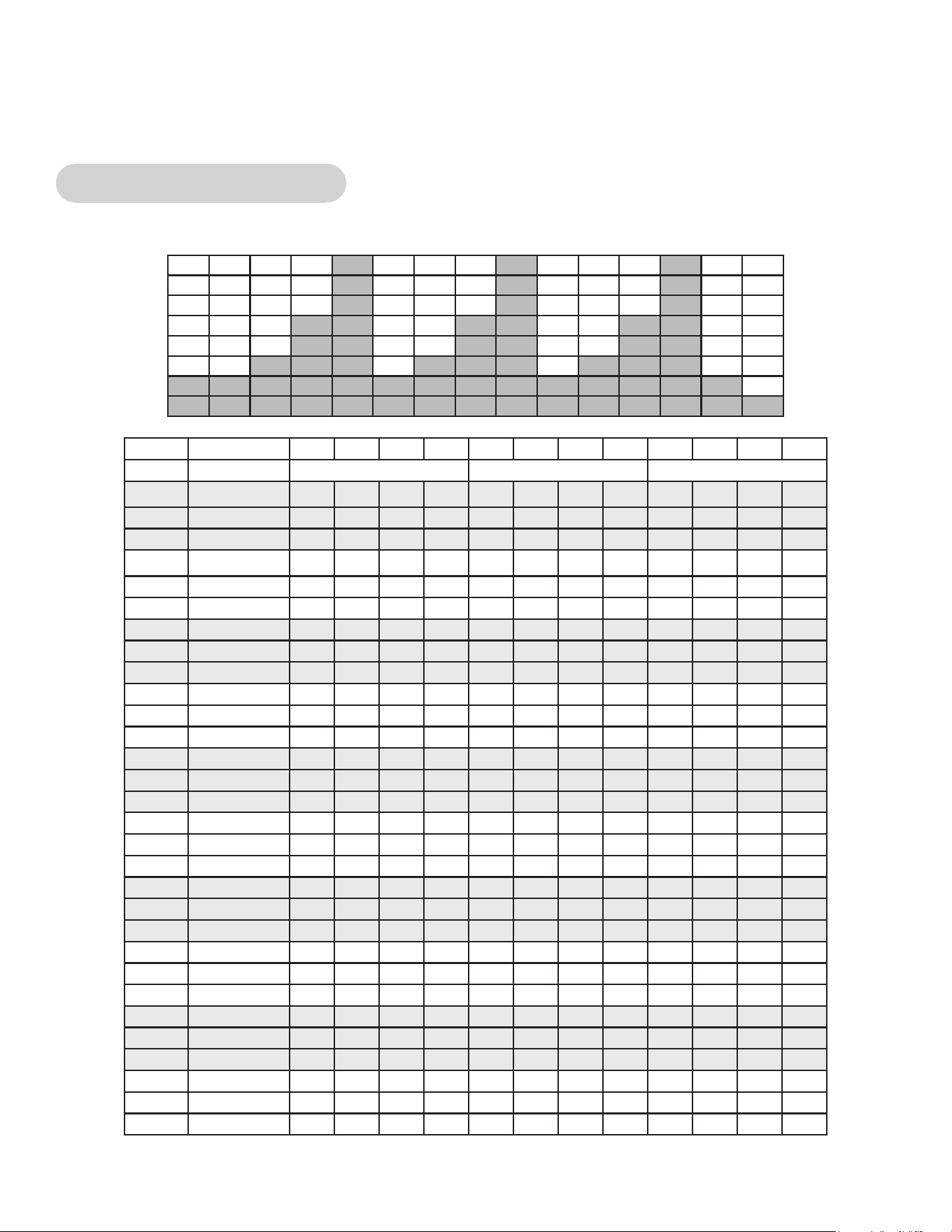
86
Cybex Owner’s Manual
Appendix - Workout Overviews
Weight Loss - Hill Climb
A gentle calorie burner with steady work increases over 3 minutes followed by a 1 minute rest.
Time :30 :30 :30 :30 1:00 1:00 1:00 1:00 :30 :30 :30 :30
Level Warm Up Core Cool Down
10 Resistance 30 30 35 35 40 45 50 15 15 15 15 15
10 Incline 6 10 12 12 14 16 18 6 6 6 6 6
10 Target Pace 110 110 110 110 110 110 110 80 80 80 80 80
9 Resistance 25 25 30 30 35 40 45 15 15 15 15 15
9 Incline 6 8 10 10 12 14 16 6 6 6 6 6
9 Target Pace 110 110 110 110 110 110 110 80 80 80 80 80
8 Resistance 20 20 25 25 30 35 40 15 15 15 10 10
8 Incline 6 6 8 8 10 12 14 6 6 6 6 6
8 Target Pace 110 110 110 110 110 110 110 80 80 80 80 80
7 Resistance 15 15 20 20 25 30 35 10 10 10 10 10
7 Incline 6 4 6 6 8 10 12 4 6 6 6 6
7 Target Pace 110 110 110 110 110 110 110 80 80 80 80 80
6 Resistance 10 10 15 15 20 25 30 10 10 10 10 10
6 Incline 6 2 4 4 6 8 10 4 6 6 6 6
6 Target Pace 110 110 110 110 110 110 110 80 80 80 80 80
5 Resistance 10 10 10 10 15 20 25 10 10 10 5 5
5 Incline 6 2 2 2 4 6 8 2 6 6 6 6
5 Target Pace 110 110 110 110 110 110 110 80 80 80 80 80
4 Resistance 5 5 5 5 10 15 20 5 5 5 5 5
4 Incline 6 2 2 2 2 4 6 2 6 6 6 6
4 Target Pace 110 110 110 110 110 110 110 80 80 80 80 80
3 Resistance 5 5 5 5 10 15 15 5 5 5 5 5
3 Incline 6 2 2 2 2 4 4 2 6 6 6 6
3 Target Pace 110 110 110 110 110 110 110 80 80 80 80 80
2 Resistance 5 5 5 5 5 10 15 5 5 5 5 5
2 Incline 6 0 0 0 0 2 4 0 6 6 6 6
2 Target Pace 110 110 110 110 110 110 110 80 80 80 80 80
1 Resistance 5 5 5
5 5 10 10 5 5 5 5 5
1 Incline 6 0 0 0 0 2 2 0 6 6 6 6
1 Target Pace 110 110 110 110 110 110 110 80 80 80 80 80
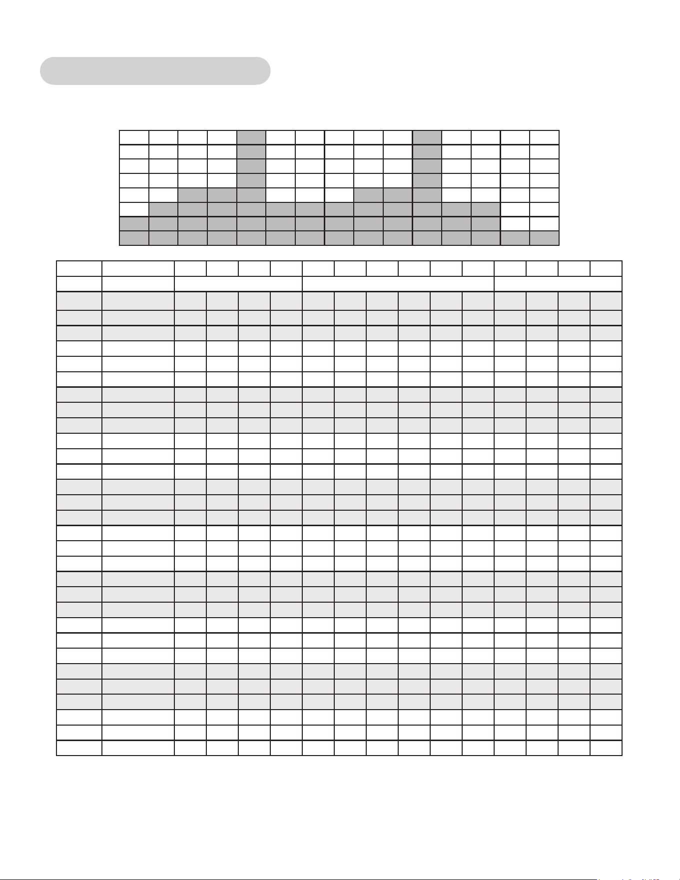
87
Cybex Owner’s Manual
Weight Loss - Speed Bump
A relatively steady workload includes a high output bump for increased energy expenditure.
Time :30 :30 :30 :30 1:00 1:00 1:00 1:00 1:00 1:00 :30 :30 :30 :30
Level Warm Up Core Cool Down
10 Resistance 25 25 30 30 35 35 55 25 25 25 20 20 20 20
10 Incline 6 4 6 6 6 6 10 2 2 2 6 6 6 6
10 Target Pace 110 110 110 110 110 110 130 110 110 100 100 100 100 100
9 Resistance 20 20 25 25 30 30 50 20 20 20 15 15 15 15
9 Incline 6 4 6 6 6 6 10 2 2 2 6 6 6 6
9 Target Pace 110 110 110 110 110 110 130 110 110 100 100 100 100 100
8 Resistance 20 20 25 25 30 30 50 20 20 20 15 15 15 15
8 Incline 6 4 6 6 6 6 8 2 2 2 6 6 6 6
8 Target Pace 110 110 110 110 110 110 130 110 110 100 100 100 100 100
7 Resistance 20 20 25 25 30 30 50 20 20 20 15 15 15 15
7 Incline 6 4 6 6 6 6 8 2 2 2 6 6 6 6
7 Target Pace 110 110 110 110 110 110 120 110 110 100 100 100 100 100
6 Resistance 15 15 20 20 25 25 45 20 20 20 10 10 10 10
6 Incline 6 4 6 6 6 6 8 2 2 2 6 6 6 6
6 Target Pace 110 110 110 110 110 110 120 110 110 100 100 100 80 80
5 Resistance 15 15 20 20 25 25 40 20 20 20 10 10 10 10
5 Incline 6 2 4 4 4 4 6 2 2 2 6 6 6 6
5 Target Pace 110 110 110 110 110 110 120 110 110 100 100 100 80 80
4 Resistance 10 10 15 15 20 20 40 15 15 15 10 10 10 10
4 Incline 6 0 2 2 2 2 6 2 2 2 6 6 6 6
4 Target Pace 100 100 100 100 100 100 110 100 100 80 80 80 80 80
3 Resistance 10 10 15 15 20 20 35 15 15 15 10 10 10 10
3 Incline 6 0 0 0 0 2 4 2 2 0 6 6 6 6
3 Target Pace 100 100 100 100 100 100 110 100 100 80 80
80 80 80
2 Resistance 5 5 10 10 15 15 30 15 15 15 5 5 5 5
2 Incline 6 0 0 0 0 2 4 2 2 0 6 6 6 6
2 Target Pace 100 100 100 100 100 100 110 100 100 80 80 80 80 80
1 Resistance 5 5 10 10 15 15 30 15 15 15 5 5 5 5
1 Incline 6 0 0 0 0 0 4 0 0 0 6 6 6 6
1 Target Pace 100 100 100 100 100 100 100 100 100 80 80 80 80 80
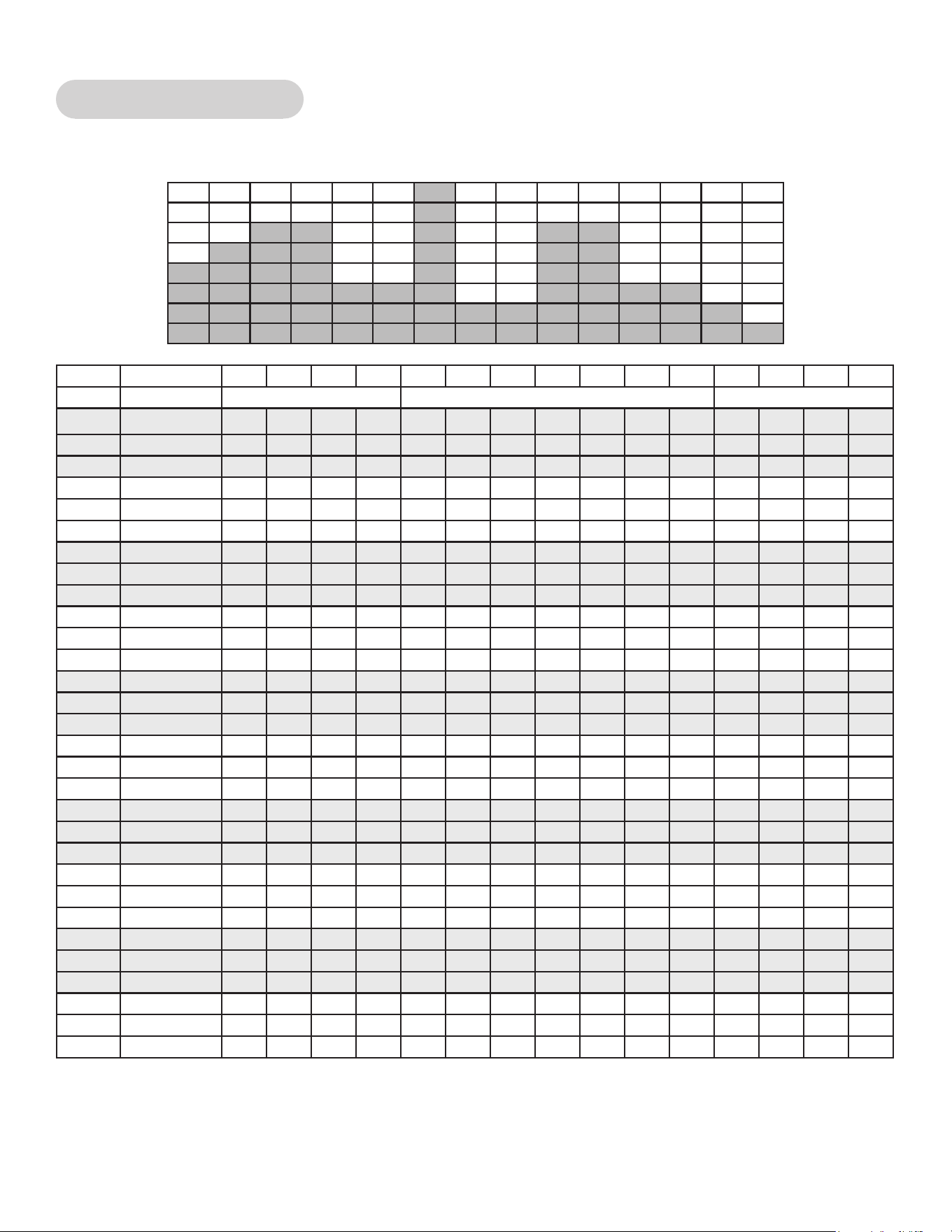
88
Cybex Owner’s Manual
Strength - High Low
Two levels of intensity and duration help develop muscular strength and endurance.
Time :30 :30 :30 :30 1:00 1:00 1:00 1:00 1:00 1:00 1:00 :30 :30 :30 :30
Level Warm Up Core Cool Down
10 Resistance 60 60 65 65 65 65 30 30 100 30 30 30 25 20 20
10 Incline 6 14 16 18 20 20 20 20 20 16 16 6 6 6 6
10 Target Pace 110 110 110 110 110 110 110 110 110 110 110 100 100 100 100
9 Resistance 55 55 60 60 60 60 25 25 95 25 25 25 20 20 20
9 Incline 6 12 14 16 18 18 18 18 18 14 14 6 6 6 6
9 Target Pace 110 110 110 110 110 110 110 110 110 110 110 100 100 100 100
8 Resistance 50 50 55 55 55 55 25 25 90 25 25 25 20 20 20
8 Incline 6 10 12 14 16 16 16 16 16 12 12 6 6 6 6
8 Target Pace 110 110 110 110 110 110 110 110 110 110 110 100 100 100 100
7 Resistance 45 45 50 50 50 50 20 20 75 20 20 20 20 15 15
7 Incline 6 10 12 14 16 16 16 16 16 12 12 6 6 6 6
7 Target Pace 110 110 110 110 110 110 110 110 110 110 110 100 100 100 100
6 Resistance 40 40 45 45 45 45 20 20 65 20 20 20 20 15 15
6 Incline 6 8 10 12 14 14 14 14 14 10 10 6 6 6 6
6 Target Pace 110 110 110 110 110 110 110 110 110 110 110 100 100 100 100
5 Resistance 35 35 40 40 40 40 15 15 55 15 15 15 15 10 10
5 Incline 6 8 10 12 14 14 14 14 14 10 10 6 6 6 6
5 Target Pace 110 110 110 110 110 110 110 110 110 110 110 100 100 100 100
4 Resistance 30 30 35 35 35 35 15 15 45 15 15 15 15 10 10
4 Incline 6 6 8 10 12 12 12 12 12 8 8 6 6 6 6
4 Target Pace 110 110 110 110 110 110 110 110 110 110 110 100 100 100 100
3 Resistance 25 25 30 30 30 30 10 10 35 10 10 10 10 10 10
3 Incline 6 6 8 10
12 12 12 12 12 8 8 6 6 6 6
3 Target Pace 110 110 110 110 110 110 110 110 110 110 110 100 100 100 100
2 Resistance 20 20 25 25 25 25 10 10 30 10 10 10 10 10 10
2 Incline 6 4 6 8 10 10 10 10 10 6 6 6 6 6 6
2 Target Pace 110 110 110 110 110 110 110 110 110 110 110 100 100 100 100
1 Resistance 15 15 20 20 20 20 10 10 25 10 10 10 10 10 10
1 Incline 6 4 6 8 10 10 10 10 10 6 6 6 6 6 6
1 Target Pace 110 110 110 110 110 110 110 110 110 110 110 100 100 100 100
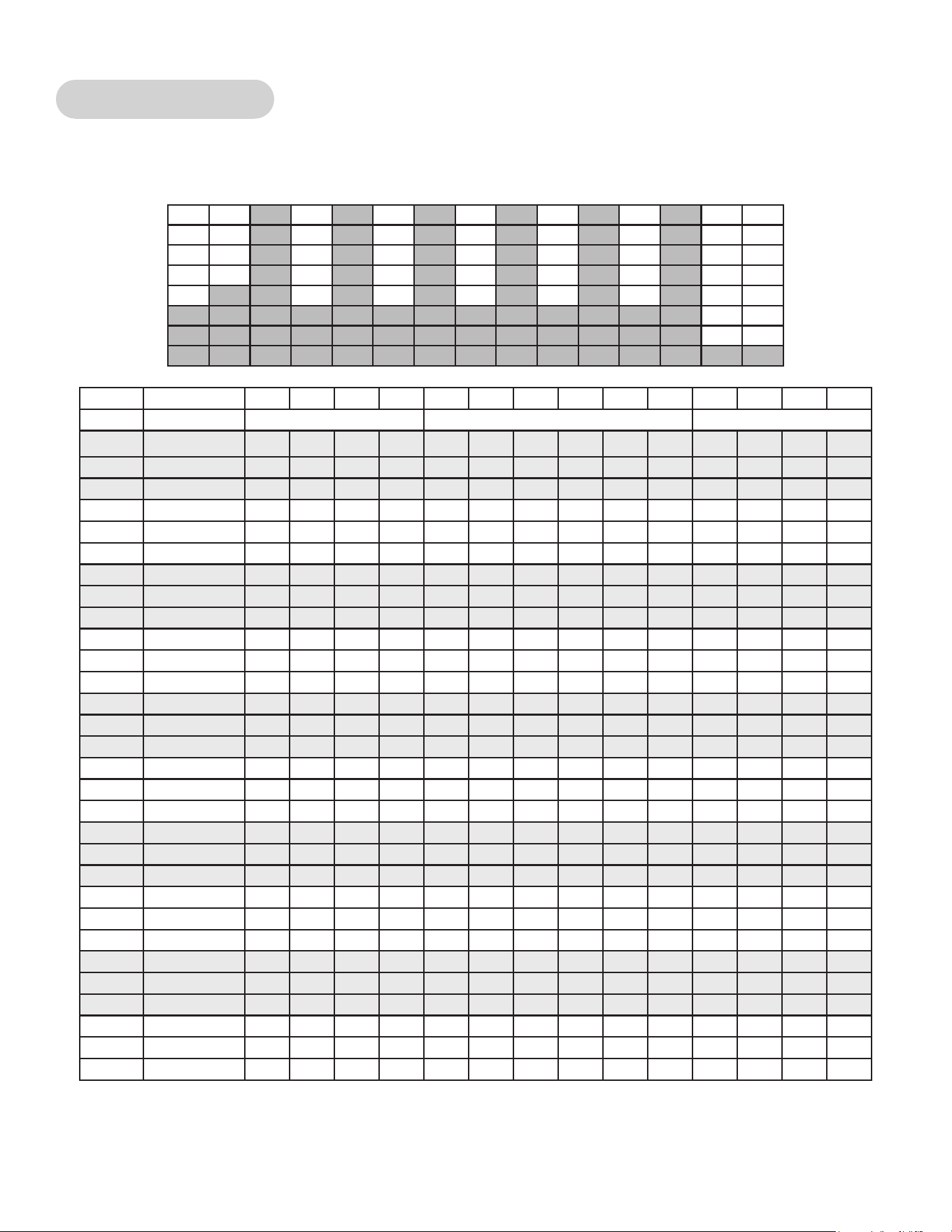
89
Cybex Owner’s Manual
Strength - Bursts
Brief high-intensity segments are mixed with longer and easier intervals developing strength and
aerobic capacity.
Time :30 :30 :30 :30 1:00 1:00 1:00 1:00 1:00 1:00 :30 :30 :30 :30
Level Warm Up Core Cool Down
10 Resistance 50 50 55 55 80 50 80 50 80 50 40 40 30 30
10 Incline 6 14 16 18 20 18 20 18 20 12 6 6 6 6
10 Target Pace 100 100 110 110 120 110 120 110 120 80 100 100 100 100
9 Resistance 45 45 50 50 75 45 75 45 75 45 35 35 25 25
9 Incline 6 14 16 18 20 18 20 18 20 12 6 6 6 6
9 Target Pace 100 100 110 110 120 110 120 110 120 80 100 100 100 100
8 Resistance 40 40 45 45 70 40 70 40 70 40 30 30 20 20
8 Incline 6 14 16 18 20 18 20 18 20 12 6 6 6 6
8 Target Pace 100 100 110 110 120 110 120 110 120 80 100 100 100 100
7 Resistance 35 35 40 40 65 35 65 35 65 35 25 25 15 15
7 Incline 6 12 14 16 18 16 18 16 18 10 6 6 6 6
7 Target Pace 100 100 110 110 120 110 120 110 120 80 100 100 100 100
6 Resistance 30 30 35 35 60 30 60 30 60 30 20 20 10 10
6 Incline 6 10 12 14 16 14 16 14 16 8 6 6 6 6
6 Target Pace 100 100 110 110 120 110 120 110 120 80 100 100 100 100
5 Resistance 25 25 30 30 55 25 55 25 55 25 15 15 10 5
5 Incline 6 8 10 12 14 12 14 12 14 6 6 6 6 6
5 Target Pace 100 100 110 110 120 110 120 110 120 80 100 100 100 100
4 Resistance 20 20 25 25 50 20 50 20 50 20 10 10 5 5
4 Incline 6 6 8 10 12 10 12 10 12 4 6 6 6 6
4 Target Pace 100 100 110 110 120 110 120 110 120 80 100 100 100 100
3 Resistance 15 15 20 20 45 15 45 15 45 15 5 5 5 5
3 Incline 6 4 6 8 10 8 10 8 10 2 6 6 6 6
3 Target Pace 100 100 110 110 120 110 120 110 120 80 100
100 100 100
2 Resistance 15 15 15 15 40 10 40 10 40 10 5 5 5 5
2 Incline 6 4 6 8 10 8 10 8 10 2 6 6 6 6
2 Target Pace 100 100 110 110 120 110 120 110 120 80 100 100 100 100
1 Resistance 10 10 10 10 35 5 35 5 35 5 5 5 5 5
1 Incline 6 2 4 6 8 6 8 6 8 2 6 6 6 6
1 Target Pace 100 100 110 110 120 110 120 110 120 80 100 100 100 100
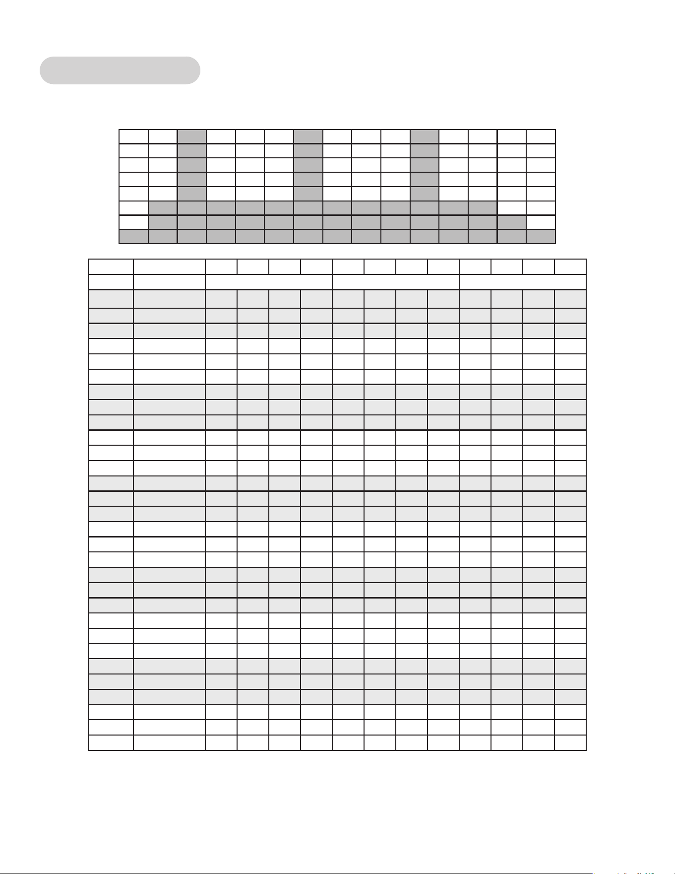
90
Cybex Owner’s Manual
Strength - Interval
A repeating 15 second high intensity spike promotes strength gains
Time :30 :30 :30 :30 1:00 1:00 1:00 1:00 :30 :30 :30 :30
Level Warm Up Core Cool Down
10 Resistance 25 30 40 45 100 35 35 35 30 25 20 15
10 Incline 6 12 16 18 20 20 20 20 6 6 6 6
10 Target Pace 100 100 100 100 120 80 80 80 100 100 100 100
9 Resistance 25 30 35 40 95 35 35 35 30 25 20 15
9 Incline 6 12 16 18 20 20 20 20 6 6 6 6
9 Target Pace 100 100 100 100 120 80 80 80 100 100 100 100
8 Resistance 25 30 35 40 90 35 35 35 30 25 20 15
8 Incline 6 12 14 16 18 18 18 18 6 6 6 6
8 Target Pace 100 100 100 100 120 80 80 80 100 100 100 100
7 Resistance 25 30 35 40 85 30 30 30 25 20 20 15
7 Incline 6 12 14 16 18 18 18 18 6 6 6 6
7 Target Pace 100 100 100 100 120 80 80 80 100 100 100 100
6 Resistance 20 25 30 35 80 30 30 30 25 20 20 15
6 Incline 6 12 14 16 18 18 18 18 6 6 6 6
6 Target Pace 100 100 100 100 120 80 80 80 100 100 100 100
5 Resistance 20 25 30 35 75 30 30 30 25 20 15 10
5 Incline 6 10 12 14 16 16 16 16 6 6 6 6
5 Target Pace 100 100 100 100 120 80 80 80 100 100 100 100
4 Resistance 20 25 30 35 70 25 25 25 20 20 15 10
4 Incline 6 10 12 14 16 16 16 16 6 6 6 6
4 Target Pace 100 100 100 100 120 80 80 80 100 100 100 100
3 Resistance 20 20 25 30 65 25 25 25 20 20 15 10
3 Incline 6 10 12 14 16 16 16 16 6 6 6 6
3 Target Pace 100 100 100 100 120 80 80 80 100 100 100 100
2 Resistance 15 20 25 30 60 20 20 20 15 15 10 10
2 Incline 6 8 10 12 14 14 14 14 6 6 6 6
2 Target Pace 100 100 100 100 120 80 80 80 100 100 100 100
1 Resistance 15 15 20
25 55 20 20 20 15 15 10 10
1 Incline 6 8 10 12 14 14 14 14 6 6 6 6
1 Target Pace 100 100 100 100 120 80 80 80 100 100 100 100
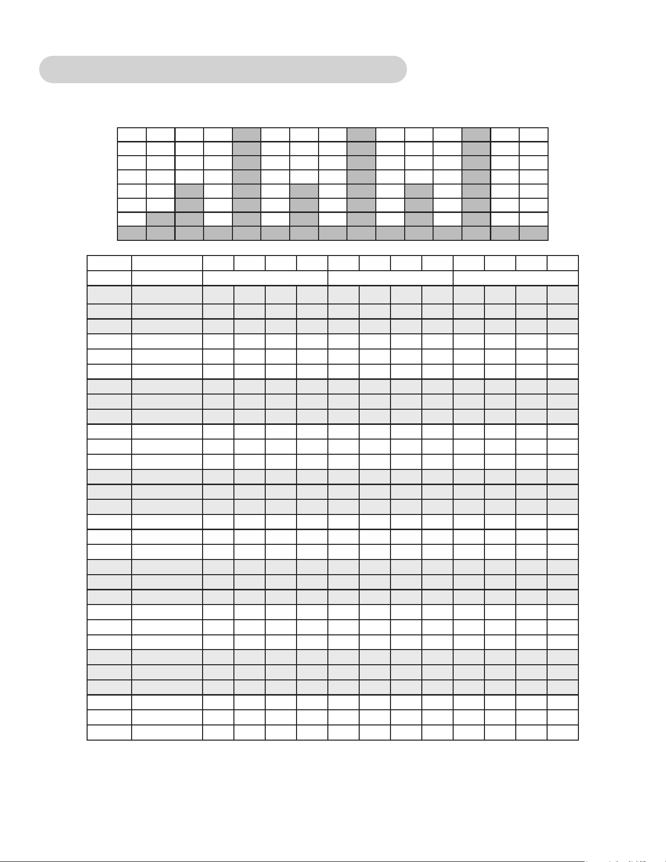
91
Cybex Owner’s Manual
Fitness (Mens) , Shaping (Womens) - Total Leg
Alternating levels of resistance and incline change the targeted muscle group in an interval format.
Time :30 :30 :30 :30 1:00 1:00 1:00 1:00 :30 :30 :30 :30
Level Warm Up Core Cool Down
10 Resistance 40 45 50 55 60 40 80 35 30 30 20 20
10 Incline 6 0 0 0 0 0 20 10 6 6 6 6
10 Target Pace 120 120 130 130 140 100 110 100 100 100 100 100
9 Resistance 35 40 45 50 55 35 75 30 25 25 20 20
9 Incline 6 0 0 0 0 0 20 10 6 6 6 6
9 Target Pace 120 120 130 130 140 100 110 100 100 100 100 100
8 Resistance 30 35 40 45 50 30 70 25 20 20 15 15
8 Incline 6 0 0 0 0 0 18 9 6 6 6 6
8 Target Pace 110 110 120 120 130 100 110 100 100 100 100 100
7 Resistance 25 30 35 40 45 25 65 20 15 15 10 10
7 Incline 0 0 0 0 0 0 18 9 6 6 6 6
7 Target Pace 110 110 120 120 130 100 110 100 100 100 100 100
6 Resistance 20 25 30 35 40 20 60 15 10 10 5 5
6 Incline 6 0 0 0 0 0 16 8 6 6 6 6
6 Target Pace 110 110 120 120 120 100 110 100 100 100 100 100
5 Resistance 15 20 25 30 35 15 55 10 5 5 0 0
5 Incline 6 0 0 0 0 0 14 8 6 6 6 6
5 Target Pace 100 100 110 110 110 100 110 100 100 100 100 100
4 Resistance 10 15 20 25 30 15 50 10 5 5 0 0
4 Incline 6 4 2 2 2 0 12 7 6 6 6 6
4 Target Pace 80 80 100 100 100 80 100 100 100 100 100 100
3 Resistance 5 10 15 20 25 15 30 10 5 5 0 0
3 Incline 6 4 2 2 2 0 10 7 6 6 6 6
3 Target Pace 80 80 100 100 100 80 100 100 100 100 100 100
2 Resistance 0 5 10 15 20 10 25 5 5 5 0 0
2 Incline 6 6 4 4 2 0 10 6 6 6 6 6
2 Target Pace 80 80 100 100 100 80 100 80 80 80 80 80
1 Resistance 0 0 5
10 15 10 20 5 5 5 0 0
1 Incline 6 6 4 4 2 0 8 6 6 6 6 6
1 Target Pace 80 80 100 100 100 80 100 80 80 80 80 80
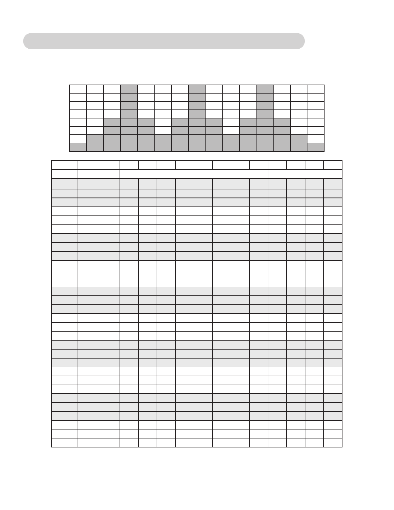
92
Cybex Owner’s Manual
Fitness (Mens) - Target: Hip, Shaping (Womens) - Glute Camp
2 minutes of progressive resistance and incline targeting the hip extensors are followed by a 1 minute
rest.
Time :30 :30 :30 :30 1:00 1:00 1:00 1:00 :30 :30 :30 :30
Level Warm Up Core Cool Down
10 Resistance 35 40 45 50 55 75 60 30 30 25 25 20
10 Incline 6 0 0 0 2 12 2 12 6 6 6 6
10 Target Pace 100 100 110 110 120 100 140 100 100 100 100 100
9 Resistance 30 35 40 45 50 70 55 25 25 20 20 15
9 Incline 6 0 0 0 2 12 2 12 6 6 6 6
9 Target Pace 100 100 110 110 120 100 140 100 100 100 100 100
8 Resistance 25 30 35 40 45 65 50 25 25 20 20 15
8 Incline 6 0 0 0 0 10 0 10 6 6 6 6
8 Target Pace 100 100 110 110 120 100 140 100 100 100 100 100
7 Resistance 20 25 30 35 40 60 45 20 20 15 15 10
7 Incline 6 0 0 0 0 10 0 10 6 6 6 6
7 Target Pace 100 100 110 110 120 100 140 100 100 100 100 100
6 Resistance 15 20 25 30 35 55 40 20 20 15 15 10
6 Incline 6 0 0 0 0 8 0 8 6 6 6 6
6 Target Pace 80 80 100 110 110 100 130 100 100 100 100 100
5 Resistance 10 15 20 25 30 50 35 15 15 10 10 5
5 Incline 6 0 0 0 0 8 0 8 6 6 6 6
5 Target Pace 80 80 100 110 110 100 130 80 80 80 80 80
4 Resistance 5 10 15 20 25 45 30 15 15 10 10 5
4 Incline 6 0 0 0 4 10 4 10 6 6 6 6
4 Target Pace 80 80 100 100 100 100 120 80 80 80 80 80
3 Resistance 0 5 10 15 20 40 25 15 15 10 10 5
3 Incline 6 0 0 0 4 10 4 10 6 6 6 6
3 Target Pace 80 80 100 100 100 100 120 80 80 80 80 80
2 Resistance 0 5 5 10 15 35 20 10 10 5 5 0
2 Incline 6 0 0 0 4 10 4 10 6 6 6 6
2 Target Pace 80 80 100 100 100 100 120 80 80 80 80 80
1 Resistance 0 0 5
5 10 30 15 5 5 5 0 0
1 Incline 6 0 0 0 4 10 4 10 6 6 6 6
1 Target Pace 80 80 100 100 100 100 120 80 80 80 80 80
93
Cybex Owner’s Manual
Cardio - Wave
A long duration interval promotes cardio endurance with enough rest to repeat the process.
Time :30 :30 :30 :30 1:00 1:00 1:00 1:00 :30 :30 :30 :30
Level Warm Up Core Cool Down
10 Resistance 30 35 40 45 45 75 35 25 25 25 20 20
10 Incline 6 14 16 16 18 20 12 6 6 6 6 6
10 Target Pace 80 100 110 120 120 120 140 100 100 100 80 80
9 Resistance 20 25 30 35 35 65 30 20 20 20 15 15
9 Incline 6 10 12 14 16 18 14 6 6 6 6 6
9 Target Pace 100 110 110 120 120 120 140 100 100 100 80 80
8 Resistance 20 20 25 30 30 55 25 15 15 15 10 10
8 Incline 6 8 10 12 14 16 12 4 6 6 6 6
8 Target Pace 100 110 110 120 120 120 140 100 100 100 80 80
7 Resistance 15 20 25 30 30 50 25 15 15 15 10 10
7 Incline 6 6 8 10 12 14 10 4 6 6 6 6
7 Target Pace 100 100 110 110 110 120 130 100 100 100 80 80
6 Resistance 15 15 20 25 25 40 20 15 15 15 10 10
6 Incline 6 4 6 8 10 12 8 2 6 6 6 6
6 Target Pace 100 100 110 110 110 110 130 100 100 100 80 80
5 Resistance 10 15 20 25 25 35 20 15 15 15 10 10
5 Incline 6 2 4 6 8 10 6 2 6 6 6 6
5 Target Pace 80 80 100 100 100 110 120 100 100 100 80 80
4 Resistance 10 10 15 20 20 25 15 10 10 10 5 5
4 Incline 6 2 4 4 6 8 4 0 6 6 6 6
4 Target Pace 80 80 100 100 100 110 120 80 80 80 80 80
3 Resistance 0 5 10 15 20 20 15 10 10 10 5 5
3 Incline 6 2 4 4 4 6 2 0 6 6 6 6
3 Target Pace 80 80 100 100 100 110 120 80 80 80 80 80
2 Resistance 0 0 5 10 15 10 10 5 5 5 5 5
2 Incline 6 0 2 2 2 4 0 0 6 6 6 6
2 Target Pace 80 80 100 100 100 100 110 80 80 80 80 80
1 Resistance 0 0 5
5 10 5 5 5 5 5 5 5
1 Incline 6 0 0 0 0 2 0 0 6 6 6 6
1 Target Pace 80 80 100 100 100 100 110 80 80 80 80 80
94
Cybex Owner’s Manual
Cardio - Interval
A 30 second charge improves aerobic power with 1 minute of recovery before a repeat.
Time :30 :30 :30 :30 1:00 1:00 1:00 :30 :30 :30 :30
Level Warm Up Core Cool Down
10 Resistance 35 45 55 65 70 45 45 40 35 30 20
10 Incline 6 10 12 12 14 14 14 6 6 6 6
10 Target Pace 120 130 140 140 140 110 110 110 110 100 100
9 Resistance 35 40 50 60 65 40 40 35 30 25 15
9 Incline 6 10 12 12 14 14 14 6 6 6 6
9 Target Pace 120 130 140 140 140 110 110 110 110 100 100
8 Resistance 30 40 50 55 60 35 35 30 25 20 15
8 Incline 6 8 10 10 12 12 12 6 6 6 6
8 Target Pace 110 120 130 130 130 110 110 110 110 100 100
7 Resistance 30 35 45 50 55 30 30 30 25 20 10
7 Incline 6 8 10 10 12 12 12 6 6 6 6
7 Target Pace 110 120 130 130 130 110 110 110 110 80 80
6 Resistance 25 35 40 45 50 30 30 30 25 20 10
6 Incline 6 6 8 8 10 10 10 6 6 6 6
6 Target Pace 100 110 120 120 120 100 100 100 110 80 80
5 Resistance 25 30 35 40 45 25 25 25 20 15 10
5 Incline 6 6 8 8 10 10 10 6 6 6 6
5 Target Pace 100 110 120 120 120 100 100 100 110 80 80
4 Resistance 20 25 30 35 40 25 25 25 20 15 10
4 Incline 6 4 6 6 8 8 8 6 6 6 6
4 Target Pace 80 100 110 110 110 100 100 100 80 80 80
3 Resistance 20 25 30 30 35 20 20 20 15 10 10
3 Incline 6 4 6 6 8 8 8 6 6 6 6
3 Target Pace 80 100 110 110 110 100 100 100 80 80 80
2 Resistance 15 20 25 25 30 20 20 20 15 10 5
2 Incline 6 2 4 4 6 6 6 6 6 6 6
2 Target Pace 80 80 100 100 100 100 100 100 80 80 80
1 Resistance 10 15 20 20 25 15 15 15 15 10 5
1 Incline 6 2 4 4 6 6 6 6 6 6 6
1 Target Pace 80 80 100 100 100
100 100 100 80 80 80

95
Cybex Owner’s Manual
Cardio - Heart Rate Control
Requires HR transmitter. The Arc will adapt the resistance as you maintain speed to keep your heart
rate at a certain level.
Power - Constant Power
You set the power in watts. Pedaling faster feels easier, pedaling slower feels harder; but the
workload remains the same.
Power - Adaptive Power
An ideal way to perform “live” interval training. You choose the level. The higher the level, the greater
the rate the resistance increases with speed.

10 Trotter Drive Medway, MA 02053
508-533-4300 • FAX 508-533-5183 • www.cybexintl.com