Loading ...
Loading ...
Loading ...
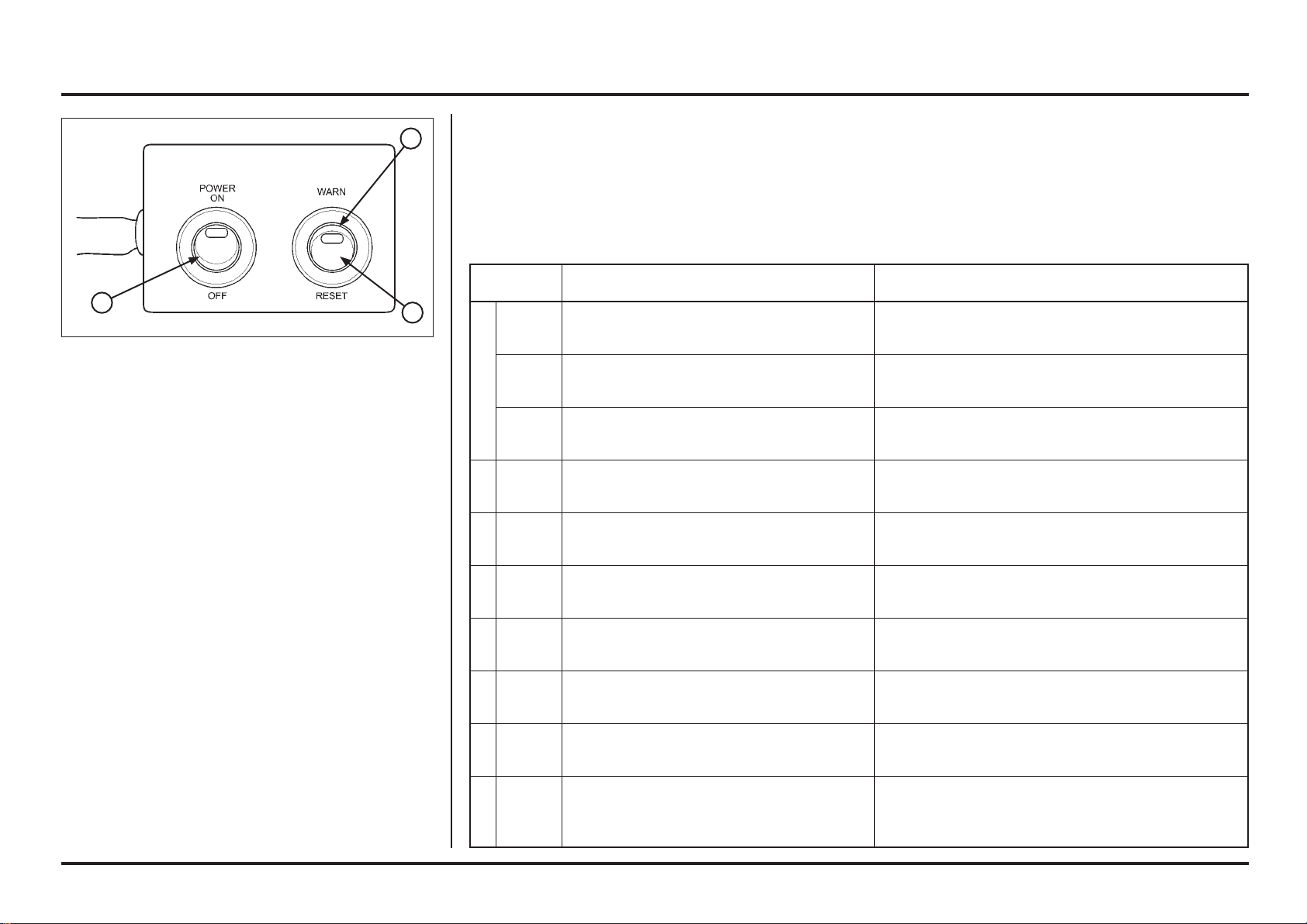
(1) POWER SWITCH
(2) MIL
(3) WARN/RESET SWITCH
Self-diagnosis Reset Procedure
– Connect the PGM-FI warning unit assembly to the wire
harness and 12 V battery same procedure as Self-diag-
nosis (see previous step).
– Before turn ON the power switch, turn the warning/
reset switch to the warning side.
– Turn the power switch ON, then turn the warning/reset
switch to reset side.
– The MIL lights about 5 seconds.
While the MIL lights, turn the warning/reset switch to
the warning side.
– Self-diagnosis memory data is erased, if the MIL turns
off and start blinking.
The “WARN/RESET” switch must be switched to
“WARN” side while the indicator lights. If not, the MIL
will not sart blinking
Note that the self-diagnosis memory data cannot be
erased if you disconnect the battery from the warning
unit assembly before the MIL starts blinking.
PGM-FI Self-diagnosis Malfunction Indicator Lamp
(MIL) Failure Codes
3
2
1
6-7
6-7
Electrical servicing
PGM-FI Self-diagnosis malfunction indicator lamp (MIL) failure codes
The PGM-FI MIL denotes the failure codes (the number of blinks from 0 to 54). When the indicator lights for 1.3
seconds, it is equivalent to ten blinks. For example; a 1.3 second illumination and two blinks (0.5 second x 2) of the
indicator equals 12 blinks. Follow code 12 troubleshooting.
When more than one failure occurs, the MIL shows the blinks in the order of lowest number to highest number. For
example; if the indicator blinks once, then seven times, two failures have occurred. Follow codes 1 and 7 troubles-
hooting.
Number of
blinks
Causes Symptoms
0No
blinks
Faulty ECM Engine does not start
No
blinks
Faulty ECM
(PGM-FI warning indicator output)
Engine operates normally
Stay lit Short circuit in service check connector
Faulty ECM
(PGM-FI warning indicator output)
Engine operates normally
1 Blink Open or short circuit in MAP sensor line
(in the ECM)
Faulty MAP sensor
Poor idle
7 Blinks Loose or poor contact on ECT sensor
Open or short circuit in ECT sensor wire
Faulty ECT sensor
Hard starting at a low temperature
(Simulate using numerical values; 90 ˚C/194˚F)
Cooling fan does not stop
8 Blinks Open or short circuit in TP sensor line
(in the ECM)
Faulty TP sensor
Poor engine response when operating the throttle
quickly
(Simulate using numerical values; throttle open 0˚)
9 Blinks Open or short circuit in IAT sensor line
(in the ECM)
Engine operates normally
(Simulate using numerical values; 25˚C/77˚F)
12 Blinks Loose or poor contact on injector connector
Open or short circuit in injector wire
Faulty injector
Engine does not start
21 Blinks Loose or poor contact on O2 sensor
Open or short circuit in O2 sensor wire
Faulty O2 sensor
Engine operates normally
54
Blinks Loose or poor contact on bank angle sensor
connector
Open circuit in bank angle sensor wire
Faulty bank angle sensor
Engine starts but stops after few seconds.
Loading ...
Loading ...
Loading ...