Loading ...
Loading ...
Loading ...
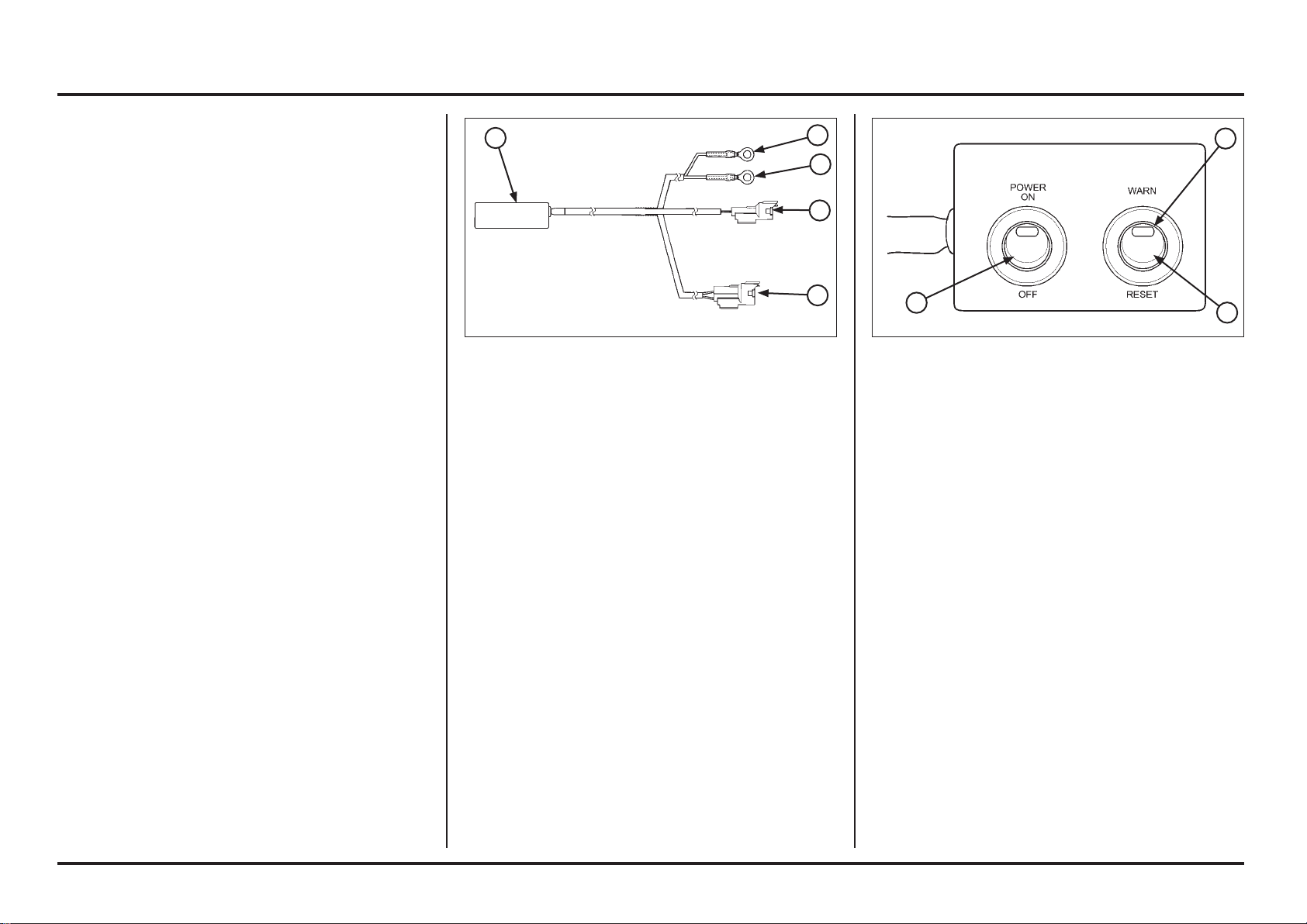
(1) PGM WARNING UNIT ASSEMBLY
(2) RED WIRE EYELET
(3) GREEN WIRE EYELET
(4) 2P (BLACK) CONNECTOR
(5) 4P (RED) CONNECTOR
DTC readout procedure
– Disconnect the fuel pump 2P (Black) connector.
– Disconnect the condenser 2P (Black) connector and
connect a warning unit connector to the wire harness
side.
Tool:
PGM-FI warning unit assembly 38890-NN4-306
– Make sure PGM-FI warning unit assembly power switch
is in OFF position.
– Connect the waring unit 4P (Red) connector to the ser-
vice check 4P (Red) connector.
– Connect the fully charged 12 V battery to the warning
unit terminals (red wire eyelet to the battery positive
terminal and green wire eyelet to the negative termi-
nal).
(1) POWER SWITCH
(2) MIL
(3) WARN/RESET SWITCH
PGM-FI
Self-diagnosis system
The PGM-FI system is equipped with the self-diagnostic
system. When any abnormality occurs in the system, the
ECM turns on the MIL and stores a DTC in its erasable
memory.
Fail-safe function
The PGM-FI system is provided with a fail-safe function to
secure a minimum running capability even when there is
trouble in the system. When any abnormality is detected
by the self-diagnosis function, running capability is main-
tained by pre-programmed value in the simulated program
map. When any abnormality is detected in the injector,
the fail-safe function stops the engine to protect it from
damage.
– Turn the PGM warning unit “WARN/RESET” switch to
the warning side as shown.
–
Turn the power switch ON, check that the MIL.
– If the ECM has no self diagnosis memory data, the MIL
will illuminate, when you turn the power switch ON.
– If the ECM has self diagnosis memory data, the MIL
will start blinking when you turn the power switch ON.
–
Note how many times the MIL blinks, and determine
the cause of the problem (page 6-7).
5
4
3
2
1
3
2
1
6-6
6-6
Electrical servicing
Loading ...
Loading ...
Loading ...