Loading ...
Loading ...
Loading ...
23En
English
adhesive tape around wiring that
comes into contact with metal
parts to protect the wiring.
– Place all cables away from moving
parts, such as the shift lever and
seat rails.
– Place all cables away from hot
places,
such as near the heater
outlet.
– Do not connect the yellow cable to
th
e battery by passing it through
the hole to the engine
compartment.
– Cover any disconnected cable
c
onnectors with insulating tape.
–Do not shorten any cables.
– Never cut the insulation of the
po
wer cable of this unit in order to
share the power with other devices.
The current capacity of the cable is
limited.
– Use a fuse of the rating prescribed.
– Never wire the negative speaker
cable
directly to ground.
– Never band together negative
cab
les of multiple speakers.
• W
hen this unit is on, control signals
are sent through the blue/white
cable. Connect this cable to the
system remote control of an external
power amp or the vehicle’s auto-
antenna relay control terminal (max.
300mA 12 V DC). If the vehicle is
equipped with a glass antenna,
connect it to the antenna booster
power supply terminal.
• Ne
ver connect the blue/white cable
to the power terminal of an external
power amp. Also, never connect it to
the power terminal of the auto
antenna. Doing so may result in
battery drain or a malfunction.
• Th
e graphical symbol placed
on the product means direct current.
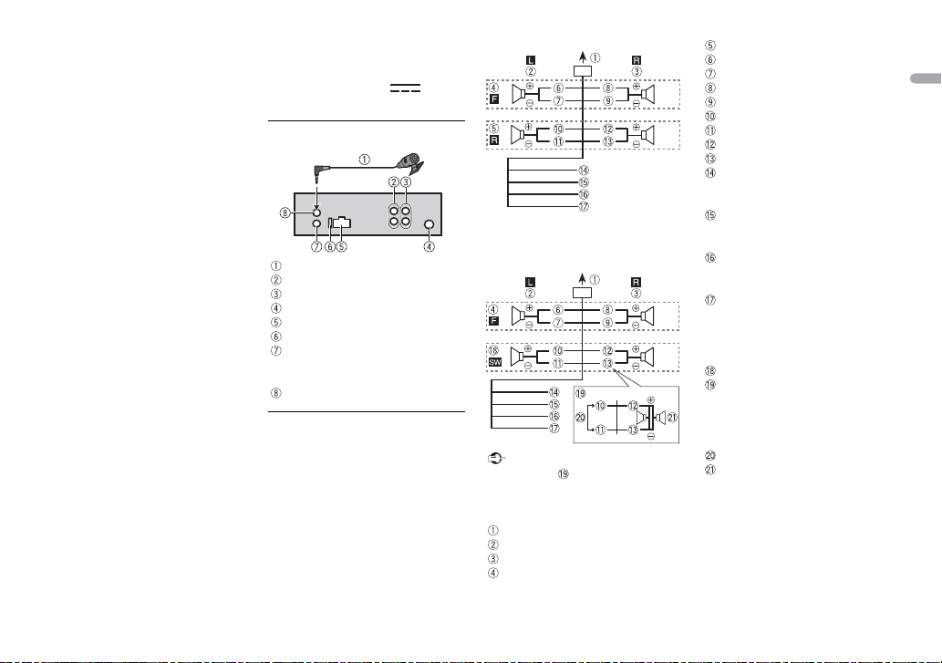
This unit
Microphone 3 m (9 ft. 10-1/8 in.)
Rear output or subwoofer output
Front output
Antenna input
Power cord input
Fuse (10 A)
Wired remote input
Hard-wired remote control adapter
can be
connected (sold separately).
Microphone input
Power cord
Perform these connections when not
connecting a rear speaker lead to a
subwoofer.
Perform these connections when
using a subwoofer without the
optional amplifier.
Important
In the case of above, two 4 Ω
subwoofers wired in parallel will
r
epresent a 2 Ω load.
To power cord input
Left
Right
Front speaker
Rear speaker
White
White/black
Gray
Gray/black
Green
Green/black
Violet
Violet/black
Black (chassis ground)
Connect to a clean, paint-free
me
tal location.
Yellow
Connect to the constant 12 V
s
upply terminal.
Red
Connect to terminal controlled by
t
he ignition switch (12 V DC).
Blue/white
Connect to the system control
t
erminal of the power amp or auto-
antenna relay control terminal
(max. 300 mA 12 V DC).
Subwoofer (4 Ω)
When using a subwoofer of 2 Ω, be
sure to connect the subwoofer to
t
he violet and violet/black leads of
this unit. Do not connect anything
to the green and green/black leads.
Not used.
Subwoofer (4 Ω) × 2
NOTE
Change the initial menu of this unit.
Refer to [SP-P/O MODE]
(page 7). The
subwoofer output of this unit is
mon
aural.
Loading ...
Loading ...
Loading ...