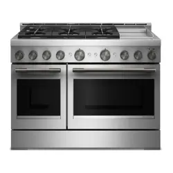
OWNER'S MANUAL for FREESTANDING GAS RANGE
FEATURE GUIDE
WARNING
Food Poisoning Hazard Do not let food sit in oven more than one hour before or after cooking. Doing so can result in food poisoning or sickness.
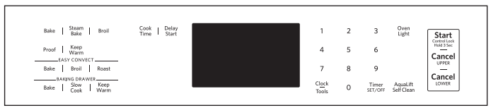
Electronic Oven Controls
Control Display
The aisplay will flash when powered up or after a power loss. Press CANCEL UPPER to clear. When the oven is not in use. the time of day is displayed. If the range is in Energy Save mode. the display will be blank when not in use.
Tones - Tones are audible signals. indicating the following:
One Tone
- Valid keypad press
- Oven is preheated (long tone)
- Function has been entered
- Reminder, repeating each minute after the end-of-cycle tones
Three Tones
Four Tones
Use the Clock/Tools keypad to change the tone settings.
Energy Save
The Energy Save mode puts the range into sleep mode and reduces energy consumption.
To Activate the Energy Save Mode:
1. Press and hold CLOCK/TOOLS for 3 seconds. “Energy saver on.’ will appear in the display.
2. The setting will be activated after 5 minutes.
To Deactivate the Energy Save Mode:
1. Press and hold CLOCK/TOOLS for 3 seconds. “Energy saver off” will appear in the display.
2. The clock will reappear in the display. and the range can be operated as usual.
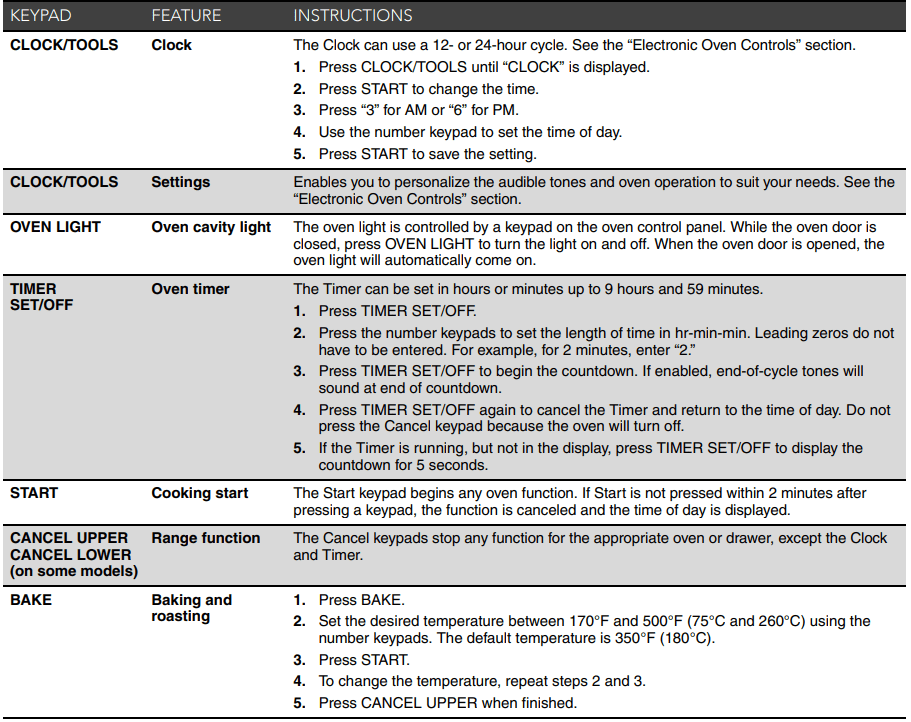
Settings
Many features of the oven control can be adjusted to meet your personal needs. These changes are made using the Clock/Tools keypad.
Use the Clock/Tools keypad to scroll through the features that can be changed. Each press of the Clock/Tools keypad will advance the display to the next setting. After selecting the feature to be changed. the control will prompt you for the required input. Then press START or CANCEL UPPER to exit and display the time of day. Details of all of the feature changes are explained in the following sections.
Press CANCEL UPPER to exit Settings.
Clock
- The Clock can use a 12- or 24-hour cycle.
- Press CLOCK/TOOLS until “CLOCK” is displayed.
- Press START to change the time.
- Press “3” for AM or “6” for PM.
- Use the number keypads to set the time of day.
- Press START or CANCEL UPPER to exit and display the time of day.
Fahrenheit and Celsius
The temperature is preset to Fahrenheit. but can be changed to Celsius.
- Press CLOCK/TOOLS until “TEMP UNIT” is displayed.
- The current setting will be displayed.
- Press the “1” keypad to adjust the setting.
- Press START or CANCEL UPPER to exit and display the time of day.
Audible Tones Disable
Turns off all tones. including the end of cycle tone and key press tones. Reminder tones are still active when all tones are disabled.
- Press CLOCK/TOOLS until “SOUND” is displayed.
- The current setting will be displayed.
- Press the “1” keypad to adjust the setting.
- Press START or CANCEL UPPER to exit and aisplay the time of day.
Sound Volume
Sets the volume of the tone to either high or low.
- Press CLOCK/TOOLS until “SOUND VOLUME” is displayed.
- The current setting will be displayed.
- Press the “1” keypad to adjust the setting.
- Press START or CANCEL UPPER to exit and display the time of day.
End of Cycle Tone
Activates or turns off the tones that sound at the end of a cycle.
- Press CLOCK/TOOLS until “END TONE” is displayed.
- The current setting will be displayed.
- Press the “1” keypad to adjust the setting.
- Press START or CANCEL UPPER to exit and display the time of day.
Key Press Tones
Activates or turns off the tones when a keypad is pressed.
- Press CLOCK/TOOLS until “KEYPRESS TONE” is displayed.
- The current setting will be displayed.
- Press the “1” keypad to adjust the setting.
- Prose START or CANCEL UPPER to exit and dleply theme of day.
Reminder Tones Disable
Turns off the short repeating tone that sounds every 1 minute after the end of cycle tones.
- Press CLOCK/TOOLS until “REMINDER TONE" is displayed.
- The current setting will be displayed.
- Press the “1” keypad to adjust the setting.
- Press START or CANCEL UPPER to exit and display the time of day.
12/24 Hour Clock
- Press CLOCK/TOOLS until “12/24 HOUR? is displayed.
- The current setting will be displayed.
- Press the “1” keypad to adjust the setting.
- Press START or CANCEL UPPER to exit and display the time of day.
Demo Mode
IMPORTANT: This feature is intended for use on the sales floor with 120 V power connection and permits the control features to be demonstrated without the oven turning on. If this feature is activated. the oven will not work.
- Press CLOCK/TOOLS until “DEMO MODE” is displayed.
- The current setting will be displayed.
- Press the “1” keypad to adjust the setting.
- Press START or CANCEL UPPER to exit and display the time of day.
Sabbath Mode
The Sabbath Mode sets the oven to remain on in a bake setting until turned off.
When the Sabbath Mode is set. only the Bake cycle will operate.
All other cooking and cleaning cycles are disabled. No tones will sound. and the displays will not indicate temperature changes.
When the oven door is opened or closed. the oven light will not turn on or off. and the heating elements will not turn on or off immediately.
To Enable Sabbath Mode Capability (One Time Only):
- Press CLOCK/TOOLS until “SABBATH?” is displayed.
- The current setting will be displayed.
- Press the “1” keypad to adjust the setting.
- Press START or CANCEL UPPER to exit and display the time of day.
12-Hour Shutoff
The oven control is set to automatically shut off the oven 12 hours after the oven initiates a cook or clean function. This will not interfere with any timed or delay cook functions.
- Press CLOCK/TOOLS until “12Hr AUTOOFF’ is displayed.
- The current setting will be displayed.
- Press the “1” keypad to adjust the setting.
- Press START or CANCEL UPPER to exit and display the time of day.
Languages - Scrolling Display Text
Language options are English. Spanish and French.
- Press CLOCK/TOOLS until “LANGUAGE” is displayed.
- The current setting will be displayed.
- Press the “1” or “2” keypad to select the desired language.
- Press START or CANCEL UPPER to exit and display the time of day.
Oven Temperature Offset Control
IMPORTANT: Do not use a thermometer to measure oven temperature. Elements will cycle on and off as needed to provide consistent temperature but may run slightly hot or cool at any point in time due to this cycling. Most thermometers are slow to react to temperature change and will not provide an accurate reading due to this cycling.
The oven provides accurate temperatures; however. it may cook faster or slower than your previous oven. so the temperature can be adjusted to personalize it for your cooking needs. It can be changed to Fahrenheit or Celsius.
To Adjust Oven Temperature:
1. Press CLOCK/TOOLS until “TEMP CALIB’ is displayed.
2. On some models. press “1” to adjust the drawer temperature calibration. Press START. wait 10 seconds for the display to change. and then continue with Step 3.
OR
Press START to adjust the oven temperature calibration. Wait 10 seconds for the display to change. and then continue with
Step 3.
3. Press the “3” keypad to increase the temperature in 5°F (3°C) increments. or press the “6” keypad to decrease the temperature in 5°F (3°C) increments. The offset range is from 30°F to +30°F (-18°C to +18°C).
4. Press START or CANCEL UPPER to exit and display the time of day.
RANGE MAINTENANCE AND CARE
Clean Cycle

AquaLift® Technology is an innovative cleaning solution that utilizes heat and water to release baked-on spills from the oven in less than 1 hour. This new cleaning technology is a low-heat, odor-free alternative to traditional self-cleaning options.
Allow the oven to cool to room temperature before using the Clean cycle. If your oven cavity is above 200°F (93°C), it will appear in the display, and the Clean cycle will not be activated until the oven cavity cools down.
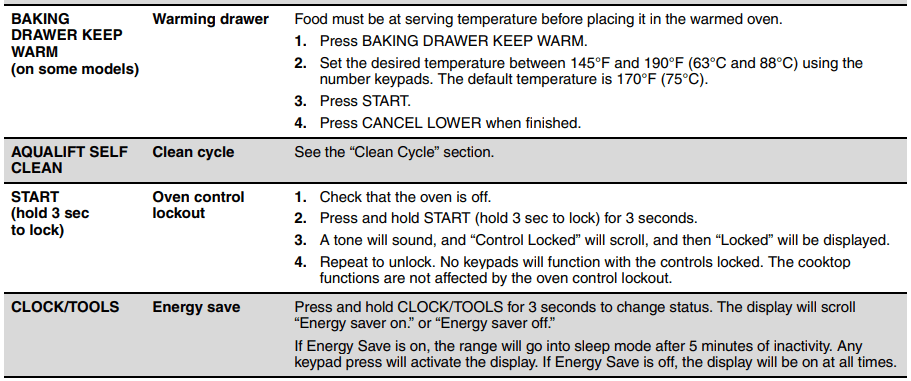
To Clean:
- Remove all racks and accessories from the oven cavity, and wipe excess soil. Use a plastic scraper to remove easily removed soils.
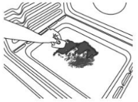
- Pour 13/4 cups (14 oz [414 mL]) of distilled or filtered water onto the bottom of the empty oven, and close the oven door.
- IMPORTANT: Do not use chemicals or other additives with the water. Do not open the oven door during the Clean cycle. The water on the oven bottom is hot.
- Press CLEAN/AQUALIFT SELF CLEAN and then STARTon the oven control panel.
- Allow 40 minutes for cleaning and cooldown. A beep will sound when the Clean cycle is complete.
- Press OFF/CANCEL/CANCEL UPPER at the end of the cycle. Off/Cancel/Cancel Upper may be pressed at any time to stop the Clean cycle.
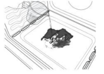
- Remove the residual water and loosened soils with a sponge or cloth immediately after the Clean cycle is complete. Much of the initial 13/4 cups (14 oz [414 mL]) of water will remain in the oven after the cycle is completed. If additional soils remain, leave a small amount of water in the oven bottom to assist with the cleaning.
- If any soils remain, remove them with a nonscratch scrubbing sponge or plastic scraper. Additional Clean cycles may be run to help remove the stubborn soils.
IMPORTANT: Do not use oven cleaners. The use of chemicals, including commercial oven cleaners or metal scouring pads, may cause permanent damage to the porcelain surface of the oven interior.
NOTE:
- The range should be level to ensure that the entire surface of the bottom of the oven cavity is covered by water at the beginning of the Clean cycle.
- For best results, use distilled or filtered water. Tap water may leave mineral deposits on the oven bottom.
- Before removing the residual water and loosened soils at the end of the Clean cycle, insert a cloth or paper towel between the lower edge of the oven door and the front frame to keep water from spilling onto the front of the range and the floor.
- Soil baked on through several cooking cycles will be more difficult to remove with the Clean cycle.
- Nonabrasive scrub sponges or eraser-style cleaning pads (without cleaners) can be effective for cleaning the oven cavity walls, oven door, and oven bottom for difficult soils. For best results, moisten the pads and sponges before use.
- Run an additional Clean cycle for stubborn soils
- Affresh® Kitchen Appliance Cleaner and affresh® Cooktop Cleaner may be used to clean the oven bottom, walls, and door when the oven has finished the cycle and returned to room temperature. If affresh® Cooktop Cleaner is used, it is recommended to wipe out the cavity with distilled water as well. Refer to the Quick Start Guide for ordering information.
General Cleaning
IMPORTANT: Before cleaning, make sure all controls are OFF and the oven and cooktop are cool. Always follow label instructions on cleaning products.
Soap, water, and a soft cloth or sponge are suggested first, unless otherwise noted.
EXTERIOR PORCELAIN ENAMEL SURFACES (on some models)
Food spills containing acids, such as vinegar and tomato, should be cleaned as soon as the entire range is cool. These spills may affect the finish.
Cleaning Method:
- Glass cleaner, mild liquid cleaner, or nonabrasive scrubbing pad: Gently clean around the model/serial/rating plate because scrubbing may remove numbers.
- Affresh® Kitchen and Appliance Cleaner Part Number W10355010 (not included):
See the Quick Start Guide for ordering information.
STAINLESS STEEL (on some models)
NOTE: To avoid damage to stainless steel surfaces, do not use soap-filled scouring pads, abrasive cleaners, Cooktop Cleaner, steel-wool pads, gritty washcloths, or abrasive paper towels.
Damage may occur to stainless steel surfaces, even with one-time or limited use.
Cleaning Method:
- Rub in direction of grain to avoid damaging.
- Affresh® Stainless Steel Cleaner Part Number W10355016 (not included):
See the Quick Start Guide for ordering information.
METALLIC PAINT (on some models)
Do not use abrasive cleaners, cleaners with bleach, rust removers, ammonia, or sodium hydroxide (lye) because paint surface may stain.
PORCELAIN-COATED GRATES AND CAPS
- Food spills containing acids, such as vinegar and tomato, should be cleaned as soon as the cooktop, grates and caps are cool. These spills may affect the finish.
- To avoid chipping, do not bang grates, and caps against each other or hard surfaces such as cast iron cookware.
- Do not reassemble caps on burners while wet. Do not clean in the Self-Cleaning cycle.
Cleaning Method:
- Nonabrasive plastic scrubbing pad and mildly abrasive cleanser: Clean as soon as cooktop, grates, and caps are cool.
- Dishwasher (grates only, not caps):
Use the most-aggressive cycle. Cooked-on soils should be soaked or scrubbed before going into a dishwasher.
Although the burner grates are durable, they may lose their shine and/or discolor when washed in a dishwasher.
- Gas Grate and Drip Pan Cleaner Part Number 31617 (not included):
See the Quick Start Guide for ordering information.
SURFACE BURNERS
- Food spills containing acids, such as vinegar and tomato, should be cleaned as soon as the cooktop, grates, and caps are cool. These spills may affect the finish.
- To avoid chipping, do not bang grates and caps against each other or hard surfaces such as cast iron cookware.
- Do not reassemble caps on burners while wet.
- Do not clean in the Self-Cleaning cycle.
- Do not clean in dishwasher.
Cleaning Method:
- Nonabrasive plastic scrubbing pad and mildly abrasive cleanser: Clean as soon as cooktop, grates, burners, and caps are cool.
- Gas Grate and Drip Pan Cleaner (not included).
COOKTOP CONTROLS
To avoid damage to the cooktop controls, do not use steel wool, abrasive cleansers, or oven cleaner.
To avoid damage, do not soak knobs. When replacing knobs, make sure knobs are in the Off position.
On some models, do not remove seals under knobs.
Cleaning Method:
- Soap and water: Pull knobs straight away from control panel to remove
GRIDDLE (on some models)
- To avoid damaging the nonstick surface, do not use steel wool or abrasive cleaners.
Cleaning Method:
- Mild detergent
- Dishwasher: Although the griddle is durable, it may lose its shine and/or is color when washed in a dishwasher.
CONTROL PANEL AND OVEN DOOR EXTERIOR
To avoid damage to the control panel, do not use abrasive cleaners, steel-wool pads, gritty washcloths, or abrasive paper towels.
Cleaning Method:
- Glass cleaner and soft cloth or sponge: Apply glass cleaner to soft cloth or sponge, not directly on panel.
- Affresh® Kitchen and Appliance Cleaner Part Number W10355010 (not included):
See the Quick Start Guide for ordering information.
OVEN RACKS
Cleaning Method:
- Steel-wool pad
- For racks that have discolored and are harder to slide, a light coating of vegetable oil applied to the rack guides will help them slide.
- Dishwasher (steam rack water reservoir only, not racks): Although the water reservoir is durable, it may lose its shine and/or discolor when washed in a dishwasher.
STORAGE/WARMING DRAWER (on some models)
Check that storage/warming drawer is cool and empty before cleaning.
Cleaning Method:
OVEN CAVITY
Use AquaLift® Technology regularly to clean oven spills.
Do not use oven cleaners.
Food spills should be cleaned when oven cools. At high temperatures, foods react with porcelain. Staining, etching, pitting, or faint white spots can result.
Cleaning Method:
- Self-Cleaning cycle: See the “Self-Cleaning Cycle” or “Clean Cycle” section first.
INSTALLATION INSTRUCTIONS REQUIREMENTS
Location Requirements
IMPORTANT: Observe all governing codes and ordinances. Do not obstruct flow of combustion and ventilation air.
- It is the installer’s responsibility to comply with installation clearances specified on the model/serial/rating plate. The model/serial/rating plate is located behind the oven door on the top right/left-hand side of the oven frame.
- The range should be located for convenient use in the kitchen.
- Recessed installations must provide complete enclosure of the sides and rear of the range.
- All openings in the wall or floor where range is to be installed must be sealed.
- Cabinet opening dimensions that are shown must be used. Given dimensions are minimum clearances.
- The anti-tip bracket must be installed. To install the anti-tip bracket shipped with the range, see "Install Anti-Tip Bracket" section.
- Grounded electrical supply is required. See "Electrical Requirements" section.
- Proper gas supply connection must be available. See "Gas Supply Requirements" section.
- Contact a qualified floor covering installer to check that the floor covering can withstand at least 200°F (93°C).
- Use an insulated pad or 1/4" (6.35 mm) plywood under range if installing range over carpeting.
IMPORTANT: To avoid damage to your cabinets, check with your builder or cabinet supplier to make sure that the materials used will not discolor, delaminate or sustain other damage. This oven has been designed in accordance with the requirements of UL and CSA International and complies with the maximum allowable wood cabinet temperatures of 194°F (90°C).
Cabinet Dimensions
Cabinet opening dimensions shown are for 25" (64.0 cm) countertop depth, 24" (61.0 cm) base cabinet depth and 36" (91.4 cm) countertop height.
IMPORTANT: If installing a range hood or microwave hood combination above the range, follow the range hood or microwave hood combination installation instructions for dimensional clearances above the cooktop surface.
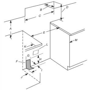
A. 18" (45.7 cm) upper side cabinet to countertop
B. 13" (33 cm) max. upper cabinet depth
C. 30" (76.2 cm) min. opening width
D. For minimum clearance to top of cooktop, see NOTE*.
E. In U.S.A.: 30¹⁄8" (76.5 cm) min. opening width
F. The shaded areas are recommended for installation of rigid gas pipe.
G. 11" (27.9 cm)
H. 17" (43.2 cm)
I. 2" (5.1 cm)
J. 4¹⁄2" (11.4 cm)
K. 3" (7.6 cm) min. clearance from both sides of range to side wall or
other combustible material.
L. Grounded outlet
M. Cabinet door or hinges should not extend into the cutout.
*NOTE: 24" (61.0 cm) minimum when bottom of wood or metal cabinet is covered by not less than 1/4" (6.4 mm) flame retardant millboard covered with not less than No. 28 MSG sheet steel, 0.015" (0.4 mm) stainless steel, 0.024" (0.6 mm) aluminum or 0.020" (0.5 mm) copper. 30" (76.2 cm) minimum clearance between the top of the cooking platform and the bottom of an uncovered wood or metal cabinet.
Gas Supply Requirements
Observe all governing codes and ordinances.
IMPORTANT:This installation must conform with all local codes and ordinances. In the absence of local codes, installation must conform with American National Standard, National Fuel Gas Code ANSI Z223.1 - latest edition or CAN/CGA B149 - latest edition.
IMPORTANT: Leak testing of the range must be conducted according to the manufacturer’s instructions.
Type of Gas
Natural Gas:
- This range is factory set for use with Natural gas. See “Gas Conversions” section. The model/serial rating plate located on the oven frame behind of the oven door has information on the types of gas that can be used. If the types of gas listed do not include the type of gas available, check with the local gas supplier.
Propane Gas Conversion:
- Conversion must be done by a qualified service technician.
- No attempt shall be made to convert the appliance from the gas specified on the model/serial rating plate for use with a different gas without consulting the serving gas supplier. See “Gas Conversions” section.
Gas Supply Line
- Provide a gas supply line of 3/4" (1.9 cm) rigid pipe to the range location. A smaller size pipe on longer runs may result in insufficient gas supply. With Propane gas, piping or tubing size can be 1/2" (1.3 cm) minimum. Usually, Propane gas suppliers determine the size and materials used in the system.
- NOTE: Pipe-joint compounds that resist the action of Propane gas must be used. Do not use TEFLON®† tape.
Flexible Metal Appliance Connector:
- If local codes permit, a new CSA design-certified, 4 to 5 ft (122 to 152.4 cm) long, 1/2" (13 mm) or 3/4" (19 mm) I.D., flexible metal appliance connector may be used for connecting range to the gas supply line.
- A 1/2" (13 mm) male pipe thread is needed for connection to the female pipe threads of the inlet to the appliance pressure regulator.
- Do not kink or damage the flexible metal tubing when moving the range.
- Must include a shut-off valve: Install a manual gas line shut-off valve in an easily accessible location. Do not block access to shut-off valve. The valve is for turning on or shutting off gas to the cooktop.
INSTALLATION
Unpack Range
- Remove shipping materials, tape and film from range.
- Remove oven racks and parts package from inside oven.
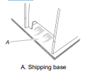
- Do not remove the shipping base at this time.
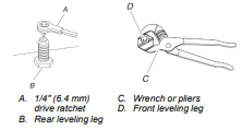
- On Ranges Equipped with a Storage Drawer:
Remove the storage drawer. See the “Storage Drawer” section. Use a 1/4" (6.4 mm) drive ratchet to lower the rear leveling legs one-half turn. Use a wrench or pliers to lower front leveling legs one-half turn.
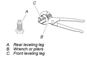
- On Ranges Equipped with a Warming Drawer or Premium Storage Drawer:
On ranges equipped with a warming drawer or premium storage drawer, the rear legs cannot be accessed by removing the warming drawer or premium storage drawer. It will be necessary to adjust the rear legs from outside the range. Use wrench or pliers to lower the front and rear leveling legs onehalf turn.
Install Anti-Tip Bracket
- Remove the anti-tip bracket from where it is taped inside the storage drawer, warming drawer, or premium storage drawer
- Determine which mounting method to use: floor or wall. If you have a stone or masonry floor, you can use the wall mounting method. If you are installing the range in a mobile home, you must secure the range to the floor.
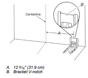
- Determine and mark centerline of the cutout space. The mounting can be installed on either the left side or right side of the cutout. Position mounting bracket against the wall in the cutout so that the V-notch of the bracket is 12 9⁄16" (31.9 cm) from centerline as shown.
- Drill two 1/8" (3 mm) holes that correspond to the bracket holes of the determined mounting method. See the following illustrations
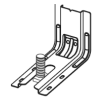
Floor Mounting
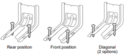
Wall Mounting
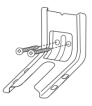
- Using the Phillips screwdriver, mount anti-tip bracket to the wall or floor with the two #12 x 15 ⁄8" (4.1 cm) screws provided, mount anti-tip bracket to the wall or floor.
- Move range close enough to opening to allow for final gas and electrical connections. Remove shipping base, cardboard or hardboard from under range.
- Move range into its final location, making sure rear leveling leg slides into anti-tip bracket.
- . Move range forward onto shipping base, cardboard or hardboard to continue installing the range using the following installation instructions.
Make Gas Connection
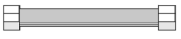
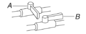
Typical flexible connection
- Apply pipe-joint compound made for use with propane gas to the smaller thread ends of the flexible connector adapters (see B and G in the following illustration).
- Attach one adapter to the gas pressure regulator and the other adapter to the gas shut-off valve. Tighten both adapters, being certain not to move or turn the gas pressure regulator.
- Use a 15/16" (2.4 cm) combination wrench and an adjustable wrench to attach the flexible connector to the adapters. IMPORTANT: All connections must be wrench-tightened. Do not make connections to the gas regulator too tight. Making the connections too tight may crack the regulator and cause a gas leak. Do not allow the regulator to turn when tightening fittings.
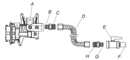
A. Gas pressure regulator
B. Use pipe-joint compound.
C. Adapter (must have 1/2" (1.3 cm) male pipe thread
D. Flexible connector
E. Manual gas shutoff valve
F. 1/2" (1.3 cm) or 3/4" (1.9 cm) gas pipe
G. Use pipe-joint compound.
H. Adapter
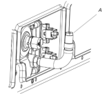
Complete Connection
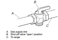
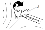
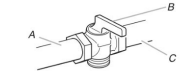
- Check that the gas pressure regulator shut-off valve is in the “on” position.
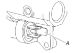
A. Gas pressure regulator shut-off valve shown in the “on” position.
- Open the manual shut-off valve in the gas supply line. The valve is open when the handle is parallel to the gas pipe.
A. Closed valve
B. Open valve
- Test all connections by brushing on an approved noncorrosive leak-detection solution. If bubbles appear, a leak is indicated. Correct any leak found.
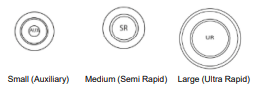
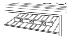
- Remove cooktop burner caps and grates from parts package. Place the burner bases as indicated by the following illustration for your model:
For Model KFGG504KPS
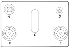
A. Medium (Semi Rapid)
B. Large (Ultra Rapid)
C. Oval (OV)
D. Small (Auxiliary)
E. Large (Ultra Rapid)
- Burner caps should be level when properly positioned. If burner caps are not properly positioned, surface burners will not light. Place burner grates over burners and caps
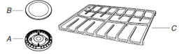
A. Burner base
B. Burner cap
C. Burner grate
Alignment: Be sure to align the gas tube opening in the burner base with the orifice holder on the cooktop and the igniter electrode with the notch in the burner base.
- Place the burner caps on the appropriate burner bases. IMPORTANT: The bottom of the small and medium caps are different. Do not put the wrong size burner cap on the burner base.
- Plug into a grounded 3-prong outlet.
- Slide range into final location, making sure the rear leveling leg slides into the slot of the anti-tip bracket.
Verify Anti-Tip Bracket Is Installed and Engaged
On Ranges Equipped with a Storage Drawer:
- Remove the storage drawer. See the “Storage Drawer” section.
- Use a flashlight to look underneath the bottom of the range.
- Visually check that the rear range foot is inserted into the slot of the anti-tip bracket.
On Ranges Equipped with a Warming Drawer or Premium Storage Drawer:
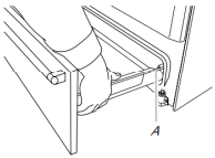
- Place the outside of your foot against the bottom front of the warming drawer or premium storage drawer, and grasp the lower right or left side of the control panel as shown. NOTE: If your countertop is mounted with a backsplash, it may be necessary to grasp the range higher than is shown in the illustration.
- Slowly attempt to tilt the range forward. If you encounter immediate resistance, the range foot is engaged in the anti-tip bracket.
- If the rear of the range lifts more than ½” (1.3 cm) off the floor without resistance, stop tilting the range and lower it gently back to the floor. The range foot is not engaged in the anti-tip bracket. IMPORTANT: If there is a snapping or popping sound when lifting the range, the range may not be fully engaged in the bracket. Check to see if there are obstructions keeping the range from sliding to the wall or keeping the range foot from sliding into the bracket. Verify that the bracket is held securely in place by the mounting screws.
- Slide the range forward, and verify that the anti-tip bracket is securely attached to the floor or wall.
- Slide range back so the rear range foot is inserted into the slot of the anti-tip bracket.
IMPORTANT: If the back of the range is more than 2” (5.1 cm) from the mounting wall, the rear range foot may not engage the bracket. Slide the range forward and determine if there is an obstruction between the range and the mounting wall. Changes to the gas supply must be performed by a qualified service technician. If you need assistance or service, refer to the Quick Start Guide for contact information.
- Repeat steps 1 and 2 to ensure that the range foot is engaged in the anti-tip bracket. If the rear of the range lifts more than ½” (1.3 cm) off the floor without resistance, the anti-tip bracket may not be installed correctly. Do not operate the range without anti-tip bracket installed and engaged. If you need assistance or service, refer to the Quick Start Guide for contact information.
Level Range
Determine if you have AquaLift® Technology or Steam Clean by referring to the “Range Maintenance and Care” section.
For Ranges with AquaLift® Technology or Steam Clean:
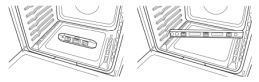
- Place level on the oven bottom as indicated in one of the two figures below depending on the size of the level. Check with the level side to side and front to back.
- If range is not level, pull range forward until rear leveling leg is removed from the anti-tip bracket.
- Follow the directions in Style 1 or Style 2, depending on the style of drawer supplied with the range.
For Ranges without AquaLift® Technology or Steam Clean:
- Place a standard flat rack in oven.
- Place level on the rack and check levelness of the range, first side to side; then front to back.
- If range is not level, pull range forward until rear leveling leg is removed from the anti-tip bracket.
- Follow the directions in Style 1 or Style 2, depending on the style of drawer supplied with the range.
Style 1: Ranges Equipped with a Storage Drawer:
- Use a 1/4" (6.4 mm) drive ratchet, wrench or pliers to adjust leveling legs up or down until the range is level. Push range back into position. Check that rear leveling leg is engaged in the anti-tip bracket.
Style 2: Ranges Equipped with a Warming Drawer or Premium Storage Drawer:
- Use a wrench or pliers to adjust leveling legs up or down until the range is level. Push range back into position. Check that rear leveling leg is engaged in the anti-tip bracket.
- NOTE: Range must be level for satisfactory baking performance and best cleaning results using AquaLift® Technology and Steam Clean functions.
Electronic Ignition System
Initial Lighting and Gas Flame Adjustments
Cooktop and oven burners use electronic igniters in place of standing pilots. When the cooktop control knob is turned to the “LITE” position, the system creates a spark to light the burner. This sparking continues, as long as the control knob is turned to “LITE.”
When the oven control is turned to the desired setting, sparking occurs and ignites the gas.
Check Operation of Cooktop Burners
Standard Surface Burners
Push in and turn each control knob to the “LITE” position.
The flame should light within 4 seconds. The first time a burner is lit, it may take longer than 4 seconds to light because of air in the gas line.
If Burners Do Not Light Properly:
- Turn cooktop control knob to the “OFF” position.
- Check that the range is plugged in. Check that the circuit breaker has not tripped or the household fuse has not blown.
- Check that the gas shutoff valves are set to the “open” position.
- Check that burner caps are properly positioned on burner bases.
Repeat start-up. If a burner does not light at this point, turn the control knobs to the “OFF” position and contact your dealer or authorized service company for assistance.
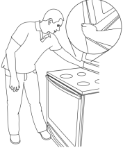
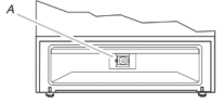
Check Operation of Oven Bake Burner
- Remove the oven rack.
- To remove the oven bottom: Remove 2 screws at the rear of the oven bottom. Lift the rear of the oven bottom up and back until the front of the panel is away from the front frame. Remove it from oven and place on a covered surface.
A. Screws
B. Oven bottom
- You can check the burner flame by using a mirror. Insert a mirror to one side of the burner. Look into the mirror to check flame.
- Push the BAKE pad.
- Press the START pad.
The oven bake burner should light within 8 seconds. Under certain conditions, it may take the burner up to 50 to 60 seconds to light.
Electronic igniters are used to light the bake and broil burners.
Refer to the Quick Start Guide and online Control Guide for proper operation of the oven controls.
Adjust Flame Height
Adjust the height of top burner flames. The cooktop “low” burner flame should be a steady blue flame approximately 3/8" (9.5 mm) high.
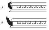
A. Low flame
B. High flame
To adjust standard burner:
The flame can be adjusted using the adjustment screw in the center of the valve stem. The valve stem is located directly underneath the control knob.
If the “low” flame needs to be adjusted:
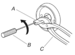
A. Control knob stem
B. Screwdriver
C. Pliers
- Light 1 burner and turn to lowest setting.
- Remove the control knob. Hold the knob stem with a pair of pliers. Use a small flat blade screwdriver to turn the screw located in the center of the control knob stem until the flame is the proper size.
- Replace the control knob.
- Test the flame by turning the control from “LO” to “HI,” checking the flame at each setting and ensuring there is a steady flame.
- Repeat the previous steps for each burner.
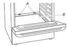
Adjust Oven Bake Burner Flame (if needed)
- On models with a warming drawer, remove access cover plate (1 screw) located at the back of the warming drawer compartment.
- Check the oven bake burner for proper flame. This flame should have a ½" (1.3 cm) long inner cone of bluish-green, with an outer mantle of dark blue, and should be clean and soft in character. No yellow tips, blowing or lifting of flame should occur.
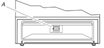
- If the oven bake flame needs to be adjusted, locate the air shutter near the center rear of the range. Loosen the locking screw and rotate the air shutter until the proper flame appears. Tighten locking screw.
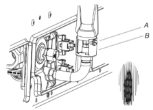
A. Locking screw
B. Air shutter
- Push CANCEL/OFF when finished.
- Reinstall flame spreader and oven bake burner cover.
Warming Drawer or Premium Storage Drawer (on some models)
Remove all items from inside the baking drawer, warming drawer or premium storage drawer, and then allow the range to cool completely before attempting to remove the drawer.
To Remove:
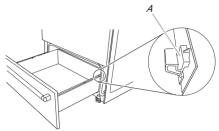
- Open the drawer to its fully open position.
- Using a flat-blade screwdriver, gently loosen the drawer from the glide alignment notch, and then lift up the drawer alignment tab from the glide.
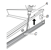
A. Flat-blade screwdriver
B. Drawer alignment tab
C. Drawer glide notch
- Repeat Step 2 on the other side. The drawer is no longer attached to the drawer glides. Using both hands, pick up the drawer to complete the removal.
To Replace:
- Align the forward drawer notches with the notches in the drawer glides on both sides. Place the rear alignment tabs into the drawer glides on both sides.
A. Drawer alignment tab
B. Drawer glide notch
- Push the warming drawer or premium storage drawer in all the way.
- Gently open and close the warming drawer or premium storage drawer to ensure it is seated properly on the glides on both sides
Storage Drawer (on some models)
The storage drawer can be removed. Before removing, make sure drawer is cool and empty.
To Remove:
- Pull the storage drawer straight back to the drawer stop.
A. Drawer stop notch
- Lift up the front of the drawer and pull the drawer out
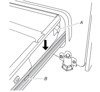
To Replace:
- Lift up the front of the drawer and place the rear of the drawer inside the range so that the drawer stop notch is behind the drawer glide.
- Lower the drawer so that the edge of the slide rail drops into the slot in the drawer glide.
- Slowly push the drawer into the range.
A. Engage drawer glide
NOTE: When properly installed, the rear slides on the bottom of the drawer will engage the base rails and the drawer will not tip when items are placed in the drawer.
Oven Door
For normal range use, it is not suggested to remove the oven door. However, if removal is necessary, make sure the oven is OFF and cool. Then, follow these instructions. The oven door is heavy.
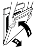
To Remove:
- Open oven door all the way.
- Pinch the hinge latch between two fingers and pull forward. Repeat on other side of oven door.
A. Hinge Latch
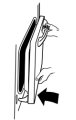
- Close the oven door as far as it will shut.
- Lift the oven door while holding both sides. Continue to push the oven door closed and pull it away from the oven door frame.
To Replace:
- Insert both hanger arms into the door
- Open the oven door. You should hear a click as the door is set into place.
- Move the hinge levers back to the locked position. Check that the door is free to open and close. If it is not, repeat the removal and installation procedures.
Complete Installation
- Check that all parts are now installed. If there is an extra part, go back through the steps to see which step was skipped.
- Check that you have all of your tools.
- Dispose of/recycle all packaging materials.
- Check that the range is level. See the “Level Range” section.
- Use a mild solution of liquid household cleaner and warm water to remove waxy residue caused by shipping material. Dry thoroughly with a soft cloth. For more information, read the “Range Maintenance and Care” section.
- Read the Quick Start Guide and online Control Guide.
- Turn on surface burners and oven. See the Quick Start Guide and online Control Guide for specific instruction on range operation.
If Range Does Not Operate, Check the Following:
Household fuse is intact and tight; or circuit breaker has not tripped.
Range is plugged into a grounded 3-prong outlet.
Gas pressure regulator shutoff valve is in the “on” position.
Electrical supply is connected.
See the online “Troubleshooting” section.
- When the range has been on for 5 minutes, check for heat. If the range is cold, turn off the range and check that the gas supply line shut-off valve is open.
If the gas supply line shut-off valve is closed, open it, and then repeat the 5-minute test as outlined above.
If the gas supply line shutoff valve is open, press the CANCEL button on the oven control panel and contact a qualified technician.
GAS CONVERSIONS
Gas conversions from Natural gas to propane gas or from propane gas to Natural gas must be done by a qualified installer.
Propane Gas Conversion
- Turn manual shutoff valve to the closed position.
A. To range
B. Manual shut-off valve closed position
C. Gas supply line
- Unplug range or disconnect power
To Convert Gas Pressure Regulator (Natural gas to Propane)
- Remove the premium storage drawer, warming drawer or baking drawer. See the “Remove/Replace Drawer”, “Storage Drawer” or “Warming Drawer or Premium Storage Drawer” section.
- Locate gas pressure regulator at rear of the drawer compartment. NOTE: On models with a warming drawer or baking drawer, an access cover must be removed to access the gas pressure regulator
A. Gas pressure regulator
IMPORTANT: Do not remove the gas pressure regulator
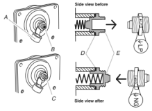
- Remove plastic cover from gas pressure regulator cap
- Turn gas pressure regulator cap counterclockwise with a 5/8" (1.6 cm) combination wrench to remove. NOTE: Do not remove the spring beneath the cap.
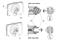
A. Plastic cover
B. Gas pressure regulator cap with solid end facing out
C. Gas pressure regulator cap with hollow end facing out
D. Washer
E. Gas pressure regulator cap
- Turn over the gas pressure regulator cap and reinstall on regulator so that the hollow end faces out and the marking “↓LP” is facing the direction shown in the above drawing.
- Replace plastic cover over gas pressure regulator cap.
To Convert Surface Burners (Natural Gas to Propane Gas)
- Remove burner cap.
- Remove the burner base.
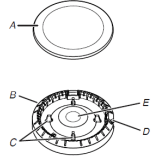
A. Burner cap
B. Burner base
C. Alignment pins
D. Igniter electrode
E. Gas tube opening
- Apply masking tape to the end of a 9/32" (7 mm) nut driver to help hold the gas orifice spud in the nut driver while changing it. Press nut driver down onto the gas orifice spud and remove by turning it counterclockwise and lifting out. Set gas orifice spud aside.
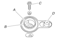
A. Orifice spud
B. Orifice spud holder
C. Screw
D. Spark electrode
- Gas orifice spuds are stamped with a number on the side or top. Replace the Natural gas orifice spud with the correct Propane gas orifice spud.

A. Stamped Number
Refer to the following chart for correct Propane gas orifice spud placement.
Propane Gas Orifice Spud Chart for Surface Burner
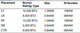
NOTE: Refer to the Model Number and Serial Number Plate located on the oven frame behind the top right side of the oven door for proper sizing of spuds for each burner location.
- Place Natural gas orifice spuds in the cardboard orifice spud holder.
- Replace the burner base.
- Replace burner cap.
- Repeat steps 1-7 for the remaining burners.
Natural Gas Conversion
To Convert Gas Pressure Regulator (Propane Gas to Natural Gas)
- Remove the premium storage drawer, warming drawer or baking drawer or premium storage drawer. See the Remove / Replace Drawer, Storage Drawer or Warming Drawer or Premium Storage Drawer section.
- Locate gas pressure regulator at rear of the drawer compartment. NOTE: On models with a warming drawer or baking drawer, an access cover must be removed to access the gas pressure regulator.
A. Gas pressure regulator
IMPORTANT: Do not remove the gas pressure regulator.
- Remove plastic cover from gas pressure regulator cap.
- Turn gas pressure regulator cap counterclockwise with a 5/8" (1.6 cm) combination wrench to remove. NOTE: Do not remove the spring beneath the cap.
A. Plastic cover
B. Gas pressure regulator cap with hollow end facing out
C. Gas pressure regulator cap with solid end facing out
D. Washer
E. Gas pressure regulator cap
- Turn over the gas pressure regulator cap and reinstall on regulator so that the solid end faces out and the marking “↓NG” is facing the direction shown in the above drawing.
- Replace plastic cover over gas pressure regulator cap.
To Convert Oven Bake Burner (Propane Gas to Natural Gas)
- Remove the oven racks.
- Remove two screws and washers at the rear of the oven bottom.
- Lift the rear of the oven bottom up and back until the front of the panel is away from the front frame. Remove from oven and set it aside on a covered surface.
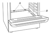
A. Screws
B. Oven bottom
- Remove 1 screw from the bake burner.
- Slide the front of the bake burner to the side to remove tab from front of oven. Lift the back of the bake burner off the oven orifice, and set the bake burner aside.
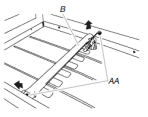
A. Screw
B. Bake burner
- Using a 3/8" (9.5 mm) nut driver or combination wrench, turn the Propane gas bake burner orifice spud counterclockwise to remove. The spud will be stamped with a "56."
- Replace the “56” spud with a “47” spud. Install the Natural gas bake burner orifice spud, turning it clockwise until snug. IMPORTANT: Do not overtighten.
A. Orifice spud
- Position the back of the bake burner over the oven orifice ,and then slide the tab on front of the bake burner into the front of the oven.
- Reattach the bake burner with 1 screw.
- Position the front of the oven bottom panel toward the frontframe, and then lower the rear of the oven bottom panel into the oven.
- Reattach the oven bottom panel with 2 screws.
Complete Installation (Propane Gas to Natural Gas)
1. Refer to the “Make Gas Connection” section for properly connecting the range to the gas supply.
2. Refer to the “Electronic Ignition System” section for proper burner ignition, operation and burner flame adjustments.
IMPORTANT: You may have to adjust the “LO” setting for each cooktop burner.
Checking for proper cooktop, bake and broil burner flame is very important. The small inner cone should have a very distinct blue flame 1/4" (0.64 cm) to 1/2" (1.3 cm) long. The outer cone is not as distinct as the inner cone. Propane gas flames have a slightly yellow tip.
3. Refer to “Complete Installation” in the “Installation
Instructions” section of this manual to complete this procedure.
NOTE: Make sure to save the orifices that have just been replaced in the conversion.