User manual Gas Range
RANGE MAINTENANCE AND CARE
General Cleaning
IMPORTANT: Before cleaning, make sure all controls are OFF and the oven and cooktop are cool. Always follow label instructions on cleaning products.
Soap, water, and a soft cloth or sponge are suggested first, unless otherwise noted.
EXTERIOR PORCELAIN ENAMEL SURFACES (on some models)
Food spills containing acids, such as vinegar and tomato, should be cleaned as soon as the entire range is cool. These spills may affect the finish.
Cleaning Method:
- Glass cleaner, mild liquid cleaner, or nonabrasive scrubbing pad: Gently clean around the model/serial/rating plate because scrubbing may remove numbers.
- Affresh®† Kitchen and Appliance Cleaner Part Number W10355010 (not included): See the Quick Start Guide for ordering information.
STAINLESS STEEL (on some models)
NOTE: To avoid damage to stainless steel surfaces, do not use soap-filled scouring pads, abrasive cleaners, Cooktop Cleaner, steel-wool pads, gritty washcloths, or abrasive paper towels. Damage may occur to stainless steel surfaces, even with one-time or limited use.
Cleaning Method:
- Rub in direction of grain to avoid damaging.
- Affresh® Stainless Steel Cleaner Part Number W10355016 (not included): See the Quick Start Guide for ordering information.
Yellow Heat Stains:
1. Add 1 tbs (15 mL) of table salt to 1/4 cup (59.1 mL) of vinegar, and then stir for 1 minute. Not all of the salt will dissolve.
2. Using a soft cloth, soak up the liquid of the vinegar mixture. Dab the wet cloth onto the yellow stains for 3 to 4 minutes. The wetter the stainless steel is, the better the cleaning results will be.
3. Let sit until the yellow stains have faded. Using a dry soft cloth, wipe off the remaining vinegar mixture.
4. Repeat steps 1 to 3 until all yellow stains have been removed.
5. Using clean water and a fresh soft cloth, clean off any remaining residue. Dry with a clean soft cloth.
6. Use affresh® Stainless Steel Cleaner Part Number W10355016 (not included) to protect and polish the cleaned surface.
NOTE: Remove surface grates before cleaning rear vent trim. Avoid dripping the vinegar mixture into the vent holes or down the back of the range.
METALLIC PAINT (on some models)
Do not use abrasive cleaners, cleaners with bleach, rust removers, ammonia, or sodium hydroxide (lye) because paint surface may stain.
PORCELAIN-COATED GRATES AND CAPS
Food spills containing acids, such as vinegar and tomato, should be cleaned as soon as the cooktop, grates and caps are cool. These spills may affect the finish.
To avoid chipping, do not bang grates, and caps against each other or hard surfaces such as cast iron cookware.
Do not reassemble caps on burners while wet. Do not clean in the Self-Cleaning cycle.
Cleaning Method:
- Nonabrasive plastic scrubbing pad and mildly abrasive cleanser: Clean as soon as cooktop, grates, and caps are cool.
- Dishwasher (grates only, not caps): Use the most-aggressive cycle. Cooked-on soils should be soaked or scrubbed before going into a dishwasher. Although the burner grates are durable, they may lose their shine and/or discolor when washed in a dishwasher.
- Gas Grate and Drip Pan Cleaner Part Number 31617 (not included): See the Quick Start Guide for ordering information.
COOKTOP CONTROLS
To avoid damage to the cooktop controls, do not use steel wool, abrasive cleansers, or oven cleaner.
To avoid damage, do not soak knobs. When replacing knobs, make sure knobs are in the Off position.
On some models, do not remove seals under knobs.
Cleaning Method:
- Soap and water: Pull knobs straight away from control panel to remove
GRIDDLE (on some models)
To avoid damaging the nonstick surface, do not use steel wool or abrasive cleaners.
Cleaning Method:
- Mild detergent
- Dishwasher: Although the griddle is durable, it may lose its shine and/or is color when washed in a dishwasher.
CONTROL PANEL AND OVEN DOOR EXTERIOR
To avoid damage to the control panel, do not use abrasive cleaners, steel-wool pads, gritty washcloths, or abrasive paper towels
Cleaning Method:
- Glass cleaner and soft cloth or sponge: Apply glass cleaner to soft cloth or sponge, not directly on panel.
- Affresh® Kitchen and Appliance Cleaner Part Number W10355010 (not included): See the Quick Start Guide for ordering information.
FEATURE GUIDE
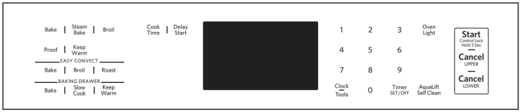
CLOCK/TOOLS
The Clock can use a 12- or 24-hour cycle. See the “Electronic Oven Controls” section.
1. Press CLOCK/TOOLS until “CLOCK” is displayed.
2. Use the number keypads to set the time of day.
3. Press START to change the time.
4. Press “3” for AM or “6” for PM.
Enables you to personalize the audible tones and oven operation to suit your needs.
See the “Electronic Oven Controls” section.
OVEN LIGHT
The oven light is controlled by a keypad on the oven control panel. While the oven door is closed, press OVEN LIGHT to turn the light On and Off. When the oven door is opened, the oven light will automatically come On.
TIMER SET/OFF
The Timer can be set in hours or minutes up to 9 hours and 59 minutes.
1. Press TIMER SET/OFF.
2. Press the number keypads to set the length of time in hr-min-min. Leading zeros do not have to be entered. For example, for 2 minutes, enter “2.”
3. Press TIMER SET/OFF to begin the countdown. If enabled, end-of-cycle tones will sound at end of countdown.
4. Press TIMER SET/OFF again to cancel the Timer and return to the time of day. Do not press the Cancel keypad because the oven will turn off.
5. If the Timer is running but not in the display, press TIMER SET/OFF to display the countdown for 5 seconds.
START
The Start keypad begins any oven function. If Start is not pressed within 2 minutes after pressing a keypad, the function is canceled and the time of day is displayed.
CANCEL UPPER CANCEL LOWER (on some models)
The Cancel keypad stops any function for the appropriate oven or drawer, except the Clock and Timer.
BAKE
1. Press BAKE.
2. Press the number keypads to set the desired temperature. If the temperature entered is not in the range of the temperatures allowed, the minimum or maximum allowed temperature will be displayed. Enter a temperature in the allowable range.
3. Press START.
4. To change the temperature, repeat steps 2 and 3.
5. Press CANCEL UPPER when finished.
STEAM BAKE
1. Insert the steam rack with water reservoir in the oven.
2. Pour 11 /2 cups (350 mL) of warm water into the water reservoir. NOTE: Do not fill past the MAX mark.
3. Press STEAM BAKE.
4. Press the number keypad to select the desired food option.
5. Press the number keypads to set the temperature.
6. Press START.
7. Insert food when preheating finishes.
8. (Optional) Press COOK TIME. Press the number keypads to set the cook time.
9. Press START.
10. Press CANCEL UPPER when finished.
NOTE: Let oven cool before removing and emptying water reservoir.
BROIL
1. Press BROIL.
2. Press the number keypads to set the desired temperature. If the temperature entered is not in the range of the temperatures allowed, the minimum or maximum allowed temperature will be displayed. Enter a temperature in the allowable range.
3. Press STARTand allow the oven to preheat for 2 minutes.
4. To change the temperature, repeat steps 2 and 3.
5. Position the cookware in the oven, and then close the door.
6. Press CANCEL UPPER when finished.
PROOF
1. Place prepared dough in oven. Press PROOF.
2. Press START. Let the dough rise until nearly doubled in size. Proofing time may vary depending on dough type and quantity.
3. Press CANCEL UPPER when finished proofing.
Refer to the “Proofing Bread” section for more information.
KEEP WARM
Food must be at serving temperature before placing it in the warmed oven.
1. Press KEEP WARM.
2. Press the number keypads to set the desired temperature. If the temperature entered is not in the range of the temperatures allowed, the minimum or maximum allowed temperature will be displayed. Enter a temperature in the allowable range.
3. Press START.
4. Press CANCEL UPPER when finished.
EASY CONVECT BAKE
1. Press EASY CONVECT BAKE.
2. Press “1” to have the oven automatically convert the temperature and time for convection baking. Press “2” to manually convert the temperature and time.
3. Press the number keypads to set the desired temperature. If the temperature entered is not in the range of the temperatures allowed, the minimum or maximum allowed temperature will be displayed. Enter a temperature in the allowable range.
4. Press START.
5. To change the temperature, repeat steps 3 and 4.
6. Press CANCEL UPPER when finished.
EASY CONVECT BROIL
1. Press EASY CONVECT BROIL.
2. Press “1” to have the oven automatically convert the temperature and time for convection baking. Press “2” to manually convert the temperature and time.
3. Press the number keypads to set the desired temperature. If the temperature entered is not in the range of the temperatures allowed, the minimum or maximum allowed temperature will be displayed. Enter a temperature in the allowable range.
4. Press START.
5. To change the temperature, repeat steps 3 and 4.
6. Press CANCEL UPPER when finished.
EASY CONVECT ROAST
1. Press EASY CONVECT ROAST.
2. Press “1” to have the oven automatically convert the temperature and time for convection baking. Press “2” to manually convert the temperature and time.
3. Press the number keypads to set the desired temperature. If the temperature entered is not in the range of the temperatures allowed, the minimum or maximum allowed temperature will be displayed. Enter a temperature in the allowable range.
4. Press START.
5. To change the temperature, repeat steps 3 and 4.
6. Press CANCEL UPPER when finished.
COOK TIME
Timed cooking allows the oven to be set to turn on at a certain time of day, cook for a set length of time, and/or shut off automatically.
To set a Timed Cook or a Delayed Timed Cook, see the “Cook Time” section.
DELAY START
The Delay Start keypad is used to enter the starting time for an oven function with a delayed start. Delay Start should not be used for foods such as breads and cakes because they may not bake properly.
To set a Timed Cook or a Delayed Timed Cook, see the “Cook Time” section.
BAKING DRAWER BAKE (on some models)
1. Press BAKING DRAWER BAKE.
2. Press the number keypads to set the desired temperature. If the temperature entered is not in the range of the temperatures allowed, the minimum or maximum allowed temperature will be displayed. Enter a temperature in the allowable range.
3. Press START.
4. To change the temperature, repeat steps 2 and 3.
5. Press CANCEL LOWER when finished.
BAKING DRAWER SLOW COOK (on some models)
1. Press BAKING DRAWER SLOW COOK.
2. Press the number keypads to set the desired temperature. If the temperature entered is not in the range of the temperatures allowed, the minimum or maximum allowed temperature will be displayed. Enter a temperature in the allowable range.
3. Place the food(s) in the baking drawer.
4. Press START.
5. (Optional) Set the desired cook time using the number keypads.
6. Press START to begin heating the baking drawer.
7. Press CANCEL LOWER when finished.
BAKING DRAWER KEEP WARM (on some models)
Food must be at serving temperature before placing it in the warmed oven.
1. Press BAKING DRAWER KEEP WARM.
2. Press the number keypads to set the desired temperature. If the temperature entered is not in the range of the temperatures allowed, the minimum or maximum allowed temperature will be displayed. Enter a temperature in the allowable range.
3. Press START.
4. Press CANCEL LOWER when finished.
AQUALIFT SELF CLEAN
See the “Clean Cycle” section in the Owner’s Manual.
START (Hold 3 Sec)
1. Check that the oven is OFF.
2. Press and hold START (Hold 3 Sec) for 3 seconds.
3. A tone will sound, and “Control Locked” will scroll, and then “Locked” will be displayed.
4. Repeat to unlock. No keypads will function with the controls locked. The cooktop functions are not affected by the oven control lockout.
CLOCK/TOOLS
1. Press CLOCK/ TOOLS until “ENERGY SAVE” is displayed.
2. The current setting will be displayed.
3. Press the “1” keypad to adjust the setting.
4. Press CANCEL to exit and display the time of day.
If Energy Save is ON, the range will go into Sleep mode after 5 minutes of inactivity. Any keypad press will activate the display. If Energy Save is OFF, the display will be ON at all times.
INSTALLATION
Unpack Range
1. Remove shipping materials, tape and film from the range. Keep cardboard bottom under range. Do not dispose of anything until the installation is complete.
2. Remove oven racks and parts package from oven and shipping materials.
3. To remove cardboard bottom, first take four cardboard corners from the carton. Stack one cardboard corner on top of another. Repeat with the other two corners. Place them lengthwise on the floor behind the range to support the range when it is laid on its back.
4. Using two or more people, firmly grasp the range and gently lay it on its back on the cardboard corners.
5. Remove cardboard bottom.
The leveling legs can be adjusted while the range is on its back. See the “Adjust Leveling Legs” section.
NOTE: To place range back up into a standing position, put a sheet of cardboard or hardboard on the floor in front of range to protect the flooring. Using two or more people, stand range back up onto the cardboard or hardboard.
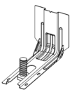
Install Anti-Tip Bracket
1. Remove the anti-tip bracket from the inside of the oven.
2. Determine which mounting method to use: floor or wall. If you have a stone or masonry floor, you can use the wall mounting method. If you are installing the range in a mobile home, you must secure the range to the floor. This anti-tip bracket and screws can be used with wood or metal studs.
3. Determine and mark centerline of the cutout space. The mounting bracket can be installed on either the left-hand or right-hand side of the cutout. Position mounting bracket against the wall in the cutout so that the V-notch of the bracket is 121/2" (31.8 cm) from centerline, as shown.
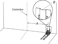
A. 121/2" (31.8 cm) B. Bracket V-notch
4. Drill two 1/8" (3 mm) holes that correspond to the bracket holes of the determined mounting method. See the following illustrations.
Floor Mounting
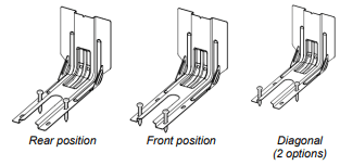
Wall Mounting
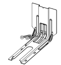
5. Using the two #10 x 15/8" (41 mm) Phillips-head screws provided, mount anti-tip bracket to the wall or floor.
6. Move range close enough to opening to allow for final electrical connections. Remove shipping base, cardboard or hardboard from under range.
7. Move range into its final location, making sure rear leveling leg slides into anti-tip bracket.
8. Move range forward onto shipping base, cardboard, or hardboard to continue installing the range, using the following installation instructions.
Adjust Leveling Legs
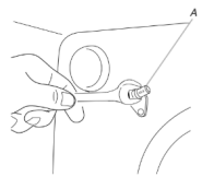
1. If range height adjustment is necessary, use a wrench or pliers to loosen the four leveling legs. This may be done with the range on its back or with the range supported on two legs after the range has been placed back to a standing position. NOTE: To place range back up into a standing position, put a sheet of cardboard or hardboard in front of range. Using two or more people, stand range back up onto the cardboard or hardboard.
2. Measure the distance from the top of the counter to the floor.
3. Measure the distance from the top of the cooktop to the bottom of the leveling legs. This distance should be the same. If it is not, adjust the leveling legs to the correct height. The leveling legs can be loosened to add up to a maximum of 1" (2.5 cm). A minimum of 3/16" (5 mm) is needed to engage the anti-tip bracket. NOTE: If height adjustment is made when range is standing, tilt the range back to adjust the front legs, and then tilt forward to adjust the rear legs.
4. When the range is at the correct height, check that there is adequate clearance under the range for the anti-tip bracket. Before sliding range into its final location, check that the antitip bracket will slide under the range and onto the rear leveling leg prior to anti-tip bracket installation. NOTE: If a Trim Kit will be used, the top of the cooktop should be higher than the counter. See the Installation Instructions included with the Trim Kit for the correct height.
Level Range
1. Place level on the oven bottom, as indicated in one of the two figures below, depending on the size of the level. Check with the level side to side and front to back.
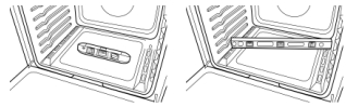
2. If range is not level, use a wrench or pliers to adjust leveling legs up or down until the range is level. NOTE: Range must be level for satisfactory baking performance and best cleaning results using AquaLift® SelfClean Technology
Make Gas Connection
This range is factory-set for use with Natural gas. To use this range with propane gas, see the “Gas Conversions” section before connecting this range to the gas supply. Gas conversions from Natural gas to Propane gas or from Propane gas to Natural gas must be done by a qualified installer.
Typical flexible connection
1. Apply pipe-joint compound made for use with Propane gas to the smaller thread ends of the flexible connector adapters (see B and G in the following illustration).
2. Attach one adapter to the gas pressure regulator and the other adapter to the gas shutoff valve. Tighten both adapters, being certain not to move or turn the gas pressure regulator. 3. Use a 15/16" (2.4 cm) combination wrench and an adjustable wrench to attach the flexible connector to the adapters.
IMPORTANT: All connections must be wrench-tightened. Do not make connections to the gas regulator too tight. Making the connections too tight may crack the regulator and cause a gas leak. Do not allow the regulator to turn when tightening fittings.
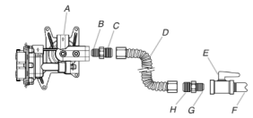
A. Gas pressure regulator
B. Use pipe-joint compound.
C. Adapter (must have 1/2" [1.3 cm] male pipe thread)
D. Flexible connector
E. Manual gas shutoff valve
F. 1/2" (1.3 cm) or 3/4" (1.9 cm) gas pipe
G. Use pipe-joint compound.
H. Adapter
Complete Connection
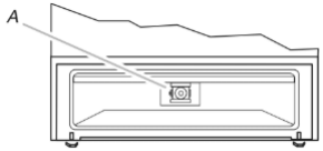
1. Check that the gas pressure regulator shut-off valve is in the “on” position.
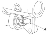
A. Gas pressure regulator shut-off valve shown in the “on” position
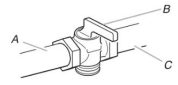
2. Open the manual shut-off valve in the gas supply line. The valve is open when the handle is parallel to the gas pipe.
A. Closed valve B. Open valve
3. Test all connections by brushing on an approved noncorrosive leak-detection solution. If bubbles appear, a leak is indicated. Correct any leak found.
4. Remove cooktop burner caps and bases from package containing parts. Place the burner bases as indicated by the following illustration for your model:
For models WEG745H0F and MGS8800F:
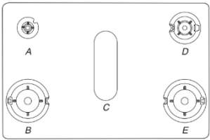
A. Small (Auxiliary)
B. Large (Ultra Rapid)
C. Oval (OV)
D. Medium (Semi Rapid)
E. Large (Ultra Rapid)
For model KSGG700E:
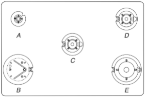
A. Small (Auxiliary)
B. X-Large (Stack)
C. Medium (Semi Rapid)
D. Medium (Semi Rapid)
E. Large (Ultra Rapid)
For model KSGB900E:
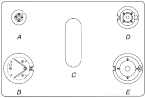
A. Small (Auxiliary)
B. X-Large (Stack)
C. Oval (OV)
D. Medium (Semi Rapid)
E. Large (Ultra Rapid)
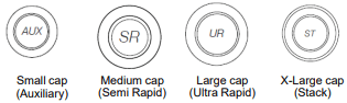
NOTE: Each round burner base is marked with one of the following: AUX, SR, UR, ST.
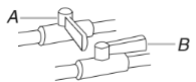
5. Align the gas tube opening in the burner base with the orifice holder on the cooktop and the igniter electrode with the notch in the burner base.
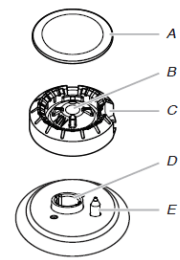
A. Burner cap
B. Gas tube opening
C. Burner base
D. Orifice holder
E. Igniter electrode
6. Place the burner caps on the appropriate burner bases.
IMPORTANT: The bottom of the small and medium caps are different. Do not put the wrong size burner cap on the burner base. Each round burner cap is marked with an AUX, SR, UR, or ST to match with a letter on the burner base.
Burner caps should be level when properly positioned. If burner caps are not properly positioned, surface burners will not light. The burner cap should not rock or wobble when properly aligned.

A. Incorrect B. Correct
7. Plug into a grounded 3-prong outlet.
Verify Anti-Tip Bracket Is Installed and Engaged
On Ranges Equipped with a Premium Storage Drawer:
1. Slide range into final location, making sure rear leveling leg slides into anti-tip bracket.
2. Remove the premium storage drawer. See the “Remove/ Replace Drawer” section.
3. Use a flashlight to look underneath the bottom of the range.
4. Visually check that the rear range foot is inserted into the slot of the anti-tip bracket.
On Ranges Equipped with a Warming Drawer or Baking Drawer:
1. Slide range into final location, making sure rear leveling leg slides into anti-tip bracket. Leave a 1" (2.5 cm) gap between the back of the range and the back wall.
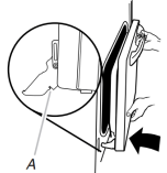
2. Place the outside of your foot against the bottom front of the warming drawer or baking drawer to keep the range from moving, and then grasp the back of the range, as shown.
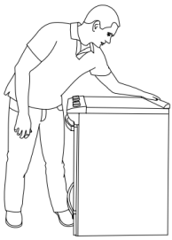
3. Slowly attempt to tilt the range forward. If you encounter immediate resistance, the range foot is engaged in the anti-tip bracket. Go to Step 8.
4. If the rear of the range lifts more than 1/2" (1.3 cm) off the floor without resistance, stop tilting the range and lower it gently back to the floor. The range foot is not engaged in the anti-tip bracket. IMPORTANT: If there is a snapping or popping sound when lifting the range, the range may not be fully engaged in the bracket. Check to see if there are obstructions keeping the range from sliding to the wall or keeping the range foot from sliding into the bracket. Verify that the bracket is held securely in place by the mounting screws.
5. Slide the range forward, and verify that the anti-tip bracket is securely attached to the floor or wall.
6. Slide range back so the rear range foot is inserted into the slot of the anti-tip bracket.
7. Repeat steps 1 and 2 to ensure that the range foot is engaged in the anti-tip bracket. If the rear of the range lifts more than 1/2" (1.3 cm) off the floor without resistance, the anti-tip bracket may not be installed correctly. Do not operate the range without anti-tip bracket installed and engaged. Please reference the Quick Start Guide for contact information.
8. Move the range into its final location. Check that the range is level by placing a level on the oven bottom. See the “Level Range” section. IMPORTANT: If the range is moved to adjust the leveling legs, verify that the anti-tip bracket is engaged by repeating steps 1 to 8.
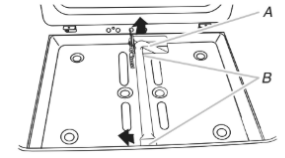
Remove/Replace Drawer (On some models)
Remove all items from inside the baking drawer, warming drawer or premium storage drawer, and then allow the range to cool completely before attempting to remove the drawer.
To Remove:
1. Open the drawer to its fully open position.
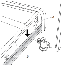
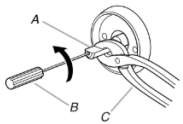
2. Using a flat-blade screwdriver, gently loosen the drawer from the glide alignment notch, and then lift up the drawer alignment tab from the glide.
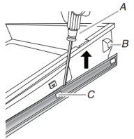
A. Flat-blade screwdriver
B. Drawer alignment tab
C. Drawer glide notch
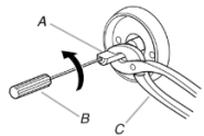
3. Repeat Step 2 on the other side. The drawer is no longer attached to the drawer glides. Using both hands, pick up the drawer to complete the removal.
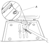
To Replace:
1. Align the forward drawer notches with the notches in the drawer glides on both sides. Place the rear alignment tabs into the drawer glides on both sides.
A. Drawer alignment tab
B. Drawer glide notch
2. Push the warming drawer or premium storage drawer in all the way.
3. Gently open and close the warming drawer or premium storage drawer to ensure it is seated properly on the glides on both sides.
Oven Door
For normal range use, it is not suggested to remove the oven door. However, if removal is necessary, make sure the oven is OFF and cool. Then, follow these instructions. The oven door is heavy.
To Remove:
1. Open oven door all the way.
2. Pinch the hinge latch between two fingers and pull forward. Repeat on other side of oven door.
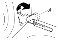
A. Hinge Latch
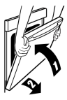
3. Close the oven door as far as it will shut.
4. Lift the oven door while holding both sides. Continue to push the oven door closed and pull it away from the oven door frame.
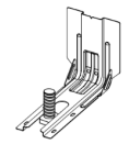
To Replace:
1. Insert both hanger arms into the door. Be sure that the hinge notches are engaged in the oven door frame.
A. Hinge notch
2. Open the oven door. The door should be able to open all the way.
3. Move the hinge levers back to the “locked” position. Check that the door is free to open and close and is level while closed. If it is not, repeat the removal and installation procedures.
Complete Installation
- Check that all parts are now installed. If there is an extra part, go back through the steps to see which step was skipped.
- Check that you have all of your tools.
- Check that you have all of the range accessories, especially oven racks. These accessories may be in the range packaging.
- Dispose of/recycle all packaging materials.
- Check that the range is level. See the “Level Range” section.
- Use a mild solution of liquid household cleaner and warm water to remove waxy residue caused by shipping material. Dry thoroughly with a soft cloth. For more information, see the “Range Maintenance and Care” section.
- Read the Quick Start Guide.
- Turn on surface burners and oven. See the Quick Start Guide for specific instructions on range operation.
NOTE: Odors and smoke are normal when the oven is used the first few times.
GAS CONVERSIONS
Propane Gas Conversion
1. Turn manual shutoff valve to the closed position.
A. Gas supply line
B. Manual shut-off valve closed position
C. To range
2. Unplug range or disconnect power.
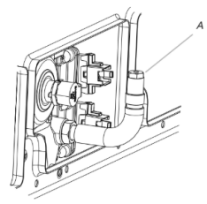
To Convert Gas Pressure Regulator (Natural gas to Propane)
1. Remove the premium storage drawer, warming drawer or baking drawer. See the “Remove/Replace Drawer”, “Storage Drawer” or “Warming Drawer or Premium Storage Drawer” section.
2. Locate gas pressure regulator at rear of the drawer compartment.
NOTE: On models with a warming drawer or baking drawer, an access cover must be removed to access the gas pressure regulator.
A. Gas pressure regulator
IMPORTANT: Do not remove the gas pressure regulator.
3. Remove plastic cover from gas pressure regulator cap.
4. Turn gas pressure regulator cap counterclockwise with a 5/8" (1.6 cm) combination wrench to remove. NOTE: Do not remove the spring beneath the cap.
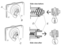
A. Plastic cover
B. Gas pressure regulator cap with solid end facing out
C. Gas pressure regulator cap with hollow end facing out
D. Washer
E. Gas pressure regulator cap
5. Turn over the gas pressure regulator cap and reinstall on regulator so that the hollow end faces out and the marking “↓LP” is facing the direction shown in the above drawing.
6. Replace plastic cover over gas pressure regulator cap.
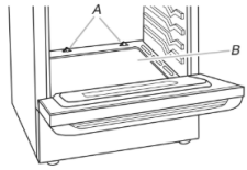
To Convert Oven Bake Burner (Natural Gas to Propane Gas)
1. Remove the oven racks and the oven door. See the “Oven Door” section.
2. Remove two screws and washers at the rear of the oven bottom.
3. Lift the rear of the oven bottom up and back until the front of the panel is away from the front frame. Remove from oven and set it aside on a covered surface.
A. Screws B. Oven bottom
4. Remove two screws from the bake burner.
5. Slide the front of the bake burner to the side to remove tab from front of oven. Lift the back of the bake burner off the oven orifice and set the bake burner aside. Do not disconnect the wire.
A. Bake burner B. Screws
A. Oven orifice
6. Apply masking tape to the end of a 3/8" (9.5 mm) nut driver to help hold the gas orifice spud in the nut driver while changing it. Press nut driver down onto the gas orifice spud and remove by turning the Natural gas bake burner orifice spud counterclockwise to remove. The spud will be stamped with a “47.”
7. Replace the “47” spud with a “56” spud. Install the Propane gas bake burner orifice spud, turning it clockwise until snug. IMPORTANT: Do not overtighten.
A. Orifice spud
8. Position the back of the bake burner over the oven orifice, and then align the holes for the screws.
9. Reattach the bake burner with two screws.
10. Position the front of the oven bottom panel toward the front frame, and then lower the rear of the oven bottom panel into the oven.
11. Reattach the oven bottom panel with two screws and two washers.
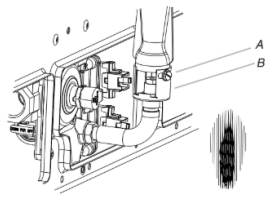
To Convert Oven Broil Burner (Natural Gas to Propane Gas)
1. Remove the one screw from the broil burner.
2. Remove the flame spreader.
3. Remove the broil burner from the broil burner orifice hood. NOTE: The broil burner will hang in the back of the oven while changing the orifice hood.
A. Broil burner
B. Flame spreader
C. Screws
D. Orifice hood
4. Apply masking tape to the end of a 3/8" (1 cm) nut driver to help hold the gas orifice spud in the nut driver while changing it. Press nut driver down onto the gas orifice spud and remove by turning the Natural gas broil burner orifice hood counterclockwise to remove. The hood will be stamped with a “155”.
5. Replace the “155” hood with a “100” hood. Install the Propane gas broiler burner orifice hood, turning it clockwise until snug. IMPORTANT: Do not overtighten.
A. Orifice hood
6. Place the broil burner on the broil burner orifice hood. Insert the broil burner ceramic igniter in the hole in the rear of the oven.
7. Replace the flame spreader with all four tabs facing up and the notches toward the rear of the oven.
8. Position the broil burner against the top of the oven and attach it with one screw.
9. Replace premium storage drawer/storage drawer, warming drawer or baking drawer. See the “Remove/Replace Drawer” section.
10. Replace the oven door. See the “Oven Door” section.
11. Replace the oven racks.
Complete Installation (Natural Gas to Propane Gas)
1. Refer to the “Make Gas Connection” section for properly connecting the range to the gas supply.
2. Refer to the “Electronic Ignition System” section for proper burner ignition, operation.
3. Refer to the “Adjust Flame Height” section for burner flame adjustments.
IMPORTANT: You may have to adjust the low setting for each cooktop burner. Checking for proper cooktop flame is very important. The small inner cone should have a very distinct blue flame 1/4" to 1/2" (6.4 to 13 mm) long. The outer cone is not as distinct as the inner cone. Propane gas flames have a slightly yellow tip.
4. Refer to “Complete Installation” in the “Installation Instructions” section of these instructions to complete this procedure.
IMPORTANT: Make sure to save the orifices that have just been replaced in the conversion.
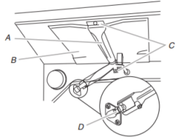
Adjust Flame Height
To Adjust Standard Burner:
The flame can be adjusted using the adjustment screw in the center of the valve stem. The valve stem is located directly underneath the control knob.
If the “Low” Flame Needs to Be Adjusted:
1. Light 1 burner and turn to lowest setting.
2. Remove the control knob. Hold the knob stem with a pair of pliers. Use a small flatblade screwdriver to turn the screw located in the center of the control knob stem until the flame is the proper size. Turning the screw clockwise will increase the flame size and counterclockwise will decrease the flame size.
A. Control knob stem
B. Screwdriver
C. Pliers
3. Replace the control knob.
4. Test the flame by turning the control from the low position to the high position, checking the flame at each setting.
5. Repeat the previous steps for each burner.
To Adjust Double Burner (On Some Models):
1. Light burner and turn to lowest setting where both inner and outer burners are lit.
2. Remove the control knob.
3. Insert a 1/8" (3 mm) flat-blade screwdriver into the adjustment locations shown in the following illustration and engage the slotted screw. Turn the screw until the flame is the proper size. Turning the screw clockwise will increase the flame size and counterclockwise will decrease the flame size.
A. Control knob stem
B. Screwdriver
C. Pliers
4. Replace the control knob.
5. Test the flame by turning the control from the low position to the high position, checking the flame at each setting.
Check Operation of Oven Bake Burner
Refer to the Quick Start Guide and online Control Guide for proper operation of the oven controls
Adjust Oven Bake Burner Flame (If Needed)
1. Remove the premium storage drawer, warming drawer or baking drawer or storage drawer(see the “Remove/Replace Drawer” section).
2. Locate gas pressure regulator at rear of the drawer compartment.
A. Gas pressure regulator
IMPORTANT: Do not remove the gas pressure regulator.
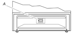
3. Check the oven bake burner for proper flame.
a. Remove the oven racks.
b. To remove the oven bottom: Remove 2 screws at the rear of the oven bottom. Lift the rear of the oven bottom up and back until the front of the panel is away from the front frame. Remove from oven and place on a covered surface.
A. Screws B. Oven bottom
c. Press BAKE.
d. Press the Start pad.
The oven bake burner should light within 8 seconds. Under certain conditions, it may take the burner up to 50 to 60 seconds to light.
Electronic igniters are used to light the bake and broil burners.
This flame should have a 1/2" (1.3 cm) long inner cone of bluish-green with an outer mantle of dark blue and should be clean and soft in character. No yellow tips, blowing, or lifting of flame should occur.
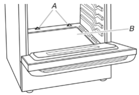
4. If the oven bake flame needs to be adjusted, locate the air shutter near the center rear of the drawer cavity behind the access panel. Loosen the locking screw and rotate the air shutter until the proper flame appears. Tighten locking screw.
A. Locking screw B. Air shutter
5. Push the Off pad when finished.
6. Reinstall the oven bottom and the storage drawer (see the “Remove/Replace Drawer” section).
Adjust Oven Broil Burner Flame (If Needed)
Press BROIL, and then press the start pad. Look through the oven window to check broil burner for proper flame. This flame should have a 1/2" (1.3 cm) long inner cone of bluish-green with an outer mantle of dark blue and should be clean and soft in character. No yellow tips, blowing, or lifting of flame should be present.
If Flame Needs to be Adjusted:
1. Press the Off pad. Let the oven cool.
2. Loosen the lock screw on the air shutter located at the rear of the broil burner.
3. Adjust the air shutter as needed.
4. Tighten lock screw.
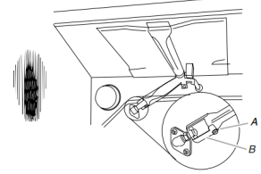
A. Lock screw B. Air shutter
5. Close the oven door. Press BROIL, and then press the Start pad. Look through the oven window to check broil burner for proper flame. If flame needs to be adjusted, repeat steps 1 to 5.
Moving the Range
When moving range, slide range onto cardboard or hardboard to avoid damaging the floor covering.
If removing the range is necessary for cleaning or maintenance:
For power supply cord-connected ranges:
- Slide range forward.
- Turn manual shutoff valve to the closed position.
- Unplug the power supply cord.
- Disconnect the gas supply tubing.
- Complete cleaning or maintenance.
- Reconnect the gas supply tubing.
- Open the manual shutoff valve in the gas supply line.
- Plug in power supply cord.
- Slide range back so rear range foot is under anti-tip bracket.
10. Refer to the “Verify Anti-Tip Bracket Is Installed and Engaged” section to verify engagement.
11. Check that range is level.