Loading ...
Loading ...
Loading ...
MK / MKT (E5) 08/2020 page 108/162
19. Zero-voltage switching outputs via operation lines
The chambers are equipped regularly (MKT) or optionally (MK) with four zero-voltage switching outputs
(DIN sockets (7) and (8) located in the lateral control panel).
The operation lines serve to switch any device connected to the zero-voltage relay output. They can be
programmed On/Off in Fixed value and program modes.
Connection for operation lines “Switching output 1” and “2” occurs via DIN socket (7), connection for oper-
ation lines “Switching output 3” and “4” via DIN socket (8) in the lateral control panel:
OUTPUT TRACK 1+2
24V/MAX.2,5A
OUTPUT TRACK 3+4
24V/MAX.2,5A
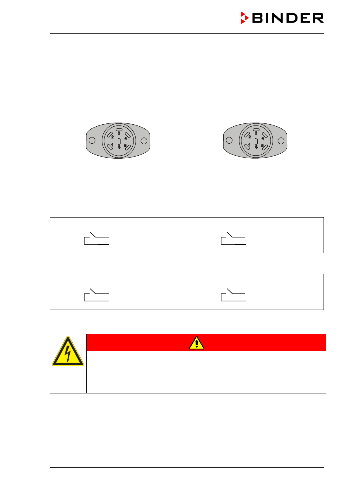
Figure 16: Pin configuration of DIN sockets (7) left and (8) right
DIN socket (7):
Operation line “Switching output 1” Operation line “Switching output 2”
Pin 1: Pin
Pin 2: Make
Pin 4: Pin
Pin 5: Make
DIN socket (8):
Operation line “Switching output 3” Operation line “Switching output 4”
Pin 1: Pin
Pin 2: Make
Pin 4: Pin
Pin 5: Make
Maximum loading capacity of the switching contacts: 24V AC/DC – 2.5 A
DANGER
Electrical hazard through overload of contacts.
Deadly electric shock. Damage to the switching contacts and connection socket.
∅ Do NOT exceed the maximum switching load of 24V AC/DC – 2.5A.
∅ Do NOT connect any devices with a higher loading capacity.
1
2
4
5
1
2
4
5
Loading ...
Loading ...
Loading ...