Loading ...
Loading ...
Loading ...
2
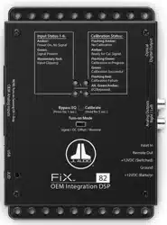
OEM Input Connections
The FiX™ 82 accepts up to eight channels (four stereo pairs) of full-range or
band-limited output from an OEM audio source (250 mV – 30 V RMS). Engineered
to combat induced cable noise, the input architecture is set up in a differential-
balanced configuration, making these inputs compatible with virtually any
analog audio signal. Connections are made via four plugs located on the side of
the unit labeled “OEM Analog Inputs”. Each 4-pin plug accepts two channels of
audio input, separated in pairs (Left and Right).
Depending on the specific architecture of your OEM system, you will need to
locate suitable connection points to provide appropriate input signals to the
FiX™ 82, while maintaining OEM functionality. It is recommended to obtain a
service manual for the vehicle you are working on to locate and identify the
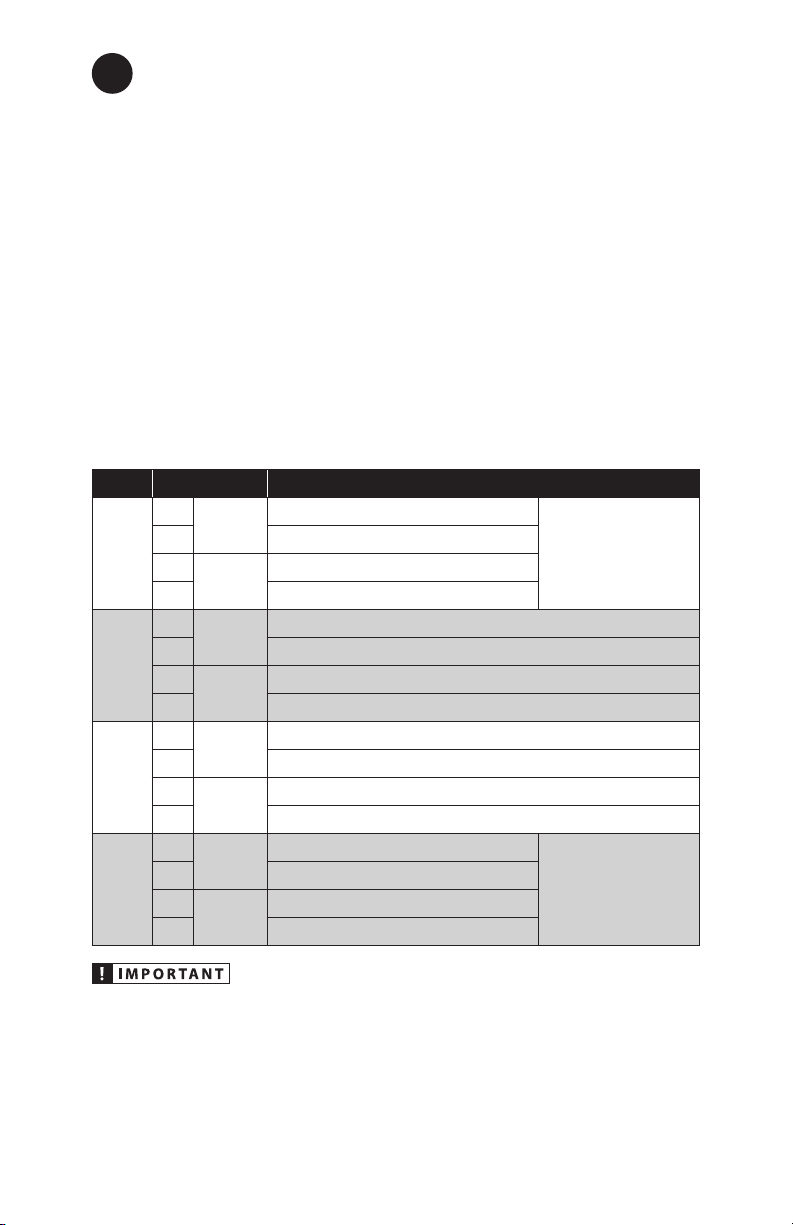
correct OEM wires. Refer to the table below when making connections with your
OEM audio source. Note: With most factory audio systems, it is not necessary
to connect all eight input channels of the FiX™ 82. We recommend using the
least amount of inputs needed to create a full-range audio signal.
Plug Connection Description
1/2
L+
Ch. 1
input
(+) Positive Left Channel Signal
Ch. 1 is the monitored
channel for the auto
turn-on circuitry. (Make
sure Ch. 1 & 2 inputs
contain midrange
signals.)
L– (–) Negative Left Channel Signal
R+
Ch. 2
input
(+) Positive Right Channel Signal
R– (–) Negative Right Channel Signal
3/4
L+
Ch. 3
input
(+) Positive Left Channel Signal
L– (–) Negative Left Channel Signal
R+
Ch. 4
input
(+) Positive Right Channel Signal
R– (–) Negative Right Channel Signal
5/6
L+
Ch. 5
input
(+) Positive Left Channel Signal
L– (–) Negative Left Channel Signal
R+
Ch. 6
input
(+) Positive Right Channel Signal
R– (–) Negative Right Channel Signal
7/8
(SUB)
L+
Ch. 7
input
(+) Positive Left Channel Signal
If the OEM subwoofer
signal is mono (one
ch. only), connect it to
both the left and right
channels, in parallel.
L– (–) Negative Left Channel Signal
R+
Ch. 8
input
(+) Positive Right Channel Signal
R– (–) Negative Right Channel Signal
It is very easy to damage expensive vehicle systems in modern automobiles.
Never assume that you have found appropriate wires without consulting
a reliable wiring diagram or without performing signal testing with safe
test equipment. If you are uncomfortable with reading diagrams or testing
signals, please enlist the services of your authorized JL Audio dealer to
perform the installation.
Loading ...
Loading ...
Loading ...