Loading ...
Loading ...
Loading ...

2
OEM Input Connections continued...
It is vital to observe the correct electrical polarity of each channel’s input
signal. Failure to do so can result in improper calibration, loss of signal and
poor performance.
Some factory audio amplifiers employ a load detection circuit that looks for
a low-impedance load (expecting a speaker) in order to enable audio output.
When a high-impedance load like the input section of the FiX™ 82 is connected
to these factory amplifiers, the audio outputs will mute.
After installing the FiX™ 82 and turning on the audio system, if there is no
output from the factory amplifier, a FiX-LSA-4 Load-Sensing Adaptor (sold
separately) will need to be inserted inline with the FiX™ 82’s inputs. The FiX-
LSA-4 presents a safe and appropriate load to the factory amplifier and corrects
the muting behavior. Refer to the FiX-LSA-4 manual for detailed instructions.
3
Output Connections
The FiX™ 82 offers two output types to feed audio signals to your aftermarket
system. Choose the output type that is appropriate for the specific equipment
of your audio system.
Analog Outputs: Two RCA-type, 4-volt (RMS) line-level output jacks are
located next to the “Power Connector” and are labeled for each channel (Left
and Right). Analog outputs are compatible with most types of aftermarket
signal processors or amplifiers. The level of this output is proportionate to the
FiX™ 82’s input signal and may also be controlled by the optional DRC-100
Digital Remote Controller (sold separately).
Optical Digital Output: Located next to the “Analog Outputs”, this jack
provides a digital audio output that is not susceptible to RF interference or
noise-generating electrical conditions. This digital output is intended for use
with a TwK™ System Tuning DSP (sold separately) or other signal processors or
amplifiers that have an optical (Toslink) digital audio input (S/PDIF) jack. The
level of this output is proportionate to the FiX™ 82’s input signal and is not
affected when used with the optional DRC-100 Digital Remote Controller (sold
separately). For remote level control, you may use the DRC-200 Digital Remote
Controller that is included with the TwK™ System Tuning DSP (sold separately).
4
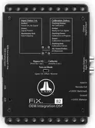
Status LEDs
Located on top of the unit are two sets of LEDs used to report the status of the
FiX™ 82. Arranged in left (L) and right (R) pairs, the LEDs are divided by category
(Input Status and Calibration Status) and may be referenced during setup,
calibration and normal use. Refer to the markings above the LEDs for specific
behavior definitions.
Loading ...
Loading ...
Loading ...