Loading ...
Loading ...
Loading ...

1
Power Connections
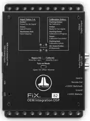
The FiX™ 82 has a 5-pin “Power Connector” jack located next to the “Analog
Outputs”. The Power Connector jack accepts the removable 5-pin plug and is
used to make the connections below.
Plug Connection Description
Power Connector
+12VDC (Battery) Positive (+12V) Power Connection
Ground Negative (GND) Ground Connection
+12VDC (Switched) Positive (+12V) Turn-On Input
Remote Out Positive (+12V) Turn-On Output
Valet In Negative (GND) Ground Input (used to activate Valet Mode)
Never make power connections with a “live” wire. Always disconnect
the vehicle’s negative battery post before making any connections or
adjustments to 12V power connections! Failure to make safe, tight,
high-integrity connections can result in fire and extensive damage.
1. Disconnect the vehicle’s NEGATIVE battery post connection and secure the
disconnected cable to prevent accidental reconnection during installation.
This is an essential safety precaution during installation!
2. +12VDC (Battery): Connect to a constant positive (+12V) source. The
internal circuitry of this connection is equipped with a self-resetting fuse
designed to protect the unit internally. To protect the vehicle and its
electrical system from damage, always install an appropriate fuse within
18 inches (45 cm) of the +12V connection point. If this is the only device
using the connection point, we recommend using a 1A fuse.
3. Ground: Connect to a clean, solid metal grounding point. Ideally, the
+12VDC (Battery) and Ground connections should be run to the same
distribution points that the amplifiers use for their power and ground
connections. This will minimize the possibility of noise in the system.
4. +12VDC (Switched): This connection, along with the “Turn-on Mode”
switch setting, determines the turn-on operation of the FiX™ 82. Connect
this to the positive (+12V) remote turn-on output of your source unit, if
equipped. If your source unit is not equipped with a dedicated remote
turn-on output, refer to the “Turn-on Mode” section for more options.
5. Remote Out: This connection provides a positive (+12V) turn-on voltage
(100 mA limit) to activate other aftermarket signal processors or amplifiers
(similar to an aftermarket head unit’s remote turn-on lead). If your
equipment requires more than 100 mA total for activation, this connection
can be used to trigger a relay to control the equipment in your system.
6. Valet In: Connect this to negative Ground to activate Valet Mode.
When Valet Mode is active, the FiX™ 82’s outputs are attenuated by
15 dB and its JLID status LED will flash slow green. Valet Mode can
be used to prevent damage to the audio system from unwanted or
unauthorized use when your vehicle is being serviced, valet parked,
etc. Due to the covert nature of this function, we recommend
concealing the location and/or method of its activation. This can be
accomplished with a hidden toggle switch (not supplied) or other
disguised mechanism to apply negative ground to this connection.
Loading ...
Loading ...
Loading ...