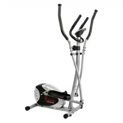
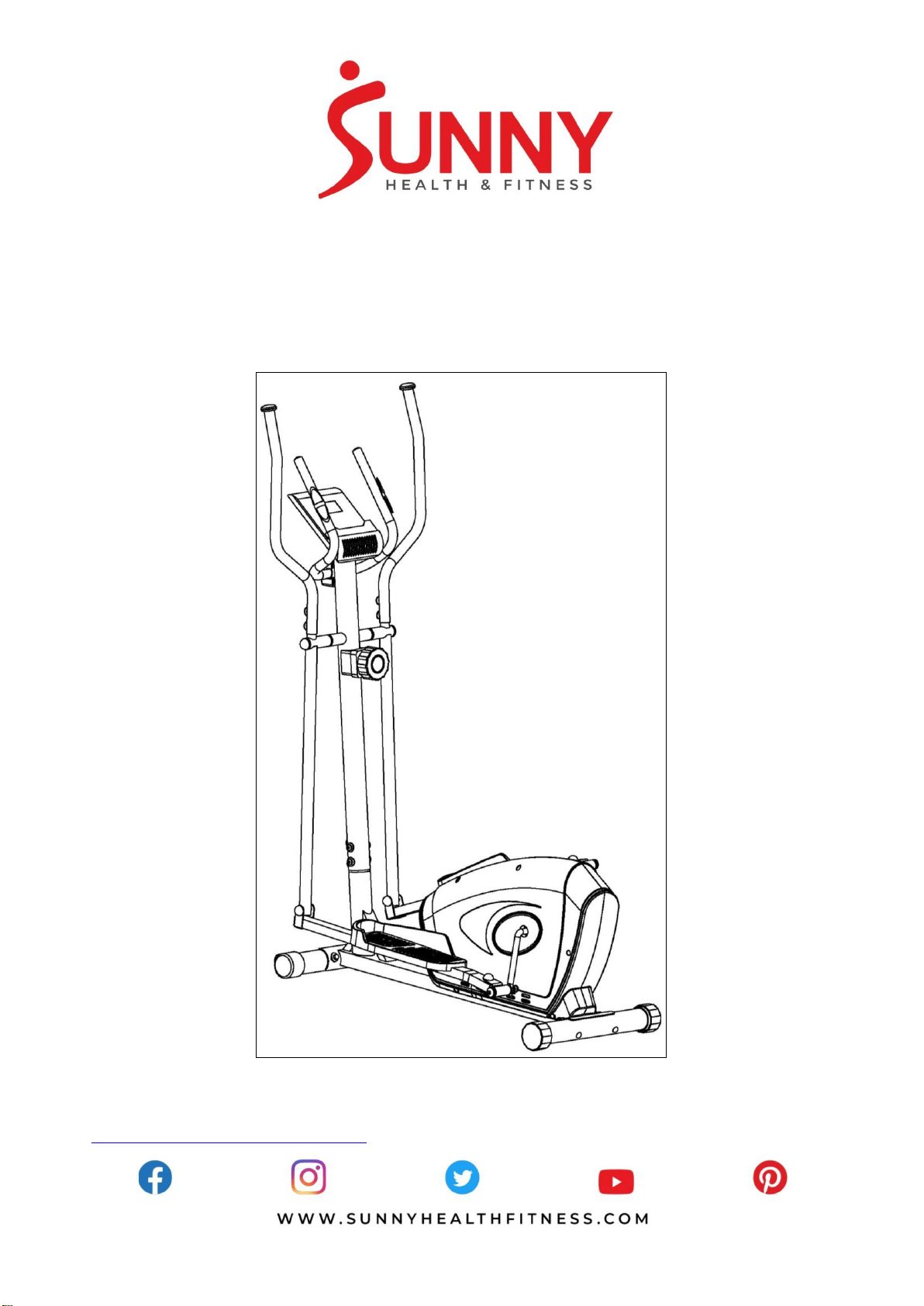
MAGNETIC ELLIPTICAL TRAINER
SF-E3607
USER MANUAL
IMPORTANT! Please retain owner’s manual for maintenance and adjustment instructions. Your
satisfaction is very important to us, PLEASE DO NOT RETURN UNTIL YOU HAVE CONTACTED
US: [email protected] or 1- 877 - 90SUNNY (877-907-8669).


1
IMPORTANT SAFETY INFORMATION
We thank you for choosing our product. To ensure your safety and health, please use this
equipment correctly. It is important to read this entire manual before assembling and using the
equipment. Safe and effective use can only be achieved if the equipment is assembled,
maintained and used properly. It is your responsibility to ensure that all users of the equipment are
informed of all warnings and precautions.
1. Before starting any exercise program, you should consult your physician to determine if you
have any medical or physical conditions that could put your health and safety at risk, or prevent
you from using the equipment properly. Your physician’s advice is essential if you are taking
medication that affects your heart rate, blood pressure or cholesterol level.
2. Be aware of your body’s signals. Incorrect or excessive exercise can damage your health. Stop
exercising if you experience any of the following symptoms: pain, tightness in your chest,
irregular heartbeat, shortness of breath, lightheadedness, dizziness or feelings of nausea. If
you do experience any of these conditions, you should consult your physician before
continuing with your exercise program.
3. Keep children and pets away from the equipment. The equipment is designed for adult use
only.
4. Use the equipment on a solid, flat level surface with a protective cover for your floor or carpet.
To ensure safety, the equipment should have at least 2 feet (60 CM) of free space all around it.
5. Ensure that all nuts and bolts are securely tightened before using the equipment. The safety of
the equipment can only be maintained if it is regularly examined for damage and/or wear and
tear.
6. Always use the equipment as indicated. If you find any defective components while assembling
or checking the equipment, or if you hear any unusual noises coming from the equipment
during exercise, discontinue use of the equipment immediately and do not use until the
problem has been rectified.
7. Wear suitable clothing while using the equipment. Avoid wearing loose clothing that may
become entangled in the equipment.
8. Do not place fingers or objects into the moving parts of the equipment.
9. The maximum weight capacity of this unit is 220 pounds (100 KG).
10. The equipment is not suitable for therapeutic use.
11. To avoid bodily injury and/or damage to the product or property, proper lifting and moving is
required.
12. Your product is intended for use in cool, dry conditions. You should avoid storage in extreme
cold, hot or damp areas as this may lead to corrosion and other related problems.
13. This equipment is designed for indoor and home use only, it is not intended for commercial use!
2
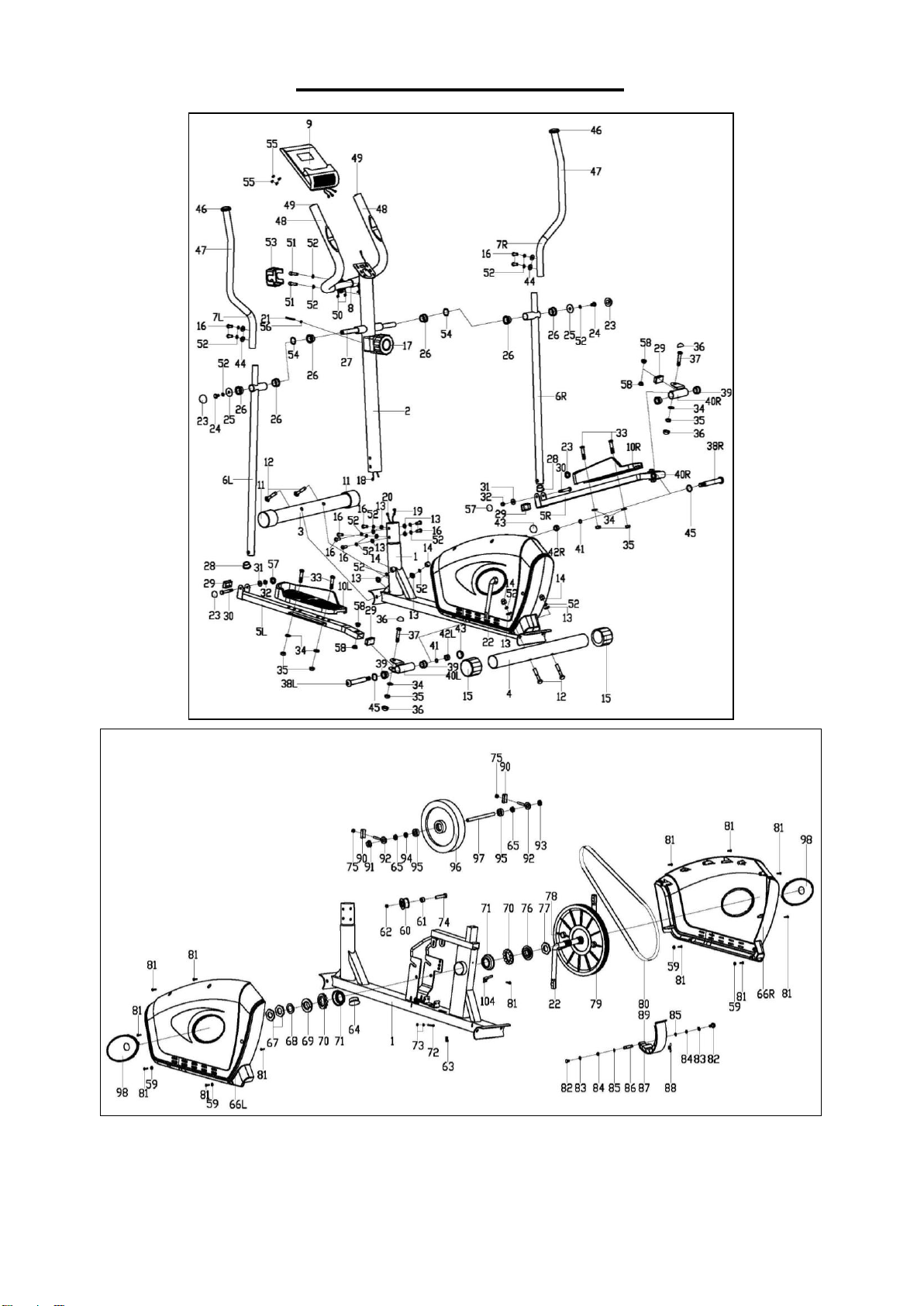
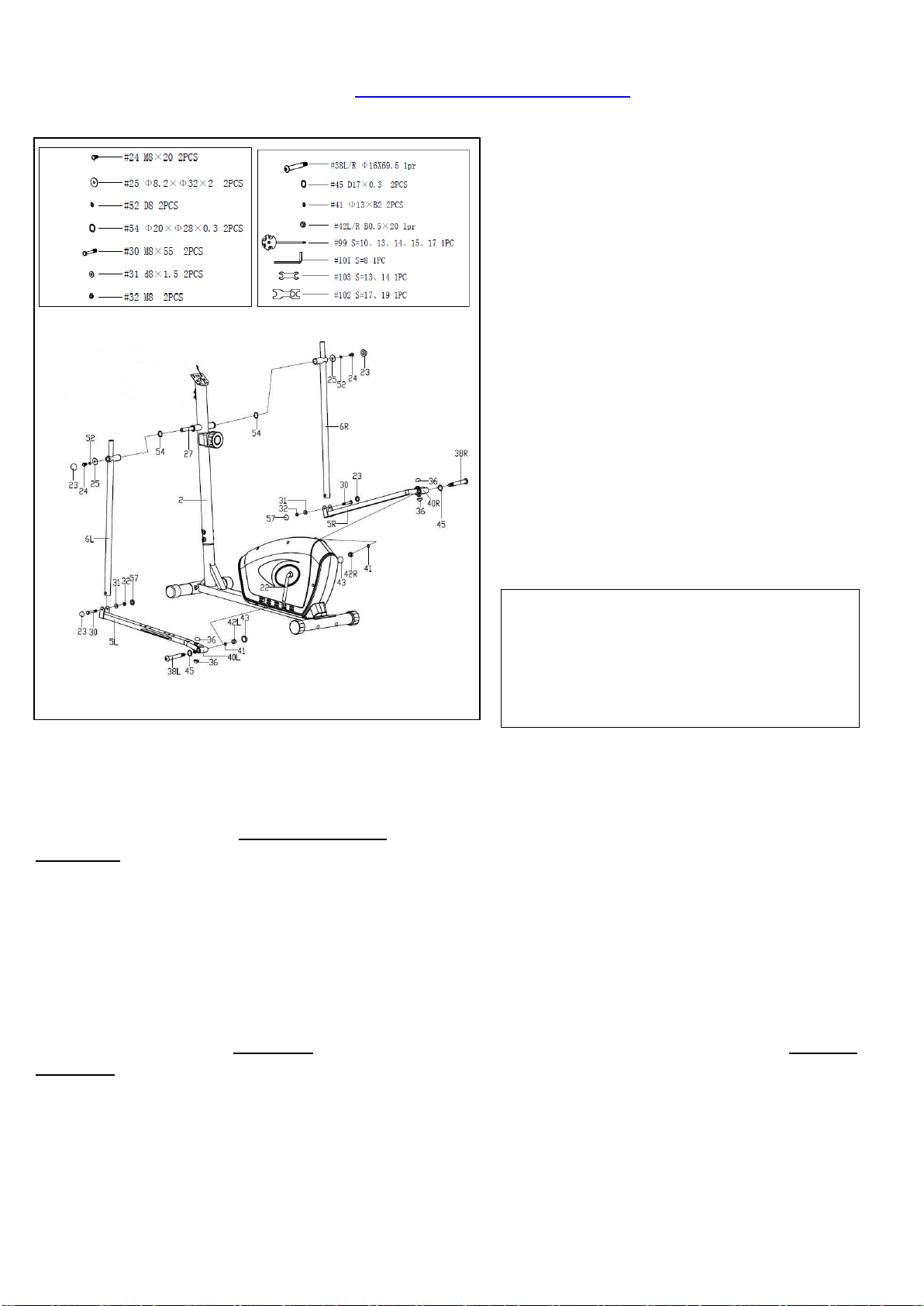
EXPLODED DIAGRAM

3
PARTS LIST
No.
Description
Spec.
Qty.
No.
Description
Spec.
Qty.
1
Main Frame
1
49
Round Cap
Φ25x1.5
2
2
Handlebar Post
1
50
Pulse Wire
2
3
Front Stabilizer
1
51
Inner Hex Bolt
M8x30
2
4
Rear Stabilizer
1
52
Spring Washer
D8
18
5L/R
Pedal Support
1 pr.
53
Clamp Cover
1
6L/R
Swing Tube
1 pr.
54
Wave Washer
Φ20xΦ28x0.3
2
7L/R
Handlebar
1 pr.
55
Cross Pan Head Screw
M4x12
4
8
Handlebar
1
56
Arc Washer
1
9
Computer
1
57
Cap
S13
2
10L/R
Pedal
1 pr.
58
Bushing
Φ14x10xΦ10.1
4
11
Front End Cap
2
59
Flat Washer
D5x1
4
12
Carriage Bolt
M8x76
4
60
Idler
1
13
Arc Washer
Φ20xΦ8.5xR30
10
61
Spacer
1
14
Acorn Nut
M8
4
62
Nylon Nut
M10
1
15
Rear End Cap
2
63
Spring
1
16
Inner Hex Bolt
M8x16
10
64
Round Cap
1
17
Tension Controller
1
65
Conical Thin Nut
M10×1
2
18
Extension Wire
1
66L/R
Belt Cover
1 pr.
19
Tension Cable
1
67
Nut
2
20
Sensor Wire
1
68
Washer
1
21
Cross Pan Head
Screw
M5x55
1
69
Two Slot Nut
1
22
Crank
1
70
Ball Bearing
2
23
Cap
S14
4
71
Central Bowl
2
24
Hex Bolt
M8x20
2
72
Hex Bolt
1
25
Flat Washer
Φ8.2xΦ32x2
2
73
Hex Screw
M5
2
26
Bushing
Φ32x2.5
6
74
Hex Bolt
M10x40
1
27
Shaft
1
75
Hex Screw
M6
2
28
Round Cap
Φ32x1.5
2
76
Three Slot Nut
1
29
Square Cap
□40x25x1.5
4
77
Big Washer
1
30
Hex Bolt
M8x55
2
78
Round Magnet
1
31
Flat Washer
d8x1.5
2
79
Belt Pulley
1
32
Nylon Nut
M8
2
80
Belt
1
33
Hex Bolt
M10x45
4
81
Cross Pan Head Screw
ST4.2x18
13
34
Flat Washer
d10x1.5
6
82
Hex Bolt
2
35
Nylon Nut
M10
6
83
Spring Washer
2
36
Cap
S17
4
84
Washer
2
37
Hex Bolt
M10x50
2
85
Axle Spring Washer
2
38L/R
Hinge Bolt
Ф16x69.5
1 pr.
86
Magnetic Board Axle
1
39
Bushing
Ф24x20xФ16.1
4
87
Square Magnet
8
40L/R
Connecting Joint
1 pr.
88
Spring
1
41
Spring Washer
Φ13xB2
2
89
Magnetic Board
1
42L/R
Nylon Nut
B0.5x20
1 pr.
90
Adjusting Belt U Mat
2
43
Cap
S19
2
91
Flange Nut
M10x1
1
44
Arc Washer
Φ20xd8.5xR12.5
4
92
Adjusting Belt Bolt
2
45
Wave Washer
D17x0.3
2
93
Hex Thin Nut
M10x1
1
46
End Cap
2
94
Conical Spacer
1
47
Handlebar Grip
2
95
Bearing
6000Z
2
48
Foam Grip
2
96
Flywheel
1
4
97
Flywheel Axle
1
101
Wrench
S=8
1
98
Crank Cover
2
102
Spanner
S=17,19
1
99
Spanner
S=10,13,14,15,17
1
103
Spanner
S=13,14
1
100
Wrench
S=6
1
104
104
Sensor Bracket
1
Ordering Replacement Parts (U.S. and Canadian Customers only)
Please provide the following information in order for us to accurately identify the part(s) needed:
The model number (found on cover of manual)
The product name (found on cover of manual)
The part number found on the “EXPLODED DIAGRAM” and “PARTS LIST” (found near the front of
the manual)
Please contact us at [email protected] or 1- 877 - 90SUNNY (877-907-8669).
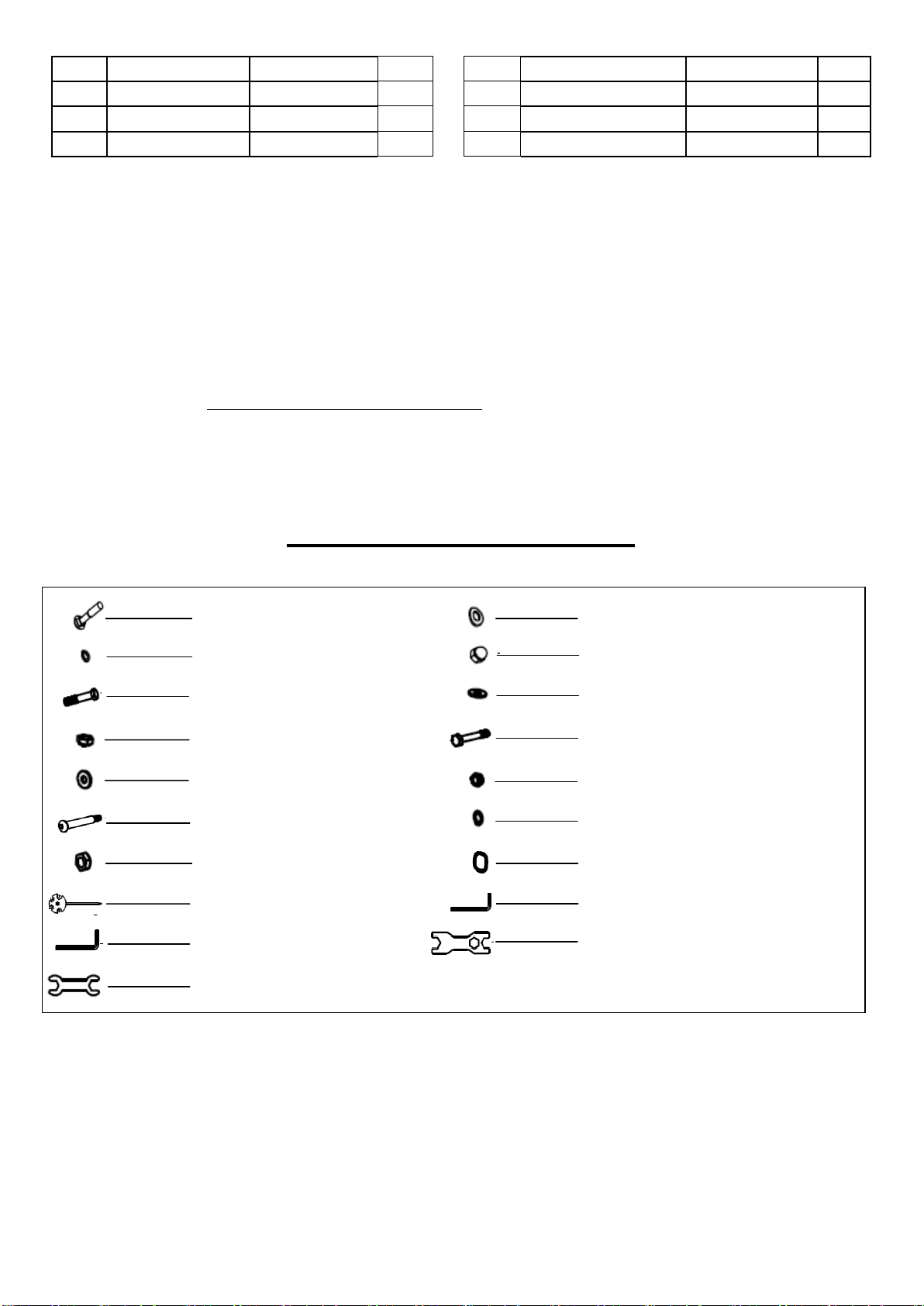
HARDWARE PACKAGE
#13 Φ20×Φ8.5×R30 4PCS
#103 S=13,14 1PC
#42 B0.5*20 2PCS
#38 Ф16x69.5 2PCS
#31 d8x1.5 2PCS
#35 M10 4PCS
#33 M10×45 4PCS
#12 M8x76 4PCS
#52 D8 4PCS
#14 M8 4PCS
#34 d10×1.5 4PCS
#30 M8×55 2PCS
#32 M8 2PCS
#41 Φ13×B2 2PCS
#45 D17×0.3 2PCS
#99 S=10,13,14,15,17 1PC
#100 S=6 1PC
#101 S=8 1PC
#102 S=17,19 1PC

5
ASSEMBLY INSTRUCTIONS
We value your experience using Sunny Health and Fitness products. For assistance with parts or
troubleshooting, please contact us at [email protected] or 1-877-90SUNNY (877-907-
8669).
STEP 1:
Attach the Front & Rear Stabilizers (No. 3
& 4) to the Main Frame (No. 1) with 4
Carriage Bolts (No. 12), 4 Spring
Washers (No. 52), 4 Arc Washers (No.
13) and 4 Acorn Nuts (No. 14). Tighten
and secure with Spanner (No. 99).
STEP 2:
Check the Tension Controller (No. 17) is
at Level 8 (highest resistance) to ensure the
cable is the longest. Connect Extension
Wire (No. 18) to Sensor Wire (No. 20) then
connect the cable of Tension Controller
(No. 17) to the hook of the Tension Cable
(No. 19) as shown in Figure A.
1. Insert eye of upper tension cable into the
cable lock.
2. Pull the tension cable so that you can
insert the cable into the gap at the top of
the metal bracket.
3. Lower the tension cable so that it sits on
the metal bracket.
Remove pre-assembled 6 Inner Hex Bolts
(No. 16), 6 Spring Washers (No. 52) and 6
Arc Washers (No. 13) from Main Frame
(No. 1), then attach the Handlebar Post
(No. 2) to the Main Frame (No. 1) with 6
Inner Hex Bolts (No. 16), 6 Spring
Washers (No. 52) and 6 Arc Washers (No.
13) that were removed. Tighten and secure
with Wrench (No. 100).
NOTE: Do not completely tighten the bolts
yet.
6
We value your experience using Sunny Health and Fitness products. For assistance with parts or
troubleshooting, please contact us at [email protected] or 1-877-90SUNNY (877-907-
8669).
STEP 3:
Remove pre-assembled 2 Hex Bolts
(No. 24), 2 Spring Washers (No. 52), 2
Flat Washers (No. 25) and 2 Wave
Washers (No. 54) from the Shaft (No.
27).
Insert the Shaft (No. 27) into the
Handlebar Post (No. 2) then insert
Wave Washer (No. 54) and attach the
Left Swing Tube (No. 6L) to the left side
of Shaft (No. 27). Next, put the other end
with Flat Washer (No. 25), Spring
Washer (No. 52) and Hex Bolt (No. 24)
that were removed onto Shaft (No. 27) to
fix the other end. Tighten and secure with
Spanner (No. 99) and Spanner (No.
103).
NOTE: Do not completely tighten the
bolts yet.
CAUTION:
Hinge Bolt (No. 38) is label L or R. Left
Nylon Nut (No. 42L) is black on the
inside and Right Nylon Nut (No. 42R)
is white on the inside.
Attach the Left Pedal Support (No. 5L) to the Left Crank (No. 22) with Left Hinge Bolt (No.
38L), Wave Washer (No. 45), Spring Washer (No. 41) and Left Nylon Nut (No. 42L). Tighten and
secure with Wrench (No. 101) and Spanner (No. 102). Please note that you must turn the Left
Hinge Bolt (No. 38L) counter-clockwise to tighten, and screw the Left Nylon Nut (No. 42L)
clockwise onto the threaded end of the Connecting Joint (No. 40L).
NOTE: Do not tighten the bolts yet.
Attach the Left Swing Tube (No. 6L) to the Left Pedal Support (No. 5L) with Hex Bolt (No. 30),
Flat Washer (No. 31) and Nylon Nut (No. 32) with Spanner (No. 99) and Spanner (No. 103).
Tighten Hex Bolt (No. 24), Hex Bolt (No. 30) and Left Nylon Nut (No. 42L) using Spanner (No.
99) and Spanner (No. 103) and cover the bolts with Caps (No. 23 & 57 & 43 & 36).
Repeat the steps above to assemble the right side, but please note that you must turn the Right
Hinge Bolt (No. 38R) clockwise to tighten, and screw the Right Nylon Nut (No. 42R) counter-
clockwise onto the threaded end of the Connecting Joint (No. 40R).
Tighten all the Inner Hex Bolts (No. 16) on the Handlebar Post (No. 2) for step 2 using Wrench
(No. 100).

7
We value your experience using Sunny Health and Fitness products. For assistance with parts or
troubleshooting, please contact us at [email protected] or 1-877-90SUNNY (877-907-
8669).
STEP 4:
Attach the 2 Pedals (10L/R) to the
corresponding 2 Pedal Supports (No.
5L/R) with 4 Hex Bolts (No. 33), 4 Flat
Washers (No. 34) and 4 Nylon Nuts
(No. 35) using Spanner (No. 102).
NOTE: There are 3 positions on the
Pedal Support (No. 5L/R), numbered 1,
2, and 3, that you can install the Pedals
(No. 10R/L). Adjust the pedal position to
suit your comfort level. Make sure both
Left and Right Pedals (No. 10 L/R) are
set at the same position numbers.
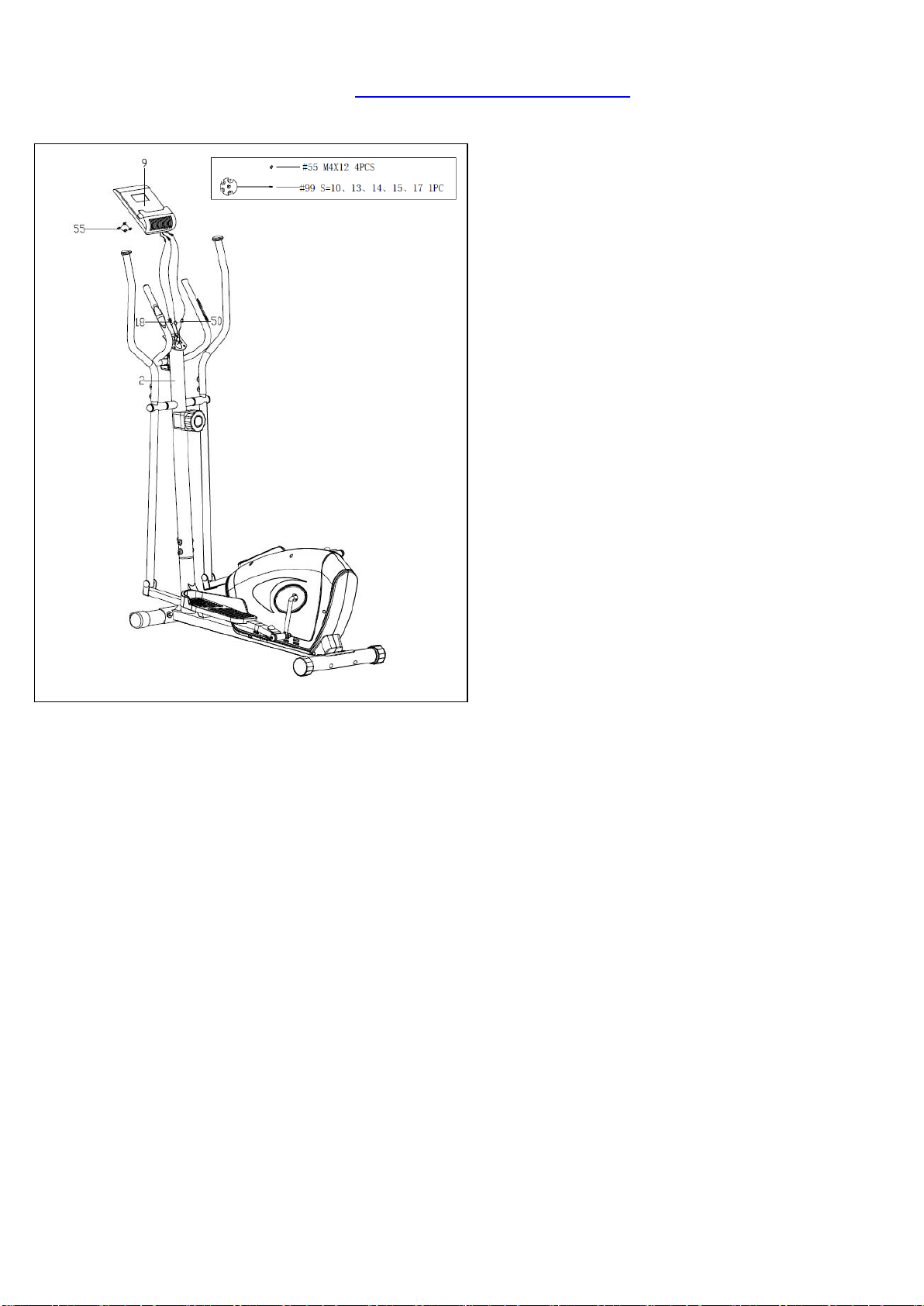
STEP 5:
Insert the Pulse Wire (No. 50) through
the hole of Handlebar Post (No. 2) then
pull it out from the hole of computer
bracket at the top of the Handlebar Post
(No. 2).
Remove pre-assembled 2 Inner Hex
Bolts (No. 51) and 2 Spring Washers
(No. 52) from the Handlebar (No. 8) first.
Attach Handlebar (No. 8) onto the
Handlebar Post (No. 2) with 2 Inner
Hex Bolts (No. 51) and 2 Spring
Washers (No. 52) that were removed
using Wrench (No. 100). Lastly, put on
the Clamp Cover (No. 53).
Remove pre-assembled 4 Inner Hex
Bolts (No. 16), 4 Spring Washers (No.
52) and 4 Arc Washers (No. 44) from
the Swing Tubes (No. 6L/R). Attach the
2 Handlebars (No. 7L/R) to the
corresponding Swing Tubes (No. 6L/R)
and secure them with 4 Inner Hex
Bolts (No. 16), 4 Spring Washers (No.
52) and 4 Arc Washers (No. 44) using
Wrench (No. 100).
8
We value your experience using Sunny Health and Fitness products. For assistance with parts or
troubleshooting, please contact us at [email protected] or 1-877-90SUNNY (877-907-
8669).
STEP 6:
Remove pre-assembled 4 Cross Pan
Head Screws (No. 55) from the back of
the Computer (No. 9). Connect
Extension Wire (No. 18) and 2 Pulse
Wires (No. 50) to the relevant wires of
the Computer (No. 9). Attach the
Computer (No. 9) to the computer
bracket of Handlebar Post (No. 2) with
4 Cross Pan Head Screws (No. 55)
using Spanner (No. 99).
Now, make sure you completely tighten
all the bolts and screws from the previous
steps.
The assembly is complete!
9
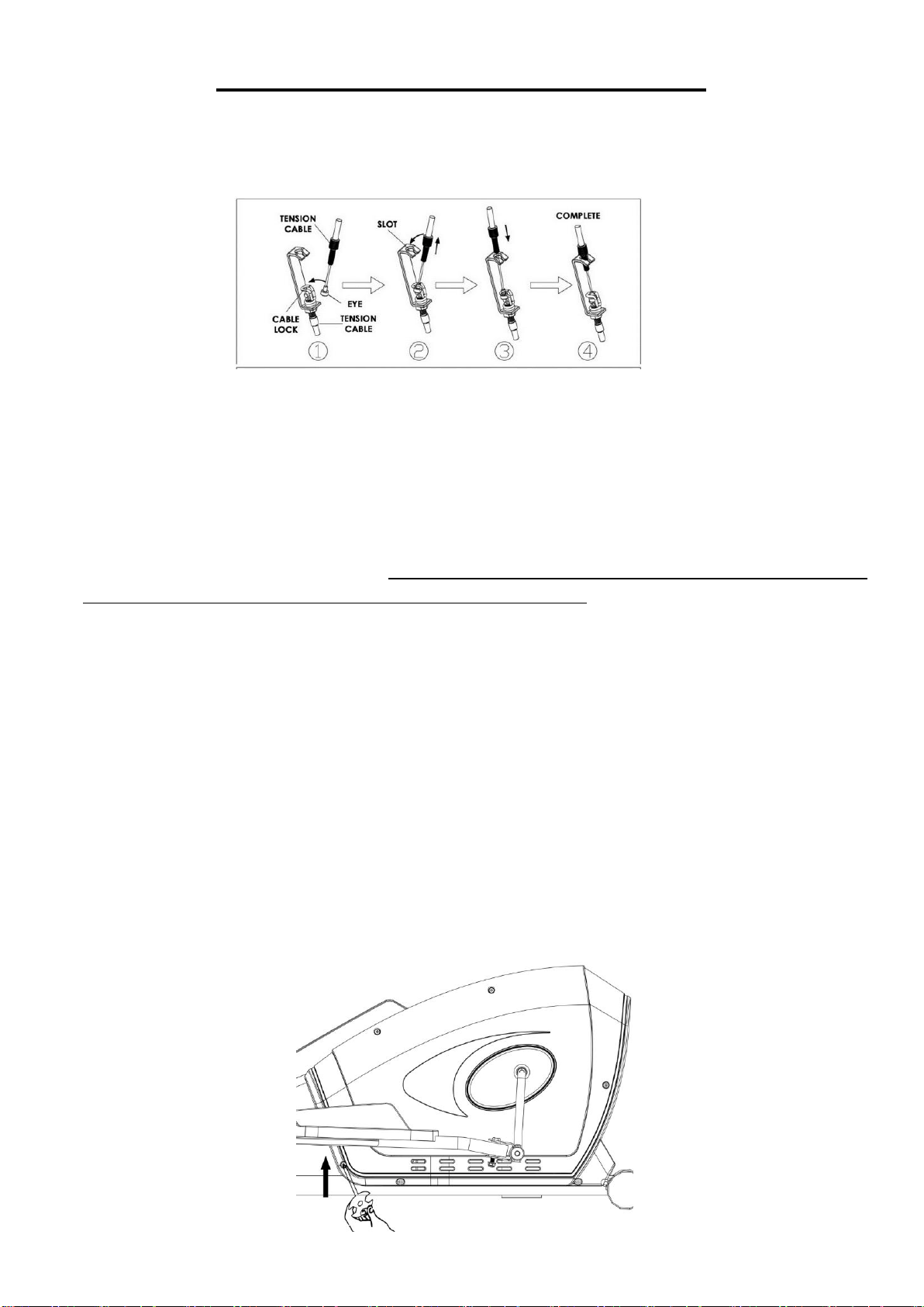
ADJUSTMENTS & USAGE GUIDE
1. If you find there is no difference between tension level 1 to level 8, check the connection of the
tension cable. See Diagram below.
2. If the computer does not show numbers correctly, check the batteries. If the computer does not
count the speed and time, check the connections of Extension Wire (No. 18) to the Computer
(No. 9) and Extension Wire (No. 18) to Sensor Wire (No. 20).
3. If you have difficulty putting Hinge Bolts (No. 38L/R) into the Crank (No. 22), try moving the
Crank (No. 22) to a different angle. Keep in mind the Left Hinge Bolt (No. 38L) has reverse
threading and must be installed by turning counter-clockwise.
4. If you hear any noise when using the machine, please check if Hinge Bolts (No. 38L/R), Hex
Bolt (No. 30), Hex Bolt (No. 24) and Connecting Joint (No. 40) are loose. You may remove
these parts and add some lubricant oil to eliminate all noise possibilities, remember to tighten
all the parts securely.
5. When you first use the machine, if you hear any unusual noises from the inside of the Belt
Cover (No. 66L/R), please loosen the screws on the chain cover about two rotations, then
push the Belt Cover (No. 66L/R) up a little bit; finally, fasten the screws you loosened before.
See the following diagram. (During shipping, the Belt Cover (No. 66L/R) can be dislocated,
and the Flywheel (No. 96) may rub on the Belt Cover (No. 66L/R).

10
6. If it is very hard to pedal on the higher tension levels, or you hear rubbing noises, please
remove the Belt Cover (No. 66L/R), and adjust the screw seen in the following diagram. You
will need to lower the position of the screw by turning counter-clockwise; this will keep the
Magnetic Board (No. 89) from contacting the magnetic flywheel. Before re-installing the Belt
Cover (No. 66L/R), test the tension level 8 to ensure the magnets do not touch the flywheel.
。
7. If you still hear noises after you did Step 5 and Step 6, please remove the Belt Cover (No.
66L/R); loosen the screws for the Flywheel (No. 96) about a half of a rotation. See the
following diagram.
8. If you feel the machine is uneven, please adjust the Rear End Cap (No. 15) on Real Stabilizer
(No. 4) by turning it. If the machine is wobbly when you use it, please consider adding an
exercise mat under it.
11
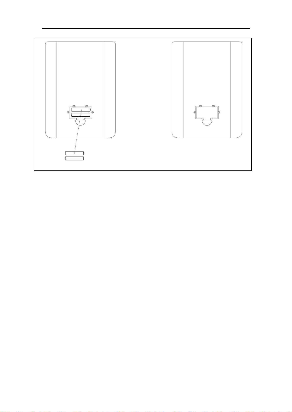
BATTERY INSTALLATION & REPLACEMENT
BATTERY INSTALLATION:
The computer uses 2 AA batteries. Open the battery cover from the back of the computer, then
put 2 batteries into the battery compartment. Make sure the (+) and (-) ends of the batteries are
in the correct position. Put the battery cover back.
BATTERY REPLACEMENT:
If there is a problem with the display, try changing the batteries first. Open the battery cover,
remove the old batteries and replace with new batteries. Make sure the (+) and (-) ends of the
batteries are in the correct position. Put the battery cover back.
When changing batteries, always replace both with new batteries. Do not mix old and new
batteries.
12
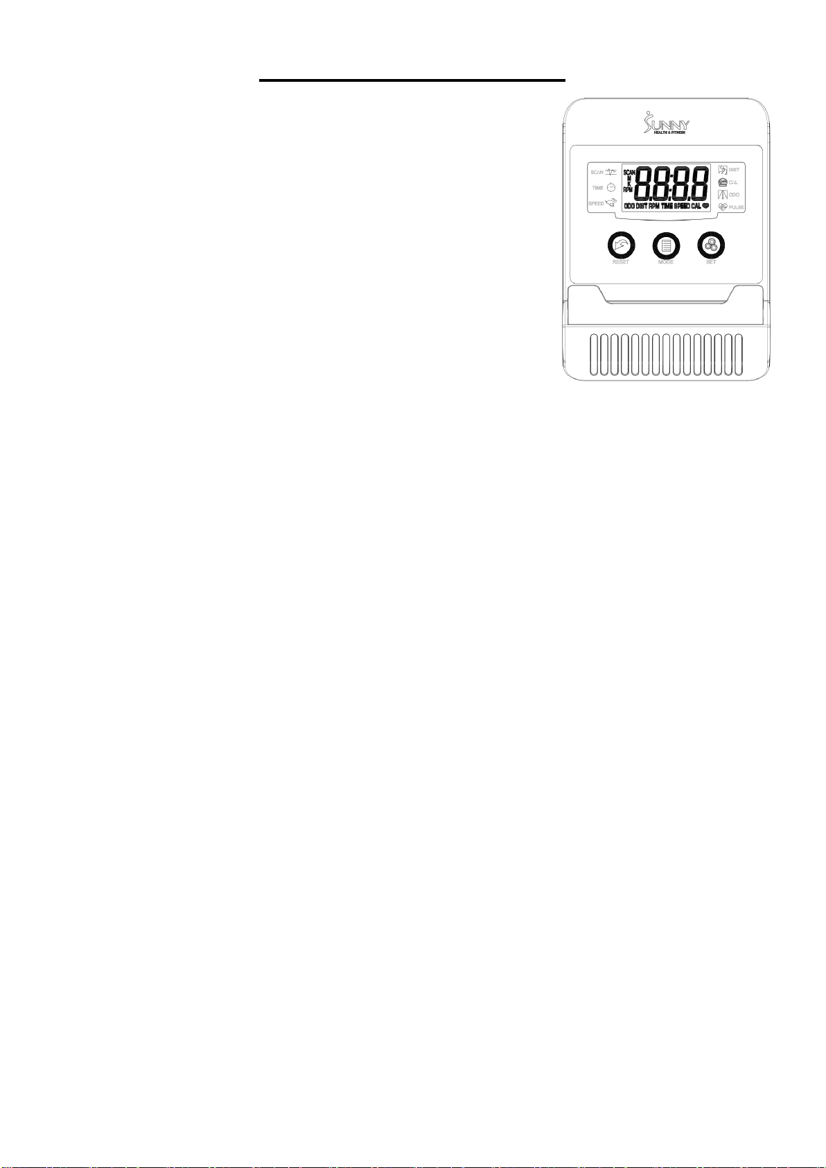
EXERCISE COMPUTER
SPECIFICATIONS:
TIME.………………………………..00:00-99:59 MIN:SEC
SPEED.………………………………………0.0-999.9 MPH
DISTANCE.………………………………0.00-99.99 MILES
CALORIES.………………….……………...0.0-999.9 KCAL
ODOMETER………………………………..0.0-9999 MILES
PULSE.………………………………................40-240 BPM
FUNCTION KEY:
MODE: Press to select function.
RESET: Press to reset the value back to zero.
SET: Press to preset the desired countdown of TIME, DISTANCE,
or CALORIES.
OPERATION PROCEDURES:
1. AUTO ON/OFF:
If the elliptical is put into motion or the MODE button is pressed, the computer will turn on.
After 4 minutes of inactivity, the computer will turn off.
2. RESET:
The computer can be reset by pressing and holding the MODE button for three seconds.
Removing the batteries will also reset the computer and change all function values back to zero.
3. MODE:
To select the LOCK MODE setting press the MODE key when the pointer on the function you wish
to select begins to blink (once locked only the selected function will be displayed).
4. FUNCTIONS:
TIME: Counts the total time of an exercise session from start to finish.
SPEED: Displays the current speed.
DISTANCE: Counts the total distance of an exercise session from start to finish.
CALORIES: Counts the total amount of calories burned during an exercise session from start to
finish.
ODOMETER: Counts the total distance traveled from all workout sessions.
PULSE: Displays the user’s current heart rate in beats per minute.
Place the palms of your hands on both of the pulse sensors, the computer will display your current
heart beat rate on the computer. (This value is not intended for medical use)
SCAN: Automatically displays all functions repeatedly.
Battery: The computer uses 2 AA batteries, which are packed with the computer box. Dispose the
batteries according to the laws and regulations of your local region. Some batteries may be
recycled. When disposing or recycling, do not mix battery types.
Version 1.8

13

14