Loading ...
Loading ...
Loading ...
10
P5 Stereo Control Amplifier
Cables
Be sure to keep the power cords, digital signal cables and regular audio signal
cables in your installation away from each other. This will minimize the chance
of the regular audio signal cables picking up noise or interference from the
power cords or digital cables. Using only high quality, shielded cables will also
help to prevent noise or interference from degrading the sound quality of your
system. If you have any questions see your authorized Michi dealer for advice
about the best cable to use with your system.
The RR-RH6 Remote Control
Operations with the remote control are described in this manual showing the
function keys with encircled letters.
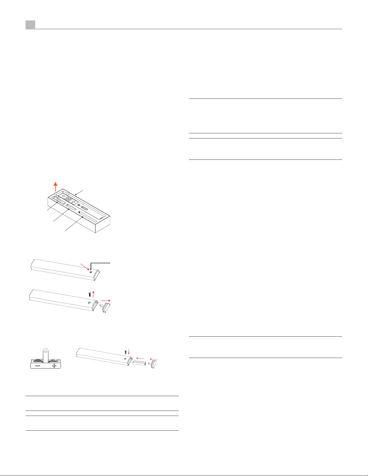
Remote Control Batteries
Two AAA size batteries must be installed before the remote control can be
used. To install the batteries, follow the steps as below:
1. Lift the ribbon under the remote control and remove it out of the box.
Remote Control
Battery
(if included)
Hex Tool
USB Flash Drive
2. Remove the screw on the back of the remote using the hex tool provided
with the remote. Use only the hex tool supplied to avoid damaging the
attaching screw.
3. Install the batteries as shown in the illustration in the battery well (Figure
2). Please note there are negative and positive marks shown on the battery
cover (Figure 1). Reassemble the battery cover and tighten the screw then
test the control for proper operation.
Figure 1 Figure 2
When the batteries become weak the remote control won’t operate the device
consistently. Installing fresh batteries should eliminate the problem.
NOTE: Use only the tool supplied with the unit to remove the screw to
avoid damage to the hex screw.
NOTE: Do NOT over-tighten the screw to avoid damage to the screw or
remote control.
AC Power and Control
AC Power Input
a
Your P5 is configured at the factory for the proper AC line voltage in the
country where you purchased it (either 120 volts AC or 230 volts AC with a
line frequency of either 50 Hz or 60 Hz). The AC line configuration is noted
on a decal on the back panel.
NOTE: Should you move your unit to another country, it may be possible to
reconfigure it for use on a different line voltage. Do not attempt to perform
this conversion yourself. Opening the enclosure of the unit exposes you
to dangerous voltages. Consult a qualified service person or the Michi
factory service department for information.
NOTE: Some products are intended for sale in more than one country
and as such are supplied with more than one AC cord. Please only use
the one appropriate for your country/region.
The P5 should be plugged directly into a 2-pin polarized wall outlet. Do not
use an extension cord. A heavy duty multi-tap power outlet strip may be used
if it (and the wall outlet) is rated to handle the current demanded by the P5
and all the other components connected to it.
If you are going to be away from home for an extended period of time such
as a month long vacation, it is a sensible precaution to unplug the P5 (as well
as other audio and video components) while you are away.
Master Power Switch
s
The large rocker switch on the rear panel is a master power switch. When it is
in the OFF position, power to the unit is completely off. When it is in the ON
position, the front panel POWER
5
and remote control Standby button
A
can be used to activate the unit or put it into standby mode.
12V TRIGGER Connection
p
See Figure 5
Some audio components can be turned on automatically when they receive a
12V turn on “signal”. The two 12V Trigger Outputs on the P5 provide the required
signal. Connect compatible components to the P5 with a conventional 3.5
mm mini mono plug cable. When the P5 is in standby mode, the trigger signal
is disabled, so the components controlled by it will be turned off.
Input Signal Connections
NOTE: To prevent loud noises that neither you nor your speakers will
appreciate, make sure the system is turned off when you make any signal
connections.
Phono Input
8
and Ground Connection (GND)
r
See Figure 3
Plug the cable from the turntable into the appropriate left and right phono
inputs. If the turntable has a “ground” wire, connect it to the screw terminal
to the left of the Phono inputs. This will help prevent hum and noise.
Loading ...
Loading ...
Loading ...