Loading ...
Loading ...
Loading ...
Part number 550-142-054/1211
GV90+ gas-fired water boiler — Boiler Manual
18
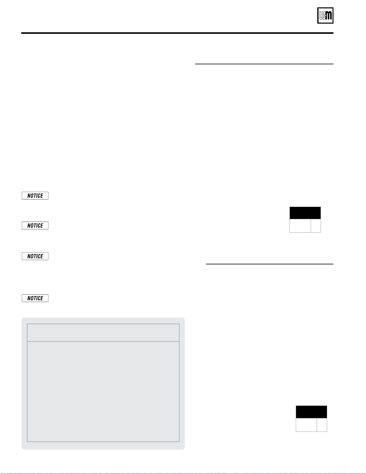
Figure 20 Radiator system — zone-valve zoning
Figure 21 Radiator system — circulator zoning
Radiator system piping
Apply Figure 20 (zone-valve zoning) or Figure 21 (circulator zoning)
to systems using standing cast iron radiators. This applies to gravity
water systems and converted steam systems using columnar, tubular
or recessed cast iron radiators.
The suggested piping for zone-valve zoning radiator systems differs
from baseboard systems because of the high water content of cast iron
radiators. The GV90+ internal circulators automatically regulate supply
and internal bypass flow based on the temperature of the water return-
ing to the boiler. At the start of many heating cycles in a radiator system,
the water in the radiators is cool. So the boiler would slow down system
flow rate while sending out relatively hot water. This could cause heat
distribution problems. Install a separate system circulator as shown
in Figure 20 when zoning with zone valves. The separate circulator
assures a relatively constant temperature drop through the system.
The boiler internal circulators must be left in the boiler. They cannot
be removed for use a zoning circulator. Provide a circulator for each
zone when circulator zoning, and pipe the system as in Figure 21.
Balancing, when required
—
Substitute a memory-stop
valve for one of the isolation valves in each zone to use
the memory-stop valve for balancing flow as well as
isolation.
Zoning with zone valves —
Provide a separate 24-volt
transformer to power the zone valves. Size the trans-
former to handle the total rated load of all connected zone
valves. Alternatively, use a zone valve zone controller.
Zoning with circulators — The GV90+ internal system
circulator cannot be removed from the boiler for use as
one of the zone circulators. It must remain as shipped
from the factory to allow proper flow control inside the
boiler. You will need a circulator for each zone. Provide
circulator relays or circulator zone controller.
The system circulator must be supplied by the in-
staller.
MINIMUM
Boiler loop pipe size
GV90+3/4
GV90+5/6
1”
1¼”
MINIMUM
Boiler loop pipe size
GV90+3/4
GV90+5/6
1”
1¼”
Legend
1 Isolation valves
2 Automatic air vent (with diaphragm-type expansion tank), or
connect to tank fitting (closed-type expansion tank).
3 Diaphragm- or bladder-type expansion tank, if used. (For closed-
type expansion tank, pipe from top of air separator to tank fitting
as in Figure 15, page 14.)
4 Zone valve
5 System or zone circulator
6 Flow/check valve
7 Hose bibb purge valve
8 Boiler pressure/temperature gauge
9 System supply temperature gauge
10 Differential pressure by-pass valve
16 Cold water fill line — see Figure 15, page 14 for typical components
Install water piping (continued)
(0ptional)
Loading ...
Loading ...
Loading ...