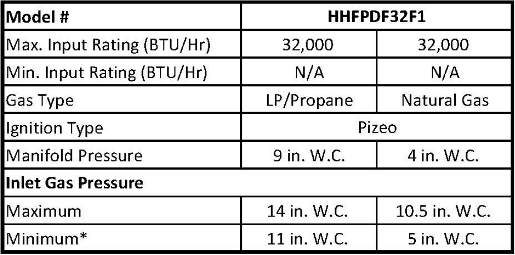
The heater is equipped to operate on either propane or natural gas. The heater is shipped from the factory ready for connecting to propane. The heater can easily be changed to natural gas by having your qualified installer follow the instructions on page 18 and the markings on the heater.
SAFETY PILOT
This heater has an Oxygen Depletion Sensing (ODS) safety shutoff system pilot. The ODS/pilot shuts off the heater if there is not enough fresh air and cuts off the main burner gas in the event of flame out.
HANDHELD REMOTE WITH THERMOSTAT HEAT CONTROL
The thermostat control automatically cycles the burner on and off to maintain a desired room temperature. See page 26.
Optional BLOWER MODEL HHFAN100
The blower has 3 settings ON/OFF/Auto which helps to distribute the warmed air into the space more rapidly. NOTE: This is an optional accessory and is not required for operation of the heater.
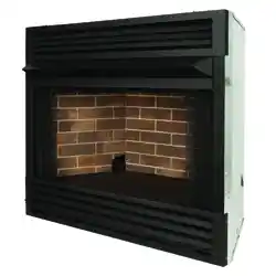
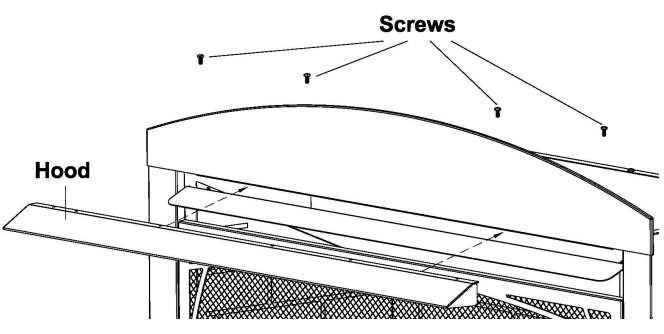
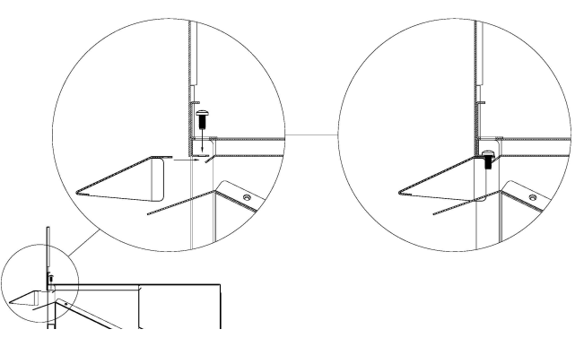
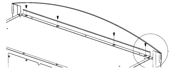
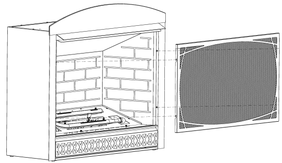
Hood Assembly to Fireplace
Secure hood to fireplace with four screws provided as shown.
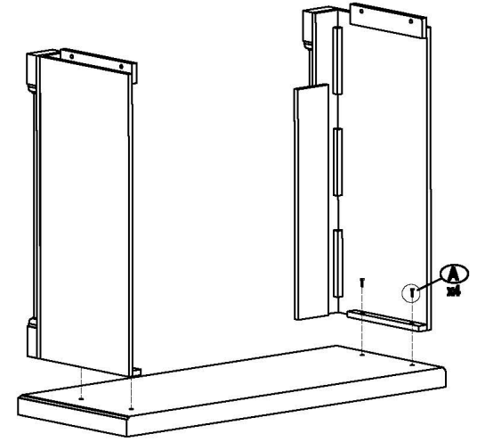
Mantel Assembly
1. Carefully align mounting holes in mantel sides over threaded inserts in mantel base. Secure mantel sides to mantel base with the four screws (two per side) as shown. Do not fully tighten until after final assembly
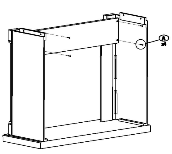
2. Carefully align mounting holes in mantel front over threaded inserts in mantel sides. Secure mantel front to mantel sides with the four screws (two per side) as shown. Do not fully tighten until after final assembly
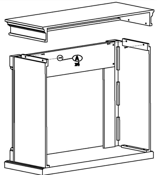
3. Carefully set Mantel top onto mantel sides aligning mounting holes in mantel sides with threaded inserts in the mantel top. Secure mantel top with the four screws (two per side) as shown. Fully tighten all 12 screws to complete the mantel assembly.
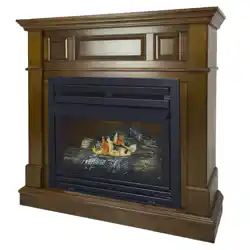
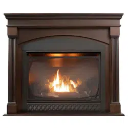
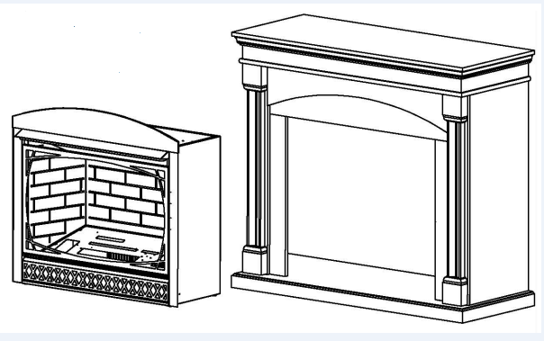
Fireplace to Mantel Assembly
Carefully lift the fireplace through the center opening in the front of the fireplace mantel. Slide the fireplace through the opening until the metal trim contacts the front of fireplace mantel.
General Preparation
LOCAL CODES
Install and use the heater with care. Follow all local codes. The installation must conform with local codes or, In the absence of local codes, with the latest edition of The National Fuel Gas Code, ANS Z223.1/NFPA 54*.
*Available from: American National Standard Institute, Inc. 1430 Broadway New York, NY 10018
National Fire Protection Association, Inc. 1 Batterymarch Park Quincy, MA 02269-9101
Preparing for Installation
WATER VAPOR IS A BY-PRODUCT OF UNVENTED ROOM HEATERS
Gas combustion creates water vapor as a by-product. Unvented room heaters create about one (1) ounce (30 ml) of water for every 1,000 BTUs (0.3 kW) of gas input per hour. An unvented room heater is recommended as a supplemental heat source for a single room rather than as a primary heat source for an entire house. The water vapor does not typically create a problem. In most cases, the water vapor enhances the low humidity conditions that are typical of cold weather.
Keep these points in mind so that the water vapor does not create a problem:
• The heater must be the proper size for the application. Provide adequate combustion air and circulation air.
• In humid environments, use a dehumidifier o help lower the amount of water vapor in the air.
• Do not use an unvented room heater as your primary heat source.
AIR FOR COMBUSTION AND VENTILATION
This heater shall not be installed in a room or space unless the required volume of indoor combustion air is provided by the method described in the National Fuel Gas Code, ANS Z223.1/NFPA 54, the International Fuel Gas Code, or applicable local codes.
PRODUCING ADEQUATE VENTILATION
Spaces in homes can be divided into these ventilation classifications:
• Unusually Tight Construction
• Unconfined Space
• Confined Space
The information on pages 10–12 will help you classify your space and provide adequate ventilation.
Confined and Unconfined Space:
A confined space has a volume less than 50 cu. ft. per 1,000 BTU/hr (4.8 m3 per kW) of the total input rating of all appliances installed in that space. An unconfined space has a volume not less than 50 cu. ft. per 1,000 BTU/hr (4.8 m3 per kW) of the total input rating of all appliances installed in that space. Rooms that are directly connected to the space in which the appliances are installed*, through openings that do not have doors, are considered a part of the unconfined space. Do not install this heater in a confined space or unusually tight construction unless you provide provisions for adequate combustion and ventilation air.
*Adjoining rooms are directly connected only if there are doorless passageways or ventilation grills between them.
Unusually Tight Construction:
Doors and windows may leak air that provides enough fresh air for combustion and ventilation. However, you must provide additional fresh air in buildings of unusually tight construction. Unusually tight construction is defined as construction that meets the following criteria:
A. Walls and ceilings exposed to the outside atmosphere have a continuous water vapor retarder with a rating of one perm (6x10-11kg per pa-sec-m2) or less with openings that are gasketed or sealed.
B. Doors and windows that can be opened have weather stripping.
C. Caulking or sealants are applied to areas such as joints around window and door frames; between sole plates and floors; be ween wall-ceiling joints; between wall panels; at penetrations for plumbing, electrical, and gas lines; and at other openings.
If your residence meets all the above criteria, additional fresh air must be provided. See VENTILATION AIR FROM OUTDOORS on page 10 for more information. If your residence does not meet those three criteria, continue to DETERMINING FRESH-AIR FLOW FOR THE HEATER LOCATION.
DETERMINING FRESH-AIR FLOW FOR THE HEATER LOCATION
Determining if You Have a Confined or Unconfined Space:
Use the below information to determine if you have a confined or unconfined space. Your space includes the room in which you will install the heater plus any other rooms that are directly connected and have doorless passageways or ventilation grills between the rooms.
1. Determine the volume of the space. Length × Width × Height = cu. ft. (volume of space) • Example: 20 ft. (length) × 16 ft. (width) × 8 ft. (ceiling height) = 2560 cu. ft. (volume of space) If additional ventilation to adjoining room(s) is supplied with grills or openings, add the volume of these rooms to the total volume of your space.
2. Divide the space’s volume by 50 cu. ft. to determine the maximum BTU/hr the space can support. _______ (volume of space) ÷ 50 cu. ft. = (maximum BTU/hr the space can support)
• Example: 2560 cu. ft. (volume of space) ÷ 50 cu. ft. = 51.2 or 51,200 (maximum BTU/hr the space can support)
3. Add the BTU/hr of all fuel burning appliances in the space: Example: Gas heater __________BTU/hr Gas water heater 40,000 BTU/hr Other gas appliances*+ ____BTU/hr Vent-free heater + 30,000 BTU/hr Total = ____BTU/hr Total = 70,000 BTU/hr
*Do not include direct-vent gas appliances. Direct-vent appliances draw combustion air from outdoors and vent to the outdoors.
4. Compare the maximum BTU/hr the space can support with the actual amount of BTU/hr used: _______ BTU/hr (maximum the space can support) _______ BTU/hr (actual amount of BTU/hr used).
• Example : 51,200 BTU/hr (maximum the space can support) 70,000 BTU/hr (actual amount of BTU/hr used) The space in the above example is a confined space because the actual BTU/hr used is more than the maximum BTU/hr the space can support. You must provide additional fresh air. Your options are as follows:
A. Add the space of an adjoining room and rework the above information. If the extra space creates an unconfined space, remove the door to the adjoining room or add ventilation grills between rooms. See VENTILATION AIR FROM INSIDE A BUILDING, page 10.
B. Vent the room directly to the outdoors. See VENTILATION AIR FROM OUTDOORS, page 10.
C. Install a heater that uses less BTUs/hr if the lower BTUs/hr creates an unconfined space. If the actual BTU/ hr used is less than the maximum BTU/hr the space can support, the space is an unconfined space. In this case, no additional fresh air ventilation is needed.
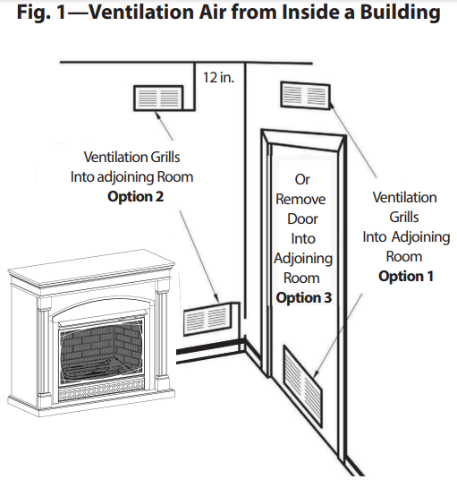
VENTILATION AIR FROM INSIDE A BUILDING
Fresh air comes from a connected unconfined space. You must provide two permanent openings when ventilating to a connected unconfined space, one of which that’s within 12" of the wall that connects the two spaces (see options 1 and 2, Fig. 1). You may also remove the door into the adjoining room (see option 3, Fig. 1). Follow the National Fuel Gas Code NFPA 54/ANS Z223.1 for the required size of ventilation grills or ducts.
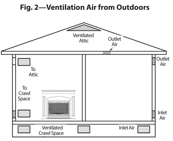
VENTILATION AIR FROM OUTDOORS
Extra fresh air is provided via ventilation grills or ducts. You must provide two permanent openings: one within 12" of the ceiling and one within 12" of the floor (see Fig. 2). They must connect directly to the outdoors or spaces that open to the outdoors. Such spaces may include attics or crawl spaces. Follow the National Fuel Gas Code NFPA 54/ANS Z223.1 for the required size of ventilation grills or ducts.
Installation
POSITIONING THE FIREPLACE HEATER
This Fireplace Heater with mantel sets on the floor. For convenience and efficiency, install the heater as follows:
• In a location with easy access for operation, inspection, and service.
• In the coldest part of the room.
• A minimum of 3' (36") away from furniture and draperies.
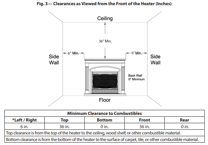
HEATER CLEARANCES
For convenience and efficiency, install the heater with these points in mind:
• Provide easy access for operation, inspection and service.
• Install the heater in the coldest part of the room. If this heater is installed directly on carpeting, tile, or other combustible material, other than wood flooring, the heater must be installed on a metal or wood panel that extends the heater’s full width and depth.
INSTALLING THE HHFAN100 BLOWER (OPTIONAL)
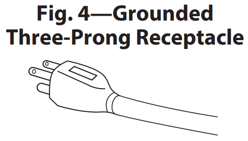
WARNING : Electrical grounding instructions: This appliance is equipped with a three-prong (grounding) plug for your protection against shock hazard and should be plugged directly into a properly grounded three-prong receptacle (See Fig. 4).
Disconnect heater from the gas supply before installing the fan accessory. Contact a qualified service person to do this.
1. Remove the blower panel using a screwdriver (see Fig. 5).
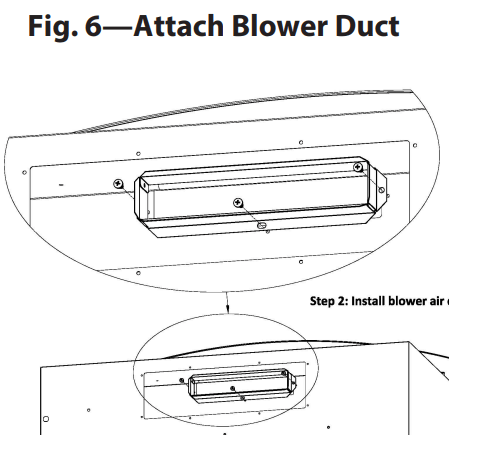
2. Attach blower duct to the rear panel of the heater using three screws provided (see Fig. 6).
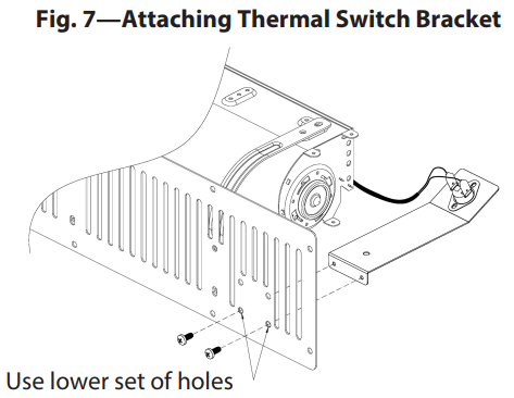
3. Attach blower thermal switch bracket to blower panel with two screws provided. Note the bracket attaches to the upper set of holes (see Fig. 7).
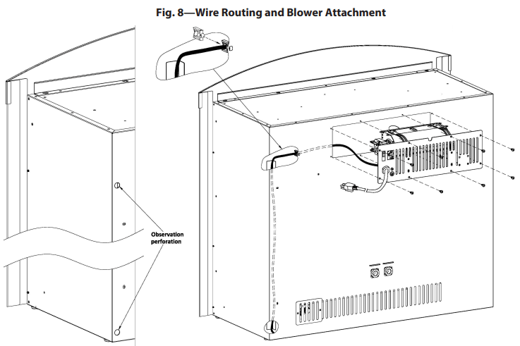
4. Route wire harness through channel in the back corner of the fireplace. There are two observation ports on the back of the fireplace to assist in routing the wire harness. Before securing blower assembly to the fireplace, put a wire clip on wire harness and snap into the inside of the fireplace back panel. Secure blower with 8 screws (see Fig. 8).
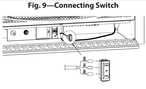
5. Route the wire harness as shown through the opening in the control panel. Connect the wires to the switch in the order identified in the wiring diagram (see Fig. 9).
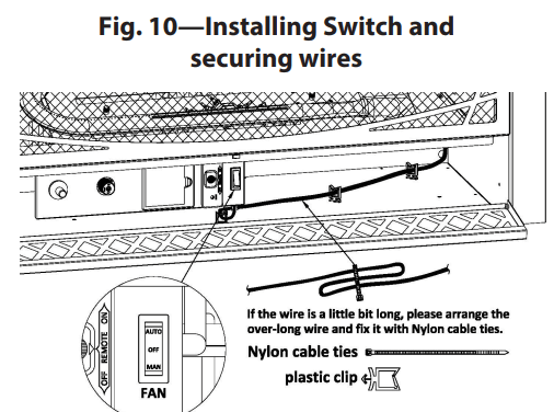
6. Snap Switch into opening in control panel, making sure to position the Auto function on top. Wire clips and a cable tie are provided to help keep the wire harness away from the hot firebox and burner (see Fig. 10).
The Blower is equipped with manual ON, OFF and AUTO switch (see Fig. 8). In the Auto position the Blower will automatically come on a few minutes after the burner comes on and will shut off a few minutes after the burner shuts off.
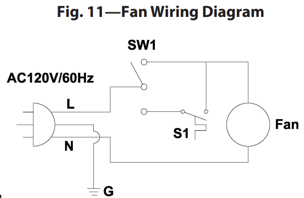
NOTE: If any of the original wire supplied with the heater must be replaced, a wire of at least an equal temperature rating must be used. Refer to Fig. 11 for the wiring diagram.
GAS SELECTION INSTRUCTIONS
CAUTION: The knob to the gas selection means shall not be accessed or adjusted while the appliance is in operation.
CAUTION: Two gas line installations at the same time are prohibited. The access plate to simple switching means shall not be opened while heater is in operation. Installation and adjustments shall be made by a qualified technician only.
NOTE: If you are connecting this appliance to propane do not make any adjustments. Proceed to installing the gas line as instructed in the Owner’s Manual.
Convert to natural gas:
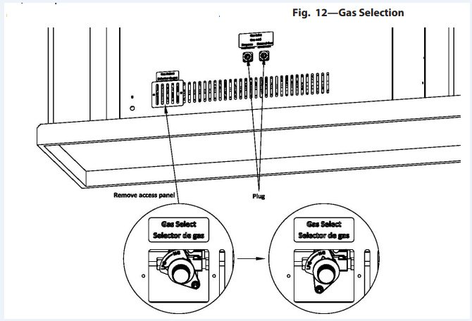
Step 1 - Remove access panel WARNING: This appliance can be used with propane or natural gas. It is shipped from the factory adjusted for use with propane.
Step 2 - Adjust the gas selector valve Push in on the selector valve Knob and rotate the knob clockwise until it stops. Release the knob (See Fig. 12)
Do not operate the appliance between locked positions.
Step 3 - Replace Access Panel
Reverse step 2 to convert back to propane gas.
CONNECTING TO A GAS SUPPLY
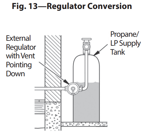
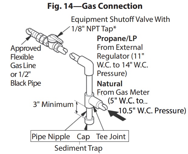
The installer must supply an external regulator for liquid propane. For natural gas, the gas supplier supplies the external regulator. The external regulator reduces incoming gas pressure, and the pressure must be reduced to between 11" and 14" of water column for propane and between 5" and 10.5" of water column for natural gas. Heater regulator damage could occur if the pressure of the incoming gas is not reduced. Install the external regulator with the vent pointing down as shown in Fig. 13. The purpose of pointing the vent down is to protect it from freezing rain or sleet.
*The equipment shutoff valve can be purchased from your local home center store.
INSTALLATION ITEMS NEEDED (NOT PROVIDED):
• 8" Pipe Wrench
• 8" Adjustable Wrench
• Shutoff Valve
• 3/8" Flexible Gas Line (24" Min.) or 1/2" Black Pipe
• 90 Deg. 3/8 NPT x 3/8" Flare Fitting or 3/8" Street Elbow
• Sealant (Resistant to natural or propane/LP gas)
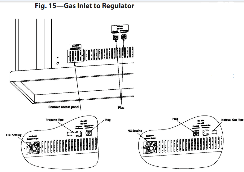
1.Depending on where your gas supply line is located, a variety of options are possible for routing the gas connection lines. First remove the plug from the regulator for the type of fuel you're using. Install a 3/8" NPT fitting to the heater regulator using sealant. Use of a 90 degree elbow will allow for the minimum clearance to a wall.
NOTICE: Most building codes do not permit concealed gas connections. Check your local building code before using a flexible gas line for this installation.
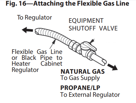
2. Install the gas line to the fitting, and attach it to the shutoff valve (see Fig. 15 & 16). Depending on your connection, it might be necessary to cut and access the hole in the side or bottom of the mantel cabinet.
3. Check all connections for gas leaks.
CHECKING GAS CONNECTIONS
Pressure Testing Gas Supply Piping System Test Pressures in Excess Of 1/2 PSIG (3.5 kPa):
1. Disconnect the heater, including the main gas valve (control valve) and equipment shutoff valve, from the gas supply piping system. Pressures greater than 1/2 PSIG will damage the regulator.
2. Cap off the open end of the gas pipe where the equipment shutoff valve was connected.
3. Open the gas supply tank valve or use compressed air to pressurize the supply piping system.
4. Check all joints of the gas supply piping system. Use a mixture of liquid soap and water in the gas joints to check for leaks—bubbles may indicate a leak.
5. Immediately correct all leaks.
6. Reconnect the heater and equipment shutoff valve to gas supply. Check reconnected fittings or leaks.
Test Pressures Equal To or Less Than 1/2 PSIG (3.5 kPa):
1. Close the equipment shutoff valve (see Fig. 16).
2. Open the gas supply tank valve or use compressed air to pressurize the supply piping system.
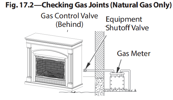
3. Check all joints from the gas meter to the equipment shutoff valve (see Fig. 16.1 & 16.2).
4. Use a mixture of liquid soap and water in the gas joints to check for leaks—bubbles may indicate a leak.
5. Immediately correct all leaks.
Pressure Testing Heater Gas Connections:
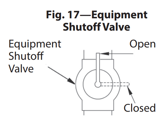
1. Open the equipment shutoff valve (see Fig. 17).
2. Open the gas supply tank valve.
3. Ensure the control knob of the heater is in the OFF position.
4. Check all joints from the equipment shutoff valve to the control valve (see Fig. 17.1 & 17.2). Use a mixture of liquid soap and water in the gas joints to check for leaks—bubbles may indicate a leak.
5. Light the heater (see OPERATION, pages 23–24). Check all other internal joints for leaks.
6. Turn off the heater (see TO TURN OFF GAS TO THE HEATER, page 24
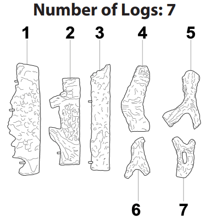
Log Placement
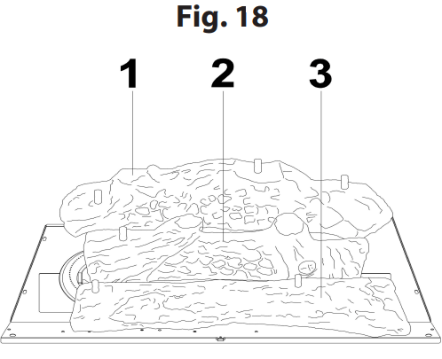
Install the logs exactly as indicated (see Fig. 18 & 19). Do not modify the logs, and use only logs supplied with the heater. The logs are numbered and correspond to the numbers listed below.
1.Place log #1 on pins behind the burner Place log #2 on pins between burners and log #3 on pins in front of burner.
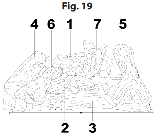
2.. Place log #4 onto pins in log #1. Place log #5 onto pins in log #1 and #3. Place log #6 onto pins in logs #2 and #3. Place log #7 onto pins in logs #1 and #2.
After installing the logs, attach screen by hooking the slots on the ends of the screen on the pins in the side of the fireplace. Note, logs are not shown for clarity.
Operation
LIGHTING INSTRUCTIONS
1.STOP! Read all the above safety information before proceeding.
2.Open the Lower Access Panel located below the heater screen.
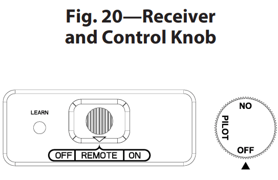
3.Set the receiver switch to the “ON” position (see Fig. 20).
4.Turn the control knob clockwise to the “OFF” position (see Fig. 20).
5.Wait five (5) minutes to clear out any gas. Then smell for gas, including near the floor. If you smell gas, STOP! Follow “B” in the safety information above. If you don’t smell gas, go to the next step.
6.Push in slightly and turn the control knob counterclockwise to the “PILOT” position (see Fig. 20). Depress the control knob.
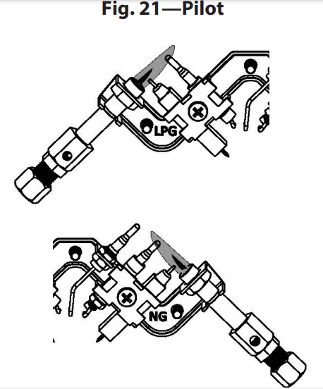
7.With the control knob depressed, push down on the ignitor button until the pilot lights. The pilot is located behind log #3 near the center of the burner (see Fig. 21).
8.Keep the control knob depressed for (30) seconds after the pilot lights. Release the control knob.
• If the control knob does not pop up when released, stop and immediately call a qualified service technician or gas supplier.
• If the pilot goes out, repeat steps 3 through 7. Wait (1) minute before attempting to light the pilot again. If after several tries the pilot still goes out, turn the gas control knob clockwise to the “OFF” position and call a qualified service technician
9.Turn the control knob counterclockwise to the “ON” position.
10. Close the Lower Access Panel.
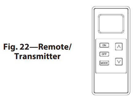
11. To use the included thermostatic remote control, set the receiver switch to the “REMOTE” position (see Fig. 20). Press the “ON” button to turn on the remote (Fig. 22) to ignite the main burner. Refer to the remote control instruction manual on page 26 for the “MODE” and “SET” functions.
TO TURN OFF GAS TO THE HEATER
1. Set the thermostat to the lowest setting.
2. Press the “OFF” button on the remote control.
3. Push in slightly and turn the control knob clockwise o the “OFF” position.
INSPECTING BURNERS
Check the pilot flame pattern and burner flame patterns often.
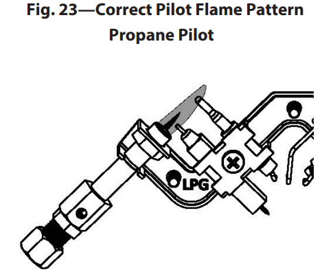
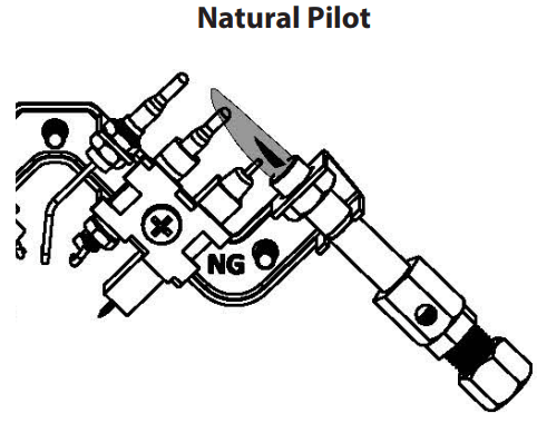
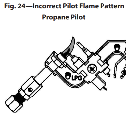
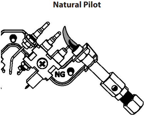
PILOT FLAME PATTERN
Figure 23 shows a correct pilot flame pattern. Figure 24 shows an incorrect pilot flame pattern. The incorrect pilot flame is not touching the thermocouple. This will cause the thermocouple to cool. When the thermocouple cools, the heater will shut down. If pilot flame pattern is incorrect, as shown in Figure 24:
• Turn the heater off (see TO TURN OFF GAS TO THE HEATER, pages 24).
• See the TROUBLESHOOTING GUIDE, page 34.
Remote Control Operation
This remote control system was developed to provide a convenient, user-friendly, and safe remote control system for gas heating appliances. The system is operated manually from the remote/transmitter and operates on radio frequencies (RF) within a 20-foot range using non-directional signals. The system uses one of 16777216 security codes that are programmed into the remote/transmitter at the factory. The remote receiver’s code must be matched to the transmitter’s code prior to initial use.
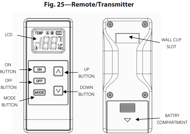
This remote control system provides you with a battery-operated remote control to power the gas valve. (see Fig. 25).
Using the battery power from the receiver, the solenoid circuit operates a solenoid. The circuit uses reversing polarity software to reverse the positive (+) and negative (-) output of the receiver’s battery power, which drives a latching solenoid ON/OFF. The system is controlled by the remote/transmitter, which operates on two (2) 1.5 V AAA batteries.
Always use ALKALINE batteries for longer battery life and maximum performance. Do not use rechargeable batteries. Before using the remote/ transmitter, place the two (2) AAA batteries in the battery compartment. Ensure the batteries are placed in the proper direction. Before using the remote/transmitter, place the two (2) AAA batteries in the battery compartment. Ensure the batteries are placed in the proper direction.
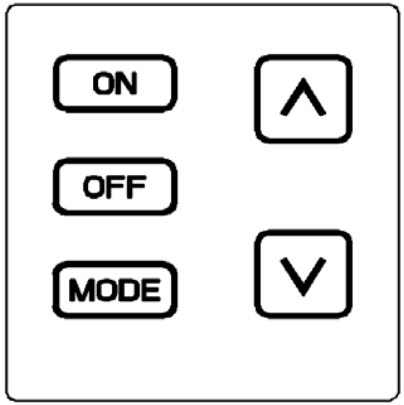
Key Settings
ON
Turns the heater ON. Manually operated solenoid ON.
OFF
Turns the heater OFF. Manually operated solenoid OFF.
MODE
Changes the heater from manual mode to thermostat mode
Sets the temperature in thermostat mode
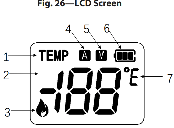
1. TEMP : Temperature indication.
2. DISPLAY : Indicates CURRENT room temperature.
3. FLAME : Indicates burner/valve in operation.
4.A : Thermostat function.
5.M : Manual function.
6.SET : Remote control battery display
7.°C to °F : Temperature in degrees F or C.
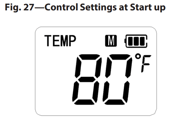
Control Settings at Start up (see Fig. 27):
After batteries are installed, press any button and the screen lights up and the room temperature is displayed in °F , the control is in manual mode and the battery level is displayed.
Setting °F/°C Scale
The factory setting for temperature is °F. To change this setting to °C Press the ON and OFF buttons on the remote/transmitter at the same time. Follow this same procedure to change from °C back to °F.
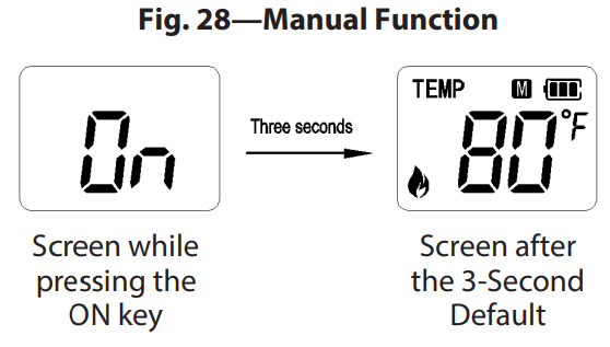
Manual Function (see Fig. 28):
To operate the remote system in the MANUAL MODE, do the following:
ON OPERATION
Press the “ON” button and the heater flame comes on. The display screen shows “ON” for three (3) seconds, the display shows the room temperature, and the flame icon
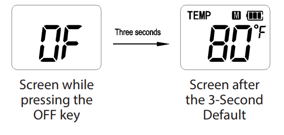
OFF OPERATION
Press the “OFF” button and the heater flame shuts off. The display screen shows “OFF" for three (3) seconds, display shows the room temperature, and the flame icon is off.
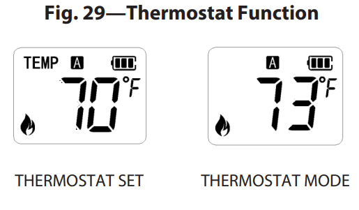
Thermostat Function (see Fig. 29):
When used as a vented decorative appliance, use of the thermostat function is prohibited—operate manually only. This remote control system can be thermostatically controlled when the control is in the A mode.
SETTING/CHANGING THE DESIRED ROOM TEMPERATURE To set theTHERMOSTAT MODE and the desired room temperature:
1. Press the MODE button to switch to Thermostat "A" function.
2. Press the “∧” and “∨” buttons choose the desired set temperature. Each time you press “∧” and “∨”, the temperature changes by 1 degree.
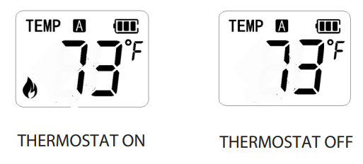
3. If the adjusted temperature is lower than the room temperature, the flame icon is off and the valve and burner flame shuts off.
4. If the adjusted temperature is higher than the room temperature, the flame icon is on and the valve and burner flame turns on.
Notes on Operation:
The heater is operated by the thermostat feature whenever the room temperature varies a certain number of degrees from the set temperature. This variation is known as “temperature differential” or “swing.” Based on how well your home is insulated from the cold, the normal operating cycle of the heater may be 2–4 times per hour. The “swing” comes preset from the factory at 2, which allows for a temperature variation of +/- 2°F (1°C) between the set temperature and the room temperature. This determines when the heater will begin operation. To activate the ON and OFF manual functions on the remote/transmitter, press either button on the face of the remote/transmitter. When “OFF” is pressed the valve and flame shuts off. When first used, a delay of three seconds may occur before the receiver responds to the remote/transmitter, which is normal.
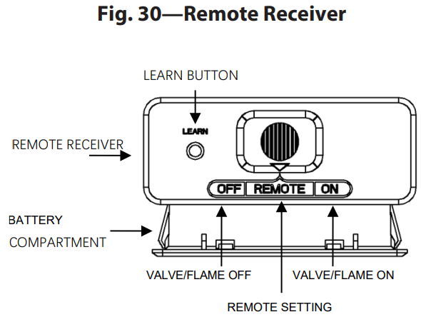
Remote Receiver:
The remote receiver (see Fig. 30) operates on four (4) 1.5V AA-size batteries. Always use alkaline batteries for longer battery life and maximum performance. Always use new/ fully charged batteries for proper operation of the remote receiver—the power consumption of a latching solenoid is much higher than standard remote control systems. Do not use rechargeable batteries.
NOTE: The remote receiver only responds to the remote/ transmitter when the 3-position slide button on the remote receiver is in the REMOTE position. The remote receiver contains the microprocessor, to which the remote/transmitter sends signals for operation
Functions:
• When the slide switch is in the REMOTE position, the system only operates if the receiver can receive commands from the remote/transmitter.
• When first used or after extended disuse, the “ON” button may have to be pressed for up to three (3) seconds before the valve is activated. On first use the system does not respond to the remote/transmitter, see LEARNING THE REMOTE/TRANSMITTER TO THE RECEIVER on page 26.
• The system can be manually turned on when the slide switch is in the ON position.
• The system is off when the slide switch is in the OFF position.
• If you’ll be away from the heater and/or your home for an extended period, we recommend keeping the slide switch in the OFF position.
• When the slide switch is in the OFF position, it also functions as a safety "lock out." This feature turns the system OFF and prevents the remote/transmitter from operating.
INSTALLATION INSTRUCTIONS
Installation:
You can mount the receiver on or near the fireplace hearth. ALWAYS PROTECT THE RECEIVER FROM EXTREME HEAT. Keep the receiver away from temperatures over 130º F inside the receiver case. Extreme temperatures also shorten battery life.
Hearth Mount:
You can place the receiver on the fireplace hearth or behind the fireplace control access panel. The receiver must be placed so that the temperature inside the receiver case does not exceed 130º F.
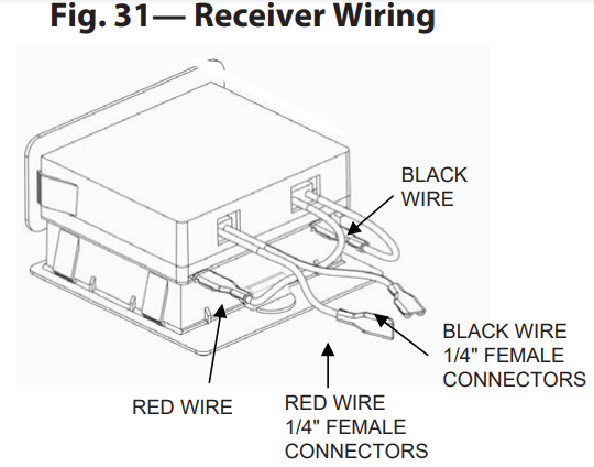
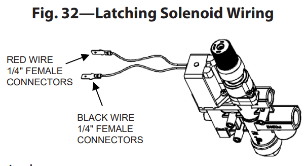
Wiring Instructions:
Ensure the receiver switch is in the OFF position. Use of 18-gauge stranded wires to make connections is recommended. Wires should not exceed 20 feet. Connect the receiver to a manual valve with a latching ON/OFF solenoid. Connect two 18-gauge stranded or solid wires from the remote receiver terminals to the latching solenoid (see Fig. 31 & 32).
NOTE: The operation of the controls depends on the way the wires are attached to the terminal. If the controls do not correspond to the operating buttons on the remote/transmitter, reverse the wire installation at the receiver or at the controls.
NOTE: Up to 6.3 VDC of power is provided at the receiver terminal
GENERAL INFORMATION
Communication/Safety/Remote-Transmitter
Built into the remote control’s software is a COMMUNICATION/SAFETY function. It provides an extra margin of safety when the remote/transmitter is out of the normal 20-foot operating range of the receiver. The COMMUNICATION/SAFETY feature operates the same in all operating modes. Every remote/transmitter has 16777216 unique security code. Upon first use, you must press the “LEARN” button on the receiver to verify the remote/transmitter security code. This process must be repeated if you replace the batteries or purchase a replacement remote/transmitter. To allow the remote/transmitter to accept the security code, the slide button on the receiver must be in the REMOTE position. If the slide switch is in the ON or OFF position, the receiver will not accept the security code. The “LEARN” button is located on the front face of the receiver, inside the small hole labeled “LEARN.” Press and release the black “LEARN” button inside the hole—a paper clip or small screwdriver works best, and press any button on the remote/ transmitter. When the “LEARN” button is released, the receiver emits a beeping pattern. The security code matching procedure uses a timing function. If the security code is not matched on the first attempt, wait 1–2 minutes and try again, which allows the timer to reset. Follow this procedure 2–3 times if necessary. Learning the Remote/Transmitter to the Receiver: In all operating modes and at all times, the remote/transmitter sends an RF signal every 15 minutes to the receiver. This indicates that the remote/transmitter is within the 20-foot normal operating range. If the receiver doesn’t receive a signal from the remote/transmitter every 15 minutes, the software in the receiver will begin a 2-hour countdown timing procedure. If the receiver does not receive a signal from the remote/ transmitter in this time, the receiver shuts off the heater. The receiver then emits a series of beeps for 10 seconds. After these 10 seconds, the receiver continues to emit a single beep every four (4) seconds until either the ON or MODE button on the remote/transmitter is pressed, which resets the receiver. The 4- second beeping goes on for as long as the receiver’s batteries last. To reset the receiver and operate the heater, press the “ON” or “MODE” button on the remote/transmitter. When the system is turned on, the COMMUNICATION/SAFETY beeping stops and the system returns to normal operation based on the MODE selected on the remote/transmitter. The COMMUNICATION/SAFETY feature restarts if the remote/transmitter is taken out of the normal operating range or the remote/ transmitter’s batteries fail or are removed.
Childproof Feature:
The remote control includes a CHILDPROOF “LOCK-OUT” feature, letting the user “lock-out” operation of the heater from the remote/transmitter.
To use the “LOCK-OUT” feature, do the following:
• To activate the “LOCK-OUT” feature, press and hold the “ON” button and the “MODE” button at the same time for five (5) seconds. The letters “CP” display in the TEMP frame on the LCD screen.
• To deactivate the “LOCK-OUT,” press and hold the “ON” button and the “MODE” button at the same time for five (5) seconds and the letters “CP” disappear from the LCD screen. The remote/transmitter then returns to normal operation.
• To verify remote/transmitter is in the CP lock-out mode, press any key and the LCD screen shows “CP.”
Learning the Remote/Transmitter to the Receiver:
Every remote/transmitter has 16777216 unique security code. Upon first use, you must press the “LEARN” button on the receiver to verify the remote/transmitter security code. This process must be repeated if you replace the batteries or purchase a replacement remote/transmitter. To allow the remote/transmitter to accept the security code, the slide button on the receiver must be in the REMOTE position. If the slide switch is in the ON or OFF position, the receiver will not accept the security code. The “LEARN” button is located on the front face of the receiver, inside the small hole labeled “LEARN.” Press and release the black “LEARN” button inside the hole—a paper clip or small screwdriver works best, and press any button on the remote/ transmitter. When the “LEARN” button is released, the receiver emits a beeping pattern. The security code matching procedure uses a timing function. If the security code is not matched on the first attempt, wait 1–2 minutes and try again, which allows the timer to reset. Follow this procedure 2–3 times if necessary.
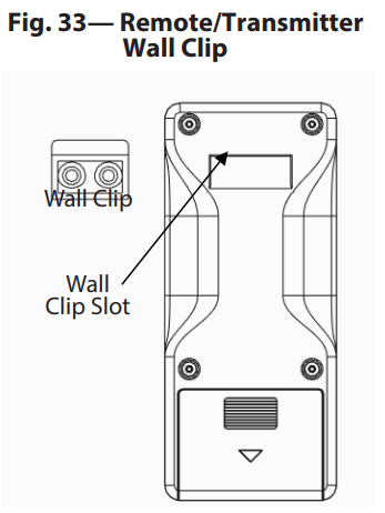
Remote/Transmitter Wall Clip (see Fig. 33):
You can hang the remote/transmitter on a wall using the provided clip. If installing on a solid wood wall, drill 1/8" pilot holes and use the provided screws. If installing on a plaster/ wallboard wall, first drill two 1/4" holes into the wall. Then, with a hammer, tap in the two plastic wall anchors so that they are flush with the wall. Then install the clip with the provided screws.
Battery Life:
Replace the batteries regularly. If the remote/transmitter no longer functions at a distance it previously did or the remote receiver does not function at all, check the batteries. The receiver batters should always provide a combined output voltage of at least 5.5 volts. The hand-held remote/transmitter should operate with as little as 2.5 volts of battery power.
TROUBLESHOOTING
Any problems with the log set may be a result of the log set malfunctioning, or it may be due to the remote system malfunctioning. First, review the manual to make sure all connections are properly made. Then check the remote system in the following ways:
• Ensure the batteries are correctly placed in the receiver. If a battery is inserted incorrectly, the remote system will not operate correctly.
• Check the battery in the remote/transmitter to ensure the contacts are touching the positive (+) and negative (-) ends of the battery. You can bend in the metal contacts for a tighter fit.
• Be sure the receiver and remote/transmitter are within a 20-25 foot range of one another.
• Do not allow receiver to exceed 130°F. Battery life is shortened when exposed to temperatures above 115°F.
• If the receiver is installed in such a way that it’s tightly enclosed in metal, the operating distance will be shortened.
• Do not use rechargeable batteries—they do not supply enough power.
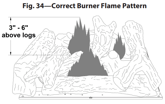
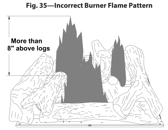
Figure 34 shows a correct burner flame pattern. Figure 35 shows an incorrect burner flame pattern. The incorrect burner flame pattern shows sporadic, irregular flame tipping. The flame should not be dark or have an orange/reddish tinge. NOTE: When using the heater the first time, the flame will be orange for approximately one hour. If the burner flame pattern is incorrect, as shown in Figure 35, do the following:
• Turn the heater off (see TO TURN OFF GAS TO THE HEATER, pages 24).
• See the TROUBLESHOOTING GUIDE, page 34.
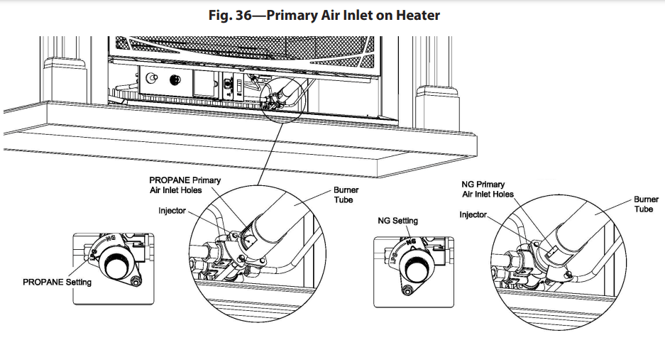
BURNER ORIFICE HOLDER AND PILOT AIR INLET HOLE
The primary air inlet holes allow the right amount of air to mix with the gas, which creates a clean burning flam . Keep these holes clear of lint, dirt, dust, pet hair, and other debris. Before every heating season, clean these holes—blocked air holes create soot. During operation, the heater should be cleaned at least every three (3) months. A qualified service person should inspect the heater yearly. Keep the burner tube and pilot assembly clean and free of dirt and other debris. Use compressed air of 30 PSI or less to clean these parts. If using compressed air in a can, follow the directions on the can exactly. You may damage the pilot assembly if the directions are not followed exactly
1. Shut off the heater, including the pilot. Allow the heater to cool for at least 30 minutes.
2. Inspect the burner, pilot, and primary air inlet holes on the orifice holder for dirt and debris (see Fig. 36).
3. Blow air through the ports/slots and holes in the burner.
4. Check the orifice holder again, which is located at the end of the burner tube. With a cloth or vacuum cleaner nozzle, remove any large particles of dust, dirt, or other debris.
5. Blow air into the primary air holes on the orifice holder.
6. Repeat steps 3 and 4. Clumps of dust/debris may have been pushed into the burner.
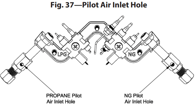
Clean the pilot assembly. A yellow tip on the pilot flame indicates dust and dirt in the pilot assembly. A small pilot air inlet hole is about 2" from where the pilot flame comes out of the pilot assembly (see Fig. 37). Ensure the heater is off, and lightly blow air through the air inlet hole. If you do not have compressed air, blowing through a drinking straw will also work.
Troubleshooting Guide
Problem
Possible Cause
Solution
There is no spark at the ODS/pilot when the ignitor button is pressed.
1. Ignitor electrode is positioned wrong.
2. Ignitor electrode is broken.
3. Ignitor electrode is not connected to ignitor cable.
4. Ignitor cable is pinched or wet.
5. Damaged ignitor cable.
6. Bad piezo ignitor.
1. Replace electrode.
2. Replace electrode.
3. Replace ignitor cable
4. Free the ignitor cable if it’s pinched by any metal or tubing. Keep ignitor cable dry.
5. Replace ignitor cable.
6. Replace piezo ignitor
When the ignitor button is pressed, there is a spark at the ODS/pilot but no ignition.
1. Gas supply is turned off o equipment shutoff valve is closed.
2. Control knob is not fully pressed in while pressing ignitor button.
3. Air in gas lines when installed.
4. ODS/pilot is clogged.
5. Gas regulator setting is incorrect.
6. Control knob not in PILOT position.
7. Depleted gas supply (propane)
1. Turn on the gas supply or the open equipment shutoff valve.
2. Fully press in the control knob while pressing the ignitor button.
3. Continue holding down the control knob. Repeat igniting operation until air is removed.
4. Clean ODS/pilot (see CARE AND MAINTENANCE, pages 32 & 33) or replace ODS/pilot assembly.
5. Replace gas regulator.
6. Turn control knob to PILOT position.
7. Contact local propane/LP gas company
ODS/pilot lights but flame goes out when the control knob is released.
1. Control knob is not fully pressed in.
2. Control knob is not pressed in long enough.
3. Equipment shutoff valve is not fully open.
4. Thermocouple connection is loose.
5. Thermocouple damaged.
6. Control valve damaged.
1. Press in control knob fully.
2. After ODS/pilot lights, keep control knob pressed in 30 seconds.
3. Fully open equipment shutoff valve.
4. Hand tighten until snug, and then tighten ¼ turn more.
5. Replace thermocouple.
6. Contact customer service.
Burner(s) does not light after ODS/pilot is lit.
1. Burner orifice is clogged.
2. Burner orifice diameter is too small.
3. Inlet gas pressure is too low.
1. Clean burner orifice (see CARE AND MAINTENANCE, pages 32 & 33) or contact customer service.
2. Contact customer service.
3. Contact your gas supplier.
Burner does not light after ODS/pilot is lit. (Heater is set up for natural gas.)
1. Inlet gas pressure is too high.
1. Contact your gas supplier.
There is delayed ignition of the burner(s).
1. Manifold pressure is too low.
2. Burner orifice is clogged.
1. Contact your gas supplier.
2. Clean burner (see CARE AND MAINTENANCE, pages 32 & 33) or contact customer service.
The burner is backfiring during combustion.
1. Burner orifice is clogged or damaged.
2. Burner is damaged.
3. Gas regulator is damaged.
1. Clean burner orifice (see CARE AND MAINTENANCE, pages 32 & 33, or contact customer service).
2. Contact dealer or customer service.
3. Replace gas regulator.
There is a high yellow flame during burner combustion.
1. There is not enough air.
2. Gas regulator is defective.
3. Inlet gas pressure is too low.
1. Check burner for dirt and debris. If found, clean burner (see CAREAND MAINTENANCE, page 32 & 33).
2. Replace gas regulator.
3. Contact your gas supplier.
A gas odor is present during combustion.
1. Foreign matter between control valve and burner.
2. Gas leak—see WARNING Statement at top of page 34.
1. Take apart gas tubing and remove foreign matter.
2. Locate and correct all leaks (see CHECKING GAS CONNECTIONS, page 21).
Heater produces a clicking/ticking noise just after burner is lit or shut off.
1. Metal is expanding while heating or contracting while cooling.
1. This is common with most heaters. If noise is excessive, contact a qualified service technician
White powder residue is forming within burner box or on adjacent walls or furniture.
1. When heated, the vapors from furniture polish, wax, carpet cleaners, etc. turn into white powder residue.
1. Turn heater off when using furniture polish, wax, carpet cleaner or similar products.
Heater produces unwanted odors
1. Heater is burning vapors from paint, hair spray, glues, etc. See IMPORTANT statement, page 34.
2. Gas leak—see WARNING Statement at the top of page 34.
3. The fuel supply is low.
1. Ventilate room. Stop using odor causing products while heater is running.
2. Locate and correct all leaks (see CHECKING GAS CONNECTIONS, page 21).
3. Refill supply tank (Propane /LP models).
Heater shuts off in use (ODS operates)
1. Not enough fresh air is available.
2. The line pressure is low.
3. ODS/pilot is partially clogged.
1. Open window and/or door for ventilation.
2. Contact local gas supplier.
3. Clean ODS/pilot (see CARE AND MAINTENANCE, page 32 & 33).
Gas odor exists even when control knob is in OFF position.
1. Gas leak—see WARNING Statement at top of page 34.
2. Control valve is defective.
1. Locate and correct all leaks (see CHECKING GAS CONNECTIONS, page 21).
2. Contact customer service.
Moisture/condensation is present on windows
1. Not enough combustion/ ventilation air is provided.
1. Refer to AIR FOR COMBUSTION AND VENTILATION requirements, pages 10–12.
There is slight smoke or odor during initial operation.
1. Residues from manufacturing process are present.
1. Problem will stop after a few hours of operation.
Heater produces a whistling noise when burner is lit
1. Turning control knob to high position when burner is cold.
2. There is air in the gas line.
3. Air passageways on heater are blocked.
4. Burner orifice are dirty or partially clogged.
1. Turn control knob to low position and let it warm up for a minute.
2. Operate burner until air is removed from line. Have gas line checked by local propane/LP gas company.


 to the “OFF” position (see Fig. 20).
  to the “PILOT” position (see Fig. 20). Depress the control knob.