1.0 INTRODUCTION
The GFK-160 Blower has been designed to circulate
room air through the fi replace to enhance heat output.
The GFK160 blower system operates on 120 VAC, 60 Hz
power. This is available through a receptacle in the factory
installed junction box. The junction box is located in the
controls compartment of the fi replace.
A variable speed control is provided with the blower fan kit
to provide quiet forced air fl ow at the desired speeds. A
temperature sensor switch, which automatically turns the
blower ON/OFF, is also provided with this kit.
NOTICE: The variable speed control and temperature
sensor swtich are not used with some remote control
systems.
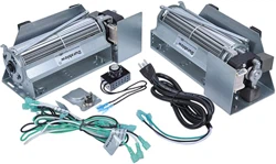
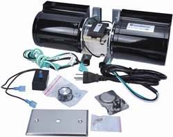
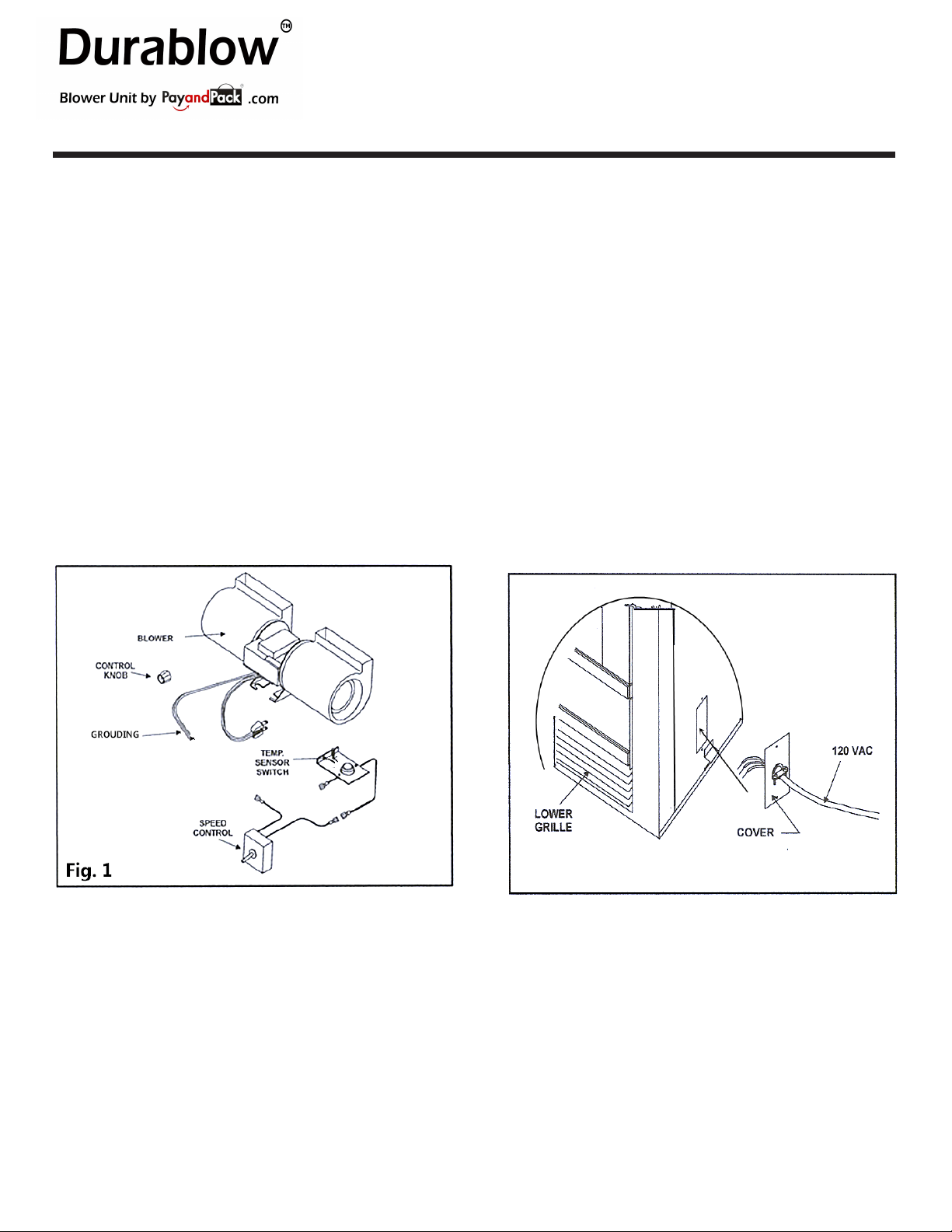
2.0 CHECK CONTENTS OF SHIPPING CARTON
Compare CONTENTS OF CARTON in Figure 1 with the
actual parts received. If any parts are missing or damaged,
contact your dealer before starting installation. Do not install
a damaged blower kit.
GFK-160 Blower Fan Kit
3.0 INSTALLATION PRECAUTIONS
The GFK-160 Blower Kit is tested and safe when installed
in accordance with this installation manual. It is your respon-
sibility to read all instructions before starting installation and
to follow these instructions carefully during installation to
assure maximum benefi t from, and safe operation of, the
blower.
This blower is carefully engineered and must be installed
only as specifi ed. If you modify it or any of its components,
you may cause a fi re hazard.
In addition, such action may void the coverage provided
by the owner's home insurance.
CAUTION: All wiring should be done by a qualifi ed electri-
cian and shall be in compliance with local codes and with
the National Electric Code ANSI/NFPA NO. 70-current (in
the United States), or with the current CSA C22.1 Canadian
Electric Code (in Canada).
CAUTION! DO NOT connect 110-120 VAC wiring to the
gas control valve of the fi replace.
4.0 INSTALLATION INSTRUCTIONS
4.1 INSTALLING ELECTRICAL SERVICE
TO THE JUNCTION BOX
WARNING: TURN ELECTRICAL POWER OFF AT THE
CIRCUIT BREAKER BEFORE BEGINNING THIS IN-
STALLATION.
1. Remove the electrical cover plate from the lower exterior
of the fi replace. Remove the knock-out from the plate
and attach the Romex clamp (screws to the outside).
(See Figure 2). NOTE: Some fi replace models have a
round hole through which the service wires are fed and
into which the Romex clamp is attached. These models
do not have a cover plate.
2. Feed the 110-120 VAC electrical service wires through
the Romex clamp and secure the wires to the clamp. Re-
attach the cover plate to the outside of the fi replace.
3. Access the controls compartment of the fi replace to
locate the Junction Box.
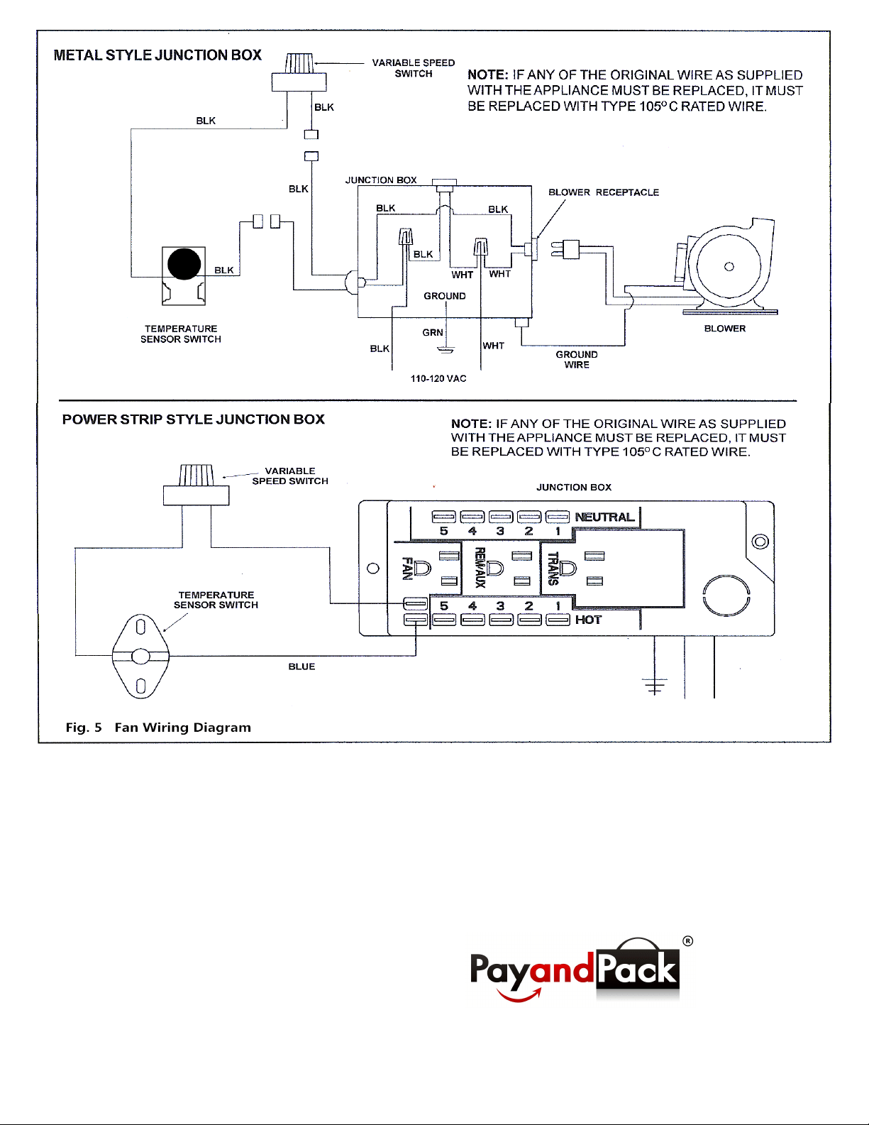
4. Using the wire nuts, attach the black wire to the black
service wire, the white wire to the white service wire, and
the service ground wire to the ground stud of the junction
box.
5. Attach the junction box to the side of the unit. Insert the
rear tab of the box into the rectangular slot in the outer
wrap of the fi rebox. Push the front end of the box tightly
against the side of the unit, and secure the box with a
sheet metal screw (note the hole in the front end tab).
INSTALLATION INSTRUCTIONS
PayandPack.com
(Also known as GFK160A, Fasco 7002-1241, A133, R7-RB168, HB-RB168, FAB-1600, FK-180, MFB160)
Page 1
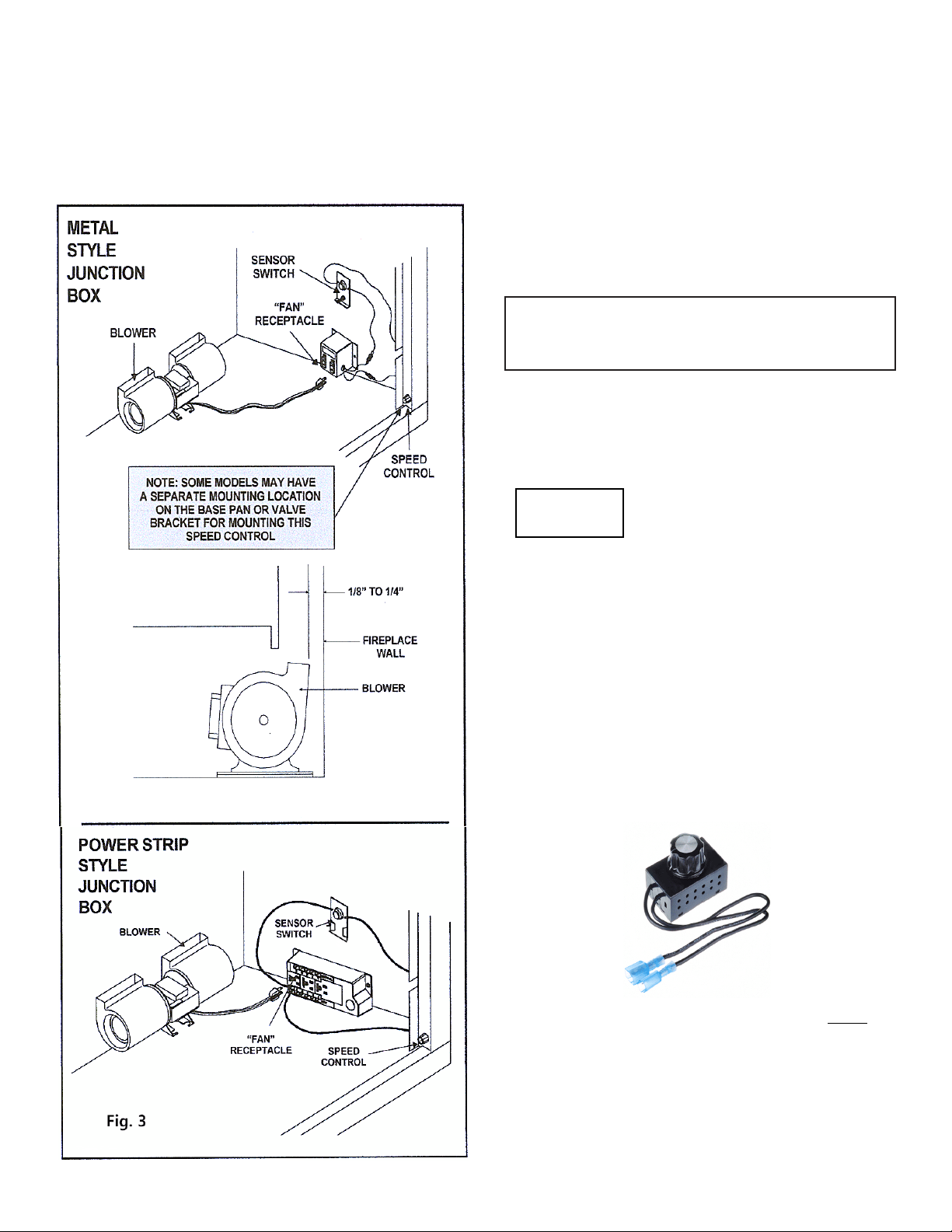
4.2 INSTALLING THE BLOWER
Position the blower all the way to the rear and cen-
ter in the fireplace. Pull the blower forward 1/8" to
1/4" from the back wall of the fireplace (Figure 3).
Or, you can have the two vertical brackets' "leg" stick
against to the rear wall of fireplace by Velcro strips.
4.3 INSTALLING THE SPEED CONTROL
AND SENSOR SWITCH
NOTE: Some models may have a separate mount-
ing location on the base pan or valve bracket for
mounting this speed control.
1. Remove the knob and locknut from the variable
speed control. Slide the control behind the
fireplace wall in the lower right front corner
with the stem sticking out of the pre-punched
hole. Attach the locknut tightly and reattach
the knob on the stem. Plug the blower into the
receptacle marked Rem/Aux or fan. This could
vary between models. This should be a
standard wall current or dedicated power.
2. Turn the 110-120 VAC series “ON” at the circuit
breaker and turn the speed control switch to
the “ON” position.
Unplug blower before changing
the location of the thermal
sensor. Possible electrical
shock if not unplugged.
3. The thermal sensor will turn blower on
approximately 10-20 minutes after the
fireplace is started and will continue to operate
up to 30 minutes after the fireplace has been
turned off. Times may vary depending on
sensor location.
Rubber feet may need to be removed from bracket to
install blower thorough front opening. If removed, put
the feet back on after the blower is through front
opening.
NOTE: THE SWITCH/BRACKET ASSEMBLY MUST
BE
INSTALLED SO THAT THE SENSOR SWITCH IS
TOWARDS THE TOP OF THE UNIT.
To turn off, turn dial
counterclockwise until
you hear it click.
To turn on, turn dial
clockwise from the off
position and the
blower will start on the
high setting. Continue
turning clockwise to
slow blower speed.
CAUTION
Page 2
5.0 RECOMMENDED OPERATING PROCEDURES
WHEN VARIABLE SPEED CONTROL AND
TEMPERATURE SWITCH ARE USED
Ignite the fi re in the fi replace with the variable speed control
switch in an "ON" position. The fan will automatically turn
on when the temperature sensor switch closes at approxi-
mately 120
O
F. Heated air should be delivered at the outlet
grille. The fan will continue to operate after the fi replace is
turned OFF until the sensor switch opens.
Various conditions (such as fi replace model, type of fi re-
place installation, outside air temperature vs. inside air
temperature) can contribute to the length of the time the
blower remains on after the fi replace is turned OFF. The
blower can be turned off manually with the speed control
switch.
WARNING! Risk of Injury! DO NOT contact blower
wheel (fan blades) during operation.
6.0 MAINTENANCE
Periodically check the fi replace grilles and remove any
dust, dirt or obstructions.
7.0 REPLACEMENT PARTS AND CUSTOMER
SERVICE
Replacement parts and service may be found in
our webstores or dealers.
PayandPack.com
Page 3
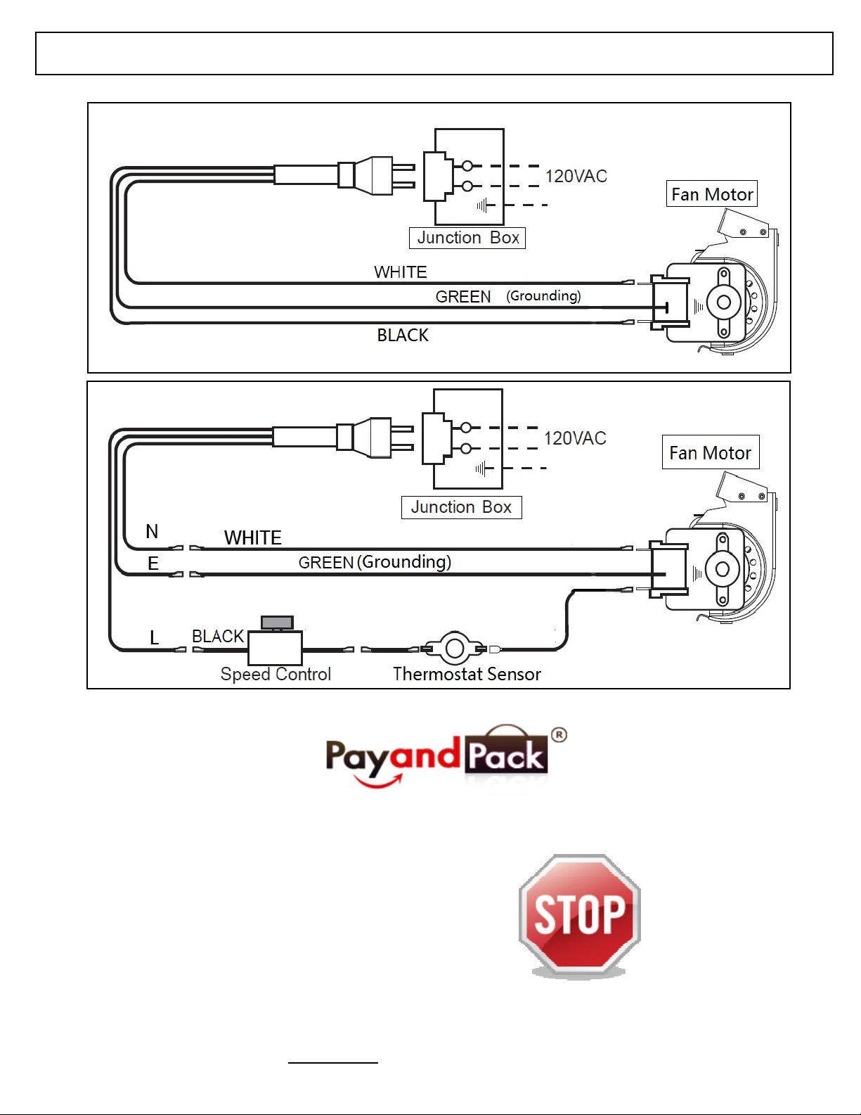
ATTENTION!
Before installation, please refer to your owners manual. The thermodisc is
set to turn on at approximately 120° F and will shut off at approximately 90° F.
NOTE: Blower will not start
until thermodisc is heated to approximately 120° F.
The thermodisc has been factory tested.
*The diagrams shown below are for normal blower reference only, please refer to original installation instructions.
PayandPack.com
1.
2.
Page 4