Intended to be installed by a qualified technician.
WARNING
Shock Risk / Explosion Risk
- DO NOT wire 110-120 VAC to gas control valve
- DO NOT wire 110-120 VAC to wall switch
• Incorrect wiring will damage millivolt values
• Incorrect wiring will override IPI safety lockout and
may cause explosion
NOTE: This appliance must be electronically wired and
grounded in accordance with local codes, or in the absence of
local codes, with National Electric Code ANSI/NFPA 70-
latest edition or the Canadian Electric Code CSA C22.1
CAUTION
Sharp Edges
• Wear protective gloves and safety glasses during
installation
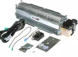
This is a factory replacement kit. The blowers are aftermarket
models with LIMITED INSTRUCTIONS!
NOT original parts.
INSTALLATION INSTRUCTIONS
PayandPack.com
Page 1
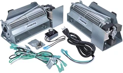
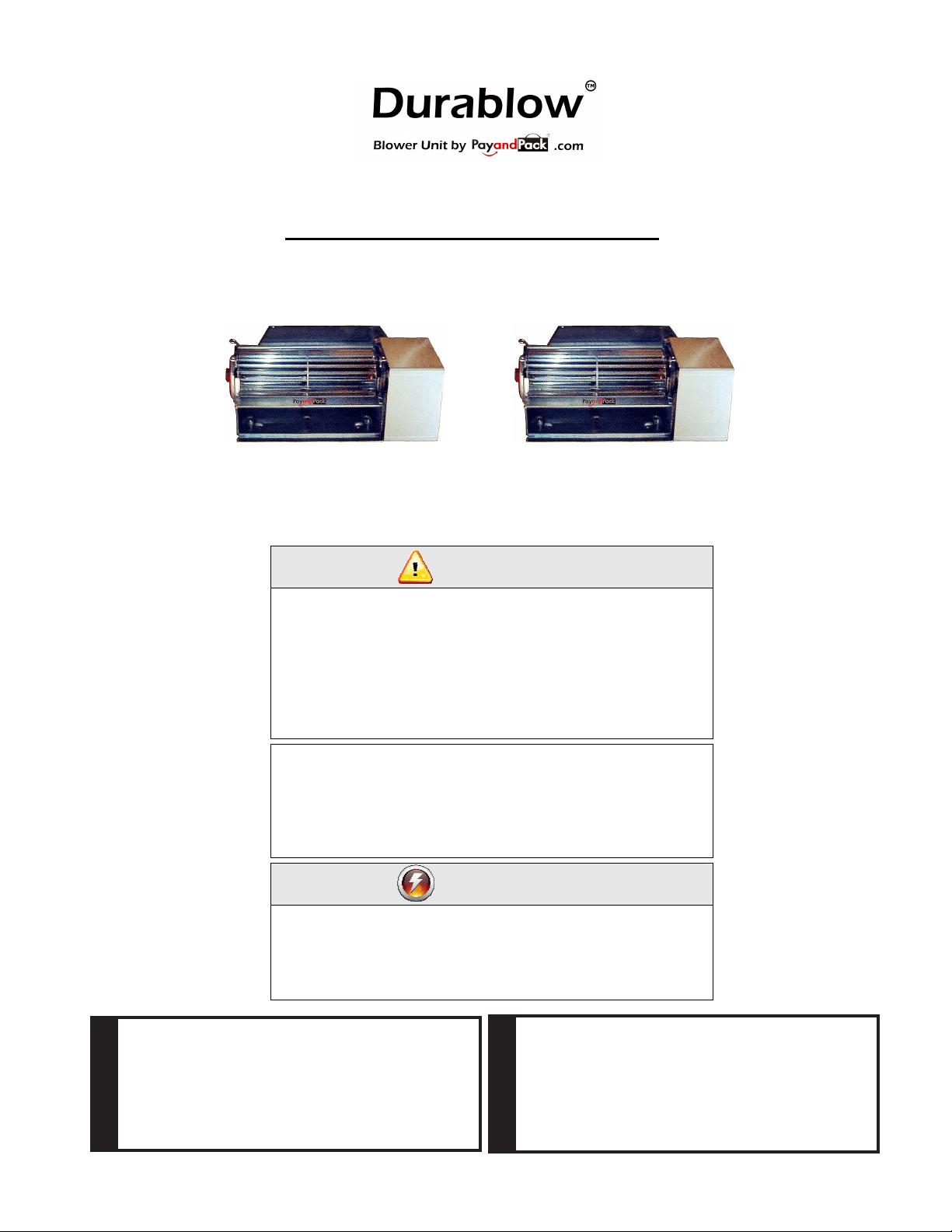
Model UZY5 Blower Kit (Two Blower Units)
NOTE: This blower kit can easily be installed when the fireplace has a pre-installed junction box.
You just have to plug them in.
Rating: 120 Volts, 60Hz, .63A.
CAUTION: SHOULD THIS BLOWER REQUIRE SERVICING, THE POWER SUPPLY MUST BE
DISCONNECTED.
Electrical Grounding Instructions: This
appliance is equipped with a three-prong
(grounding) plug for your protection against
shock hazard and should be plugged directly
into a properly grounded three-prong
receptacle.
warnIng
warnIng
Electrical connections should only be
performed by a qualified licensed electrician.
Main power supply must be turned off before
connecting the fan to the main electrical
power supply or performing service.
note
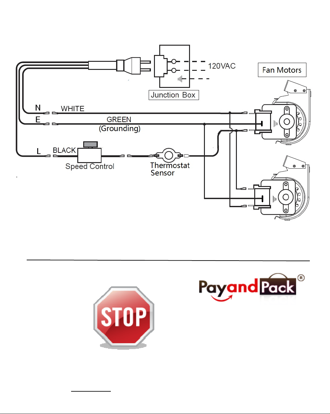
The black and white wires on the AC box
wiring harness are marked ‘Blower’, ‘Light’
and ‘Aux’. It is important to use the wires
marked ‘Blower’ or the control will not work
correctly.
Page 2
1. Open the bottom louver of the freplace.
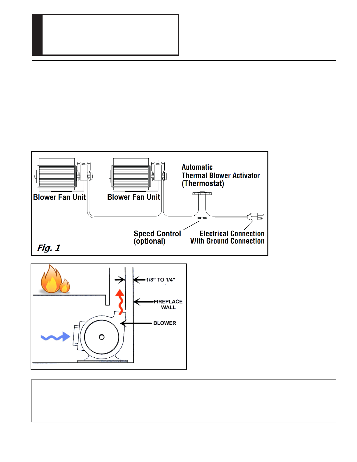
2. Place each blower kit into the freplace side opening,
leave a space of 1/8" - 1/4" from the back of the freplace. (See Fig. 2)
3. Install the automatic blower activator (Thermostat) on the side of the frebox.
(the thermostat has a magnetic mount, place it under the firebox)
4. Plug the blower kit into the junction box.
5. Ground both blowers to the back panel using the green screws. (see Fig. 1)
Fig. 2
These blowers require periodic maintenance.
Check the area in front of the blowers and wipe
or vacuum at least once a month during the burn
season.
MAINTENANCE:
The freplace must be electrically connected and grounded in accordance with local codes or in the absence of local
codes, with the current CSA C22.1 Canadian Electrical Code. For U.S.A. installations, follow local codes and the
National Electrical Code ANSI/NFPA No 70.
NOTE:
Installation instructions:
ATTENTION!
The thermodisc is set to turn on at approximately 120° F and
will shut off at approximately 90° F.
NOTE: Blower will not start
until thermodisc is heated to approximately 120° F.
The thermodisc has been factory tested.
PayandPack.com
BlotsdVautomatIcthermostatBlowerBlotsdVautomatIcthermostatBlowerBlotsdVautomatIcthermostatBlowerBlotsdVautomatIcthermostatBlowerBlotsdVautomatIcthermostatBlowerBlotsdVautomatIcthermostatBlowerBlotsdVautomatIcthermostatBlowerBlotsdVautomatIcthermostatBlowerBlotsdVautomatIcthermostatBlowerBlotsdVautomatIcthermostatBlowerBlotsdVautomatIcthermostatBlowerBlotsdVautomatIcthermostatBlowerBlotsdVautomatIcthermostatBlowerBlotsdVautomatIcthermostatBlowerBlotsdVautomatIcthermostatBlower
Page 3
*The diagrams shown below are for your reference only, please refer to original installation instructions.*The diagrams shown below are for your reference only, please refer to original installation instructions.*The diagrams shown below are for your reference only, please refer to original installation instructions.
*The diagrams shown below are for your reference only, please refer to original installation instructions.