
USER MANUALUSER MANUAL
AIRBLAZE
FIREPLACE BLOWER SYSTEM


3
WELCOME
Thank you for choosing AC Infinity. We are committed to product quality and friendly customer service.
If you have any questions or suggestions, please don’t hesitate to contact us. Visit www.acinfinity.com
and click contact for our contact information.
EMAIL
support@acinfinity.com
WEB
www.acinfinity.com
LOCATION
Los Angeles, CA
4
PRODUCT
AIRBLAZE T10
AIRBLAZE T12
AIRBLAZE T14
MODEL
AC-FBA10
AC-FBA12
AC-FBA14
UPC-A
00819137020863
00819137020870
00819137020887
MANUAL CODE 1810X1
SERIOUS INJURY OR DEATH. Please do not touch the blower’s impeller and
blades. Secure all nearby objects including wires and cables from coming
into contact with the blower’s impeller and blades. Use caution when
deciding where to install this blower.

5
MANUAL INDEX
Manual Index .................................................................................
Key Features .................................................................................
Product Contents ...........................................................................
Mounting ........................................................................................
Powering ........................................................................................
Programming .................................................................................
Other AC Infinity Products .............................................................
Warranty ........................................................................................
Page 5
Page 6
Page 7
Page 8
Page 11
Page 13
Page 21
Page 22
6
KEY FEATURES
SMART CONTROLLER
Digital controller adjusts
airflow in response to high and
low temperatures, as well as
humidity.
HEAVY DUTY BUILD
Cold-rolled steel construction
ensures the blower unit
can with stand an high
temperatures environment.
ANTI VIBRATION
The impeller is suspended in
mid-air with four silicone rubber
rivets to absorb vibrations and
reduce blower noise.
DUAL BALL BEARINGS
Fans contain long-life ball
bearings rated at 67,000
hours. Also enables fans to be
mounted in any direction.
PRECISE PROBE
The corded probe is
constructed of stainless steel
to ensure precise temperature
and humidity readings.
IP-32 PROTECTION
The blower unit is sealed to
Ingress Protection 32 standards
to be highly resistant to liquid
and dust.
7
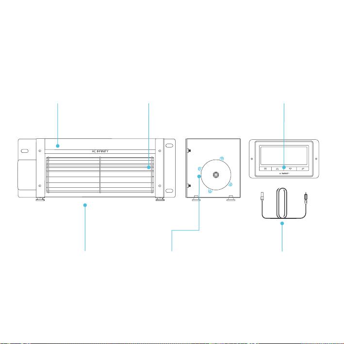
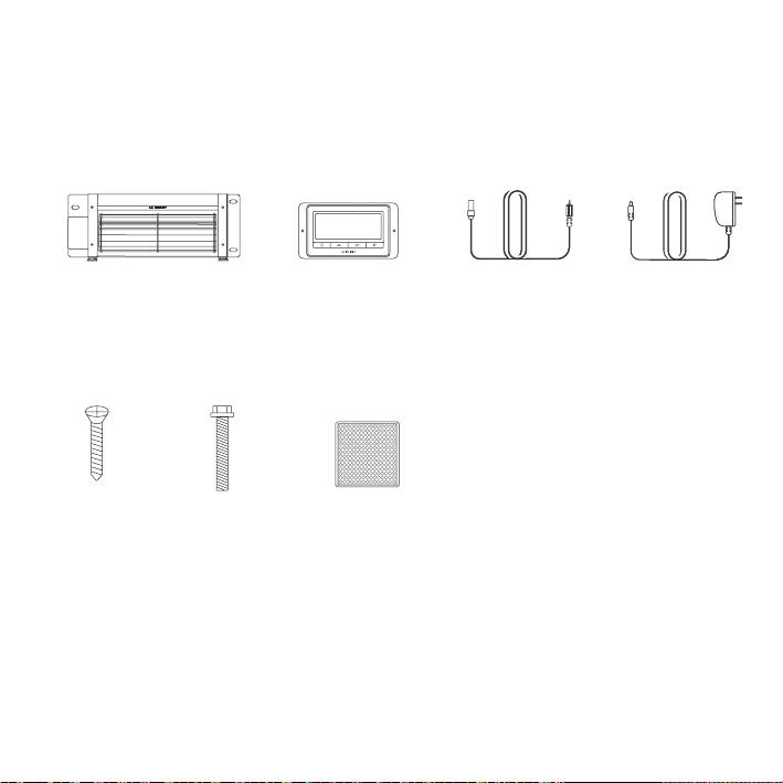
PRODUCT CONTENTS
AIRBLAZE FIREPLACE BLOWER SYSTEM (Included in all series)
SENSOR
PROBE
(x1)
WOOD
SCREW
(x3)
MOUNTING
SCREWS
(x3)
VELCRO
STRIPS
(x2) (x3) (x4)
POWER
ADAPTER
(x1)
UNIVERSAL
CONTROLLER
(x1)
BLOWER
UNIT
(x1)
8
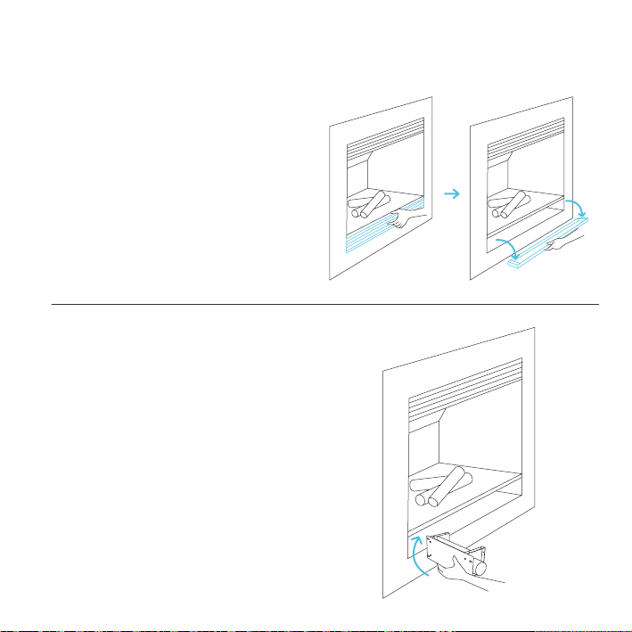
MOUNTING
STEP 1
WARNING: Turn off the gas and electrical
power before installing the kit!
While the fireplace is cool and off, remove the
lower half of the fireplace vent plate. Clean the
inside of the area of any dust or dirt.
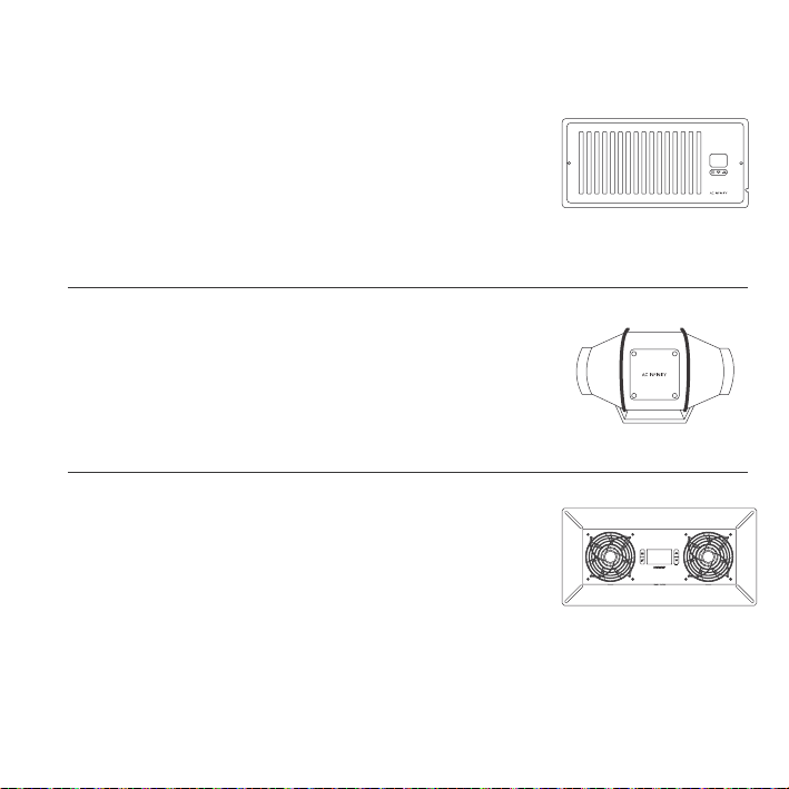
STEP 2
While very carefully placing the blower towards
the rear, be sure the opening of the fan in which
the air blows out is facing up and the rubber
feet are facing the floor. Avoid any gas lines or
electrical wires that are already in place.
9
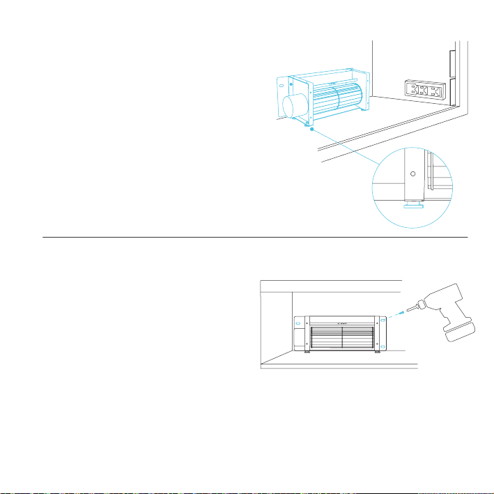
MOUNTING
STEP 4
Be sure that the area you are mounting has no
gas lines or electrical wires in the way of the
drilling area. Use a power drill to mount the fan
in place with the included screws to reduce any
unwanted vibrations.
STEP 3
Be sure the metal plate is placed towards the
wall of the vent and the rubber feet are placed
against the floor with the fan blades facing
forward as pictured in the illustration.
10
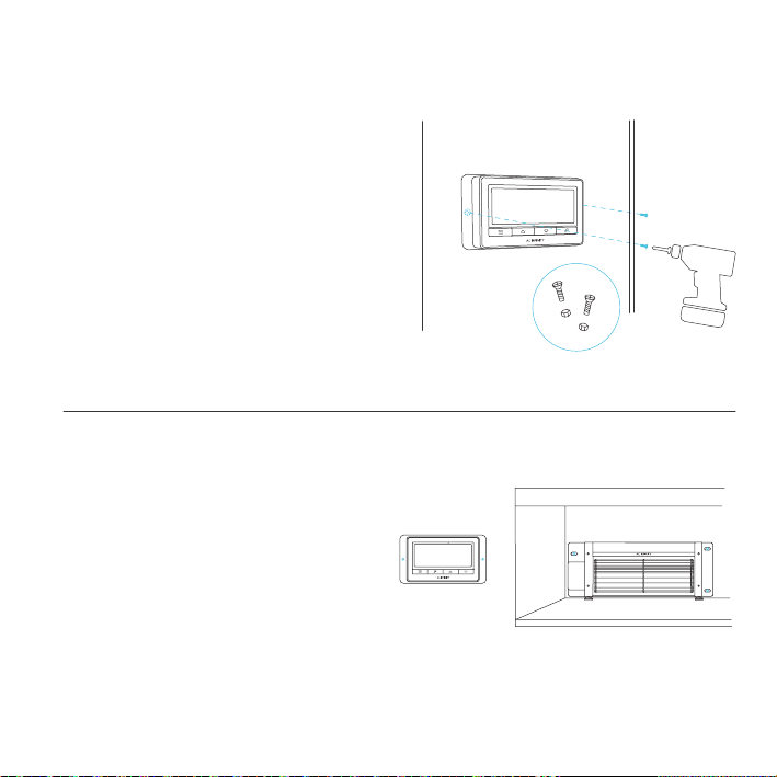
MOUNTING
STEP 5
To mount the controller, position it on the
outside of the vent away from the fireplace
and use the included screw sets. Use a drill to
screw the controller into place.
STEP 6
Once the fan and Universal Controller are
securely mounted with in a safe distance, you
are now able to continue to powering.
11
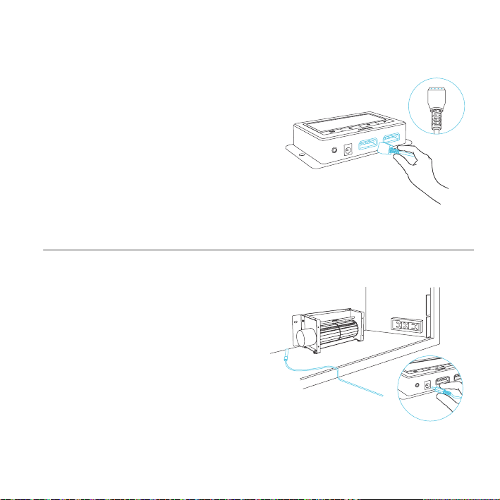
STEP 1
The blower unit comes corded with
a 4-pin molex connector. Locate the connector
and plug it into the bottom of the controller.
Please make sure the this cord is secured
away from contacting the blower’s spinning
impeller and blades.
POWERING
STEP 2
Plug in the thermal probe directly under the
controller, the probe has to be placed with in
the same area as the blower underneath the
fireplace. The probe should be able to detect
heat once the fire place is on to start the blower.
Please make sure the this cord is secured away
from contacting the blower’s spinning impeller
and blades.

12
POWERING
STEP 4
Follow the instructions starting on page 13 to
program the controller. When the sensor probe
detects a temperature or humidity that exceeds
your settings, the blower will starting moving
air. This accelerates air being moved from the
bottom of the fireplace vents, through the fire
place, and exhausting out the top. The heated
air that the fireplace created will circulate back
into the room at a faster face and warm up a
larger area.
STEP 3
To power the device, plug the adapter pin into
the Universal controller, and the prong end into
the outlet inside the fire place or outside the
fireplace if there are no outlets.
13
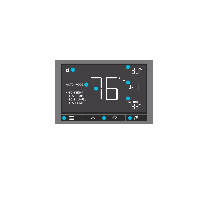
PROGRAMMING
1. MODE BUTTON
This button cycles through
each of the controller's
modes: ON, OFF, TIMER,
AUTO (4 triggers), and
ALARM (4 settings).
4. PROBE TEMP.
Displays the current tempera-
ture that the corded sensor
probe is measuring. Shows
“- -” if no probe is plugged in.
8. FAN SPEED
Displays the current speed
the fan is running at, or what
speed it should be running at
if no fans are plugged in.
6. ALERT ICONS
This area displays the alerts
and statuses from the
controller including alarms
and screen lock.
9. SETTING
Displays the value you
have set for the current
mode. Press the up or
down button to change.
7. PROBE HUMIDITY
Displays the current humidity
that the corded sensor probe
is measuring. Shows “- -” if
no probe is plugged in.
5. CONTROLLER MODE
This area displays the mode
that the controller is currently
in. Press the Mode Button to
cycle through the modes.
3. LEAF BUTTON
This turns the display off
while programs run in the
background. Hold for two
seconds to lock or unlock
the display.
2. UP / DOWN BUTTON
The up and down buttons
adjusts the settings of the
mode that you are in. Up
button increases and
down button decreases.
1 2 3
4
7
8
9
6
5
14
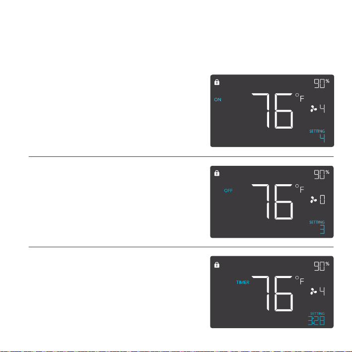
ON MODE
In this mode, the fans will run continuously
regardless of temperature or humidity. The
speed set in this mode will be the max speed
the fans can reach in AUTO Mode.
OFF MODE
In this mode, the fans will not run regardless
of temperature or humidity. While in this mode,
pressing the up or down button will change the
display’s brightness. Holding up or down button
will change the display’s units F or C.
PROGRAMMING
MODE SETTING
Press the Mode button to cycle through the controller’s available programming modes and settings:
ON Mode, OFF Mode, TIMER Mode, AUTO Mode (4 triggers), ALARM Settings (4 settings).
TIMER MODE
In this mode, press the up or down button to set
a time for the timer. The fans will run at the speed
set in ON Mode until the timer’s clock runs out,
in which the fans will stop running. The clock will
begin counting down if no buttons are pressed
for 3 seconds. Leaving the timer mode while the
countdown is running will pause the clock until you
return to this mode.
15
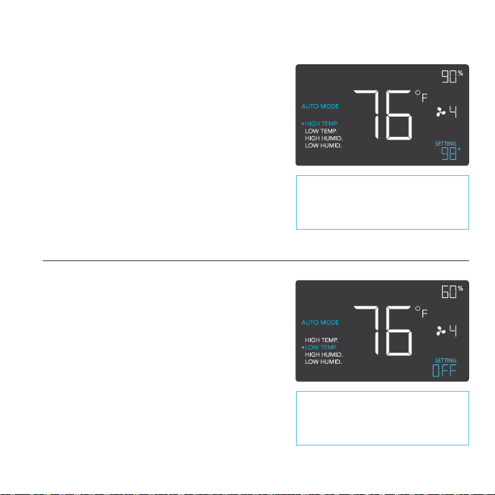
PROGRAMMING
AUTO MODE: HIGH TEMP.
In this mode, press the up or down button to set a
high temperature trigger. The fans will activate if the
probe’s measured temperature exceeds the tem-
perature you have set in this mode. The activated
fans will slowly increase in speed until it reaches
the speed set in ON Mode. Whenever the measured
temperature falls below your set temperature, the
fans will slowly decrease in speed until the fans
stop. You may also hold the up and down button
simultaneously to turn off this trigger, in which the
digits under settings will show OFF.
AUTO MODE: LOW TEMP.
In this mode, press the up or down button to set
a low temperature trigger. The fans will activate
if the probe’s measured temperature falls below
the temperature you have set in this mode. The
activated fans will slowly increase in speed until
it reaches the speed set in ON Mode. Whenever
the measured temperature rises above your set
temperature, the fans will slowly decrease in speed
until the fans stop. You may also hold the up and
down button simultaneously to turn off this trigger, in
which the digits under settings will show OFF.
Note that this trigger can activate as
long as you are in AUTO Mode, even
if you are viewing a dierent trigger
within AUTO Mode.
Note that this trigger can activate as
long as you are in AUTO Mode, even
if you are viewing a dierent trigger
within AUTO Mode.
16
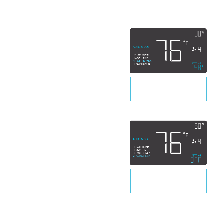
PROGRAMMING
AUTO MODE: HIGH HUMID.
In this mode, press the up or down button to set a
high humidity trigger. The fans will activate if the
probe’s measured humidity exceeds the humidity
you have set in this mode. The activated fans will
slowly increase in speed until it reaches the speed
set in ON Mode. Whenever the measured humidity
falls below your set humidity, the fans will slowly
decrease in speed until the fans stop. You may also
hold the up and down button simultaneously to turn
off this trigger, in which the digits under settings will
show OFF.
AUTO MODE: LOW HUMID.
In this mode, press the up or down button to set
a low humidity trigger. The fans will activate if the
probe’s measured humidity falls below the humidity
you have set in this mode. The activated fans
will slowly increase in speed until it reaches the
speed set in ON Mode. Whenever the measured
humidity rises above your set temperature, the
fans will slowly decrease in speed until the fans
stop. You may also hold the up and down button
simultaneously to turn off this trigger, in which the
digits under settings will show OFF.
Note that this trigger can activate as
long as you are in AUTO Mode, even
if you are viewing a dierent trigger
within AUTO Mode.
Note that this trigger can activate as
long as you are in AUTO Mode, even
if you are viewing a dierent trigger
within AUTO Mode.
17
PROGRAMMING
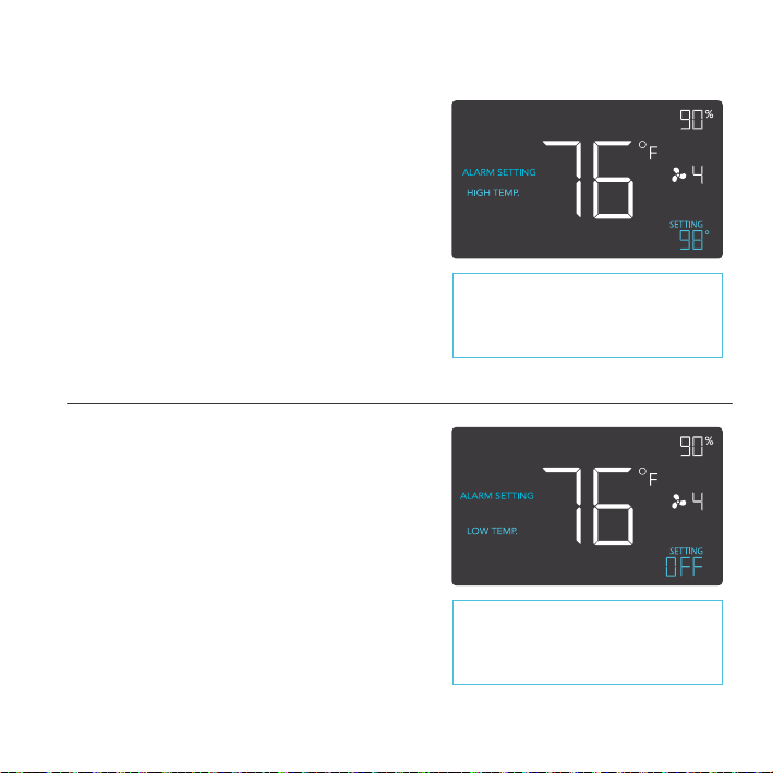
ALARM SETTING: HIGH TEMP.
In this settings mode, press the up and down
button to set a high temperature alarm. The
alarm will activate if the probe’s measured
temperature exceeds the temperature you have
set in this mode. When the alarm triggers, the
fan will start spinning gradually to max speed
regardless of your other settings. You may also
hold the up and down button simultaneously
to turn off this alarm, in which the digits under
settings will show OFF.
Note that alarm triggers can only
activate in AUTO, ON, or TIMER
Mode. Please leave ALARM
SETTING to arm the controller.
ALARM SETTING: LOW TEMP.
In this settings mode, press the up and down
button to set a low temperature alarm. The
alarm will activate if the probe’s measured tem-
perature falls below the temperature you have
set in this mode. When the alarm triggers, the
fan will start spinning gradually to max speed
regardless of your other settings. You may also
hold the up and down button simultaneously
to turn off this alarm, in which the digits under
settings will show OFF.
Note that alarm triggers can only
activate in AUTO, ON, or TIMER
Mode. Please leave ALARM
SETTING to arm the controller.
18
PROGRAMMING
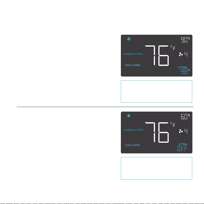
ALARM SETTING: HIGH HUMID.
In this settings mode, press the up and down
button to set a high humidity alarm. The alarm
will activate if the probe’s measured humidity
exceeds the humidity you have set in this
mode. When the alarm triggers, the fan will
start spinning gradually to max speed regard-
less of your other settings. You may also hold
the up and down button simultaneously to turn
off this alarm, in which the digits under settings
will show OFF.
ALARM SETTING: LOW HUMID.
In this settings mode, press the up and down
button to set a low temperature alarm. The
alarm will activate if the probe’s measured tem-
perature falls below the temperature you have
set in this mode. When the alarm triggers, the
fan will start spinning gradually to max speed
regardless of your other settings. You may also
hold the up and down button simultaneously
to turn off this alarm, in which the digits under
settings will show OFF.
Note that alarm triggers can only
activate in AUTO, ON, or TIMER
Mode. Please leave ALARM
SETTING to arm the controller.
Note that alarm triggers can only
activate in AUTO, ON, or TIMER
Mode. Please leave ALARM
SETTING to arm the controller.

19
PROGRAMMING
DISPLAY BRIGHTNESS
To adjust the brightness of the display, please set the controller to OFF Mode, then press the up or
down button to increase or decrease the brightness level. Three brightness settings are available.
FAHRENHEIT OR CELSIUS
To change to displayed units between Fahrenheit and Celsius, please set the controller to OFF
Mode, then hold the up button for Fahrenheit (°F) or hold the down button for Celsius (°C).
ECO-MODE
The controller can be put into ECO display in which the screen will be turned off but all programs,
settings, and alarms will be running in the background. This can be done by pressing the LEAF
button. You may also do this while the controller is locked. To exit ECO display, simply press any
buttons.
TEMPERATURE CALIBRATION
To adjust the temperature that the probe sensor is measuring, please press the MODE and UP
button simultaneously. This can be done while the controller is any mode or setting. The calibration
cycle ranges from -8°F to 8°F (or -4°C to 4°C) and will be applied to the probe sensor’s measure-
ments.
HUMIDITY CALIBRATION
To adjust the humidity that the probe sensor is measuring, please press the MODE and DOWN
button simultaneously. This can be done while the controller is any mode or setting. The calibration
cycle ranges from -8% to 8% and will be applied to the probe sensor’s measurements.
CONTROLLER LOCK
To lock the controller to prevent settings to be changed accidentally, hold the LEAF button for two
or more seconds. While the display is locked, you will not be able to switch modes or changes any
settings. You will only be able to put the controller in ECO display by pressing the LEAF button.
Holding the LEAF button for two or more seconds will unlock the controller.
20
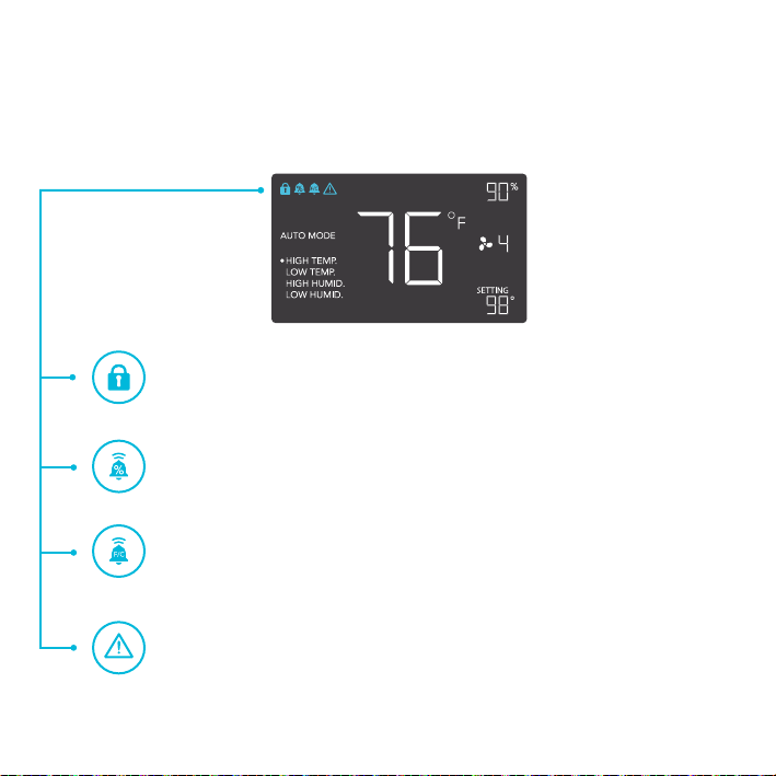
PROGRAMMING
FAN FAILURE ALERT
This icon will flash when the controller sense that the fans have failed. Please note
that not all controllers have this feature. Please see the warranty page for product
replacement information.
TEMPERATURE ALARM ALERT
This icon will flash when the high or low temperature alarm that you have set has
been triggered.
HUMIDITY ALARM ALERT
This icon will flash when the high or low humidity alarm that you have set has been
triggered.
DISPLAY LOCK ALERT
This icon is visible when the controller has been locked. The icon will flash to alert
you that the controller is locked if you try to change the mode or settings.
ALERT ICONS
On the top left of the display is the alert icon section. Icons may flash when the controller wishes to
alert you that a particular function or alarm is being triggered.
21
AC INFINITY PRODUCTS
Register Booster Fans
The AIRTAP series is a line of register booster fans designed to
quietly increase airflow coming from your central heat and air
conditioning systems, increasing comfort for your home. Features a
thermal controller with intelligent programming that will automatically
adjust airflow strength in response to heating and cooling
temperatures you have set.
Duct Fans
The CLOUDLINE series is a line of duct fans designed to quietly
ventilate AV rooms and closets, as well as various DIY air circulation
and exhaust projects. Features a thermal controller with intelligent
programming that will automatically adjust duct fan speeds in re-
sponse to changing temperatures.
Crawlspace Fans
The AIRTITAN is a line of weather-proof fans designed to
provide ventilation, odor, and moisture control for crawl spaces
and basements. It features a digital controller with intelligent
programming that will adjust airflow strength in response to high
and low temperatures, as well as humidity.
Discover the latest innovations in cooling and ventilation at acinfinity.com

22
WARRANTY
If you are not 100% satisfied with this product, we will be happy
to replace it or issue you a full refund. Please contact us!
This warranty program is our commitment to you, the original purchaser, that each product sold
by AC Infinity will be free from defects in manufacturing for a period of two years from the date
of purchase. If a product is found to have a defect in material or workmanship, we will take the
appropriate actions defined in this warranty to resolve any issues.
The warranty program applies to any order, purchase, receipt, or use of any products from AC
Infinity. The program covers products that have become defective, malfunctioned, or expressively if
the product becomes unusable. The warranty program goes into effect on the date of purchase. The
program will expire two years from the date of purchase. If your product becomes defective during
that period, AC Infinity will replace your product with a new one or issue you a full refund.
The warranty program does not cover abuse or misuse. This includes physical damage,
submersion of the product in water, incorrect Installation such as wrong voltage input, and misuse
for any reason other than intended purposes. AC Infinity is not responsible for consequential loss or
incidental damages of any nature caused by the product. We will not warrant damage from normal
wear such as scratches and dings.


COPYRIGHT © 2018 AC INFINITY INC. ALL RIGHTS RESERVED
No part of the materials including graphics or logos available in this booklet may be copied,
photocopied, reproduced, translated or reduced to any electronic medium or machine
readable form, in whole or in part, without specific permission from AC Infinity Inc.


www.acinnity.com


