Loading ...
Loading ...
Loading ...
7
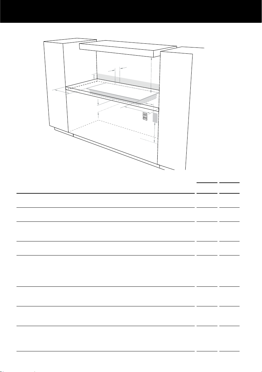
INSTALLATION INSTRUCTIONS
A
E
C
D
F
B
G
H
Drawings for illustration purposes only
CLEARANCE DIMENSIONS
CG604C
CG905C
MM MM
A
Minimum clearance from left edge of cutout to:
nearest combustible surface
140 140
B
Minimum clearance from right edge of cutout to:
nearest combustible surface
140 140
C
Minimum clearance from rear edge of cutout to:
nearest combustible surface
nearest non-combustible surface
112
20
112
30
D
Minimum height of non-combustible material when used on adjacent
walls (See section ‘Standards requirements’ following)
150 150
E
Minimum clearance from pan supports to:
rangehood
any other overhead exhaust fan
downward-facing combustible surface (overhead cabinetry)
downward-facing tiled or fire-resistant surface
650
800
650
500
650
800
650
500
F
Minimum clearance below top of benchtop to:
nearest combustible surface
F&P oven or nearest non-combustible surface
60
60
60
60
G
Ensure there is an earthed power outlet within 900mm of the rear right-
hand corner of the cooktop. The outlet should be accessible with the
cooktop installed.
H
If connecting the cooktop to the gas supply with a flexible hose, the
connector on the wall should be between 800-850mm above the floor
and to a distance of at least 250mm outside the width of the cooktop.
The connector should be accessible with the cooktop installed.
Clearances
Loading ...
Loading ...
Loading ...