Loading ...
Loading ...
Loading ...
- 9 -
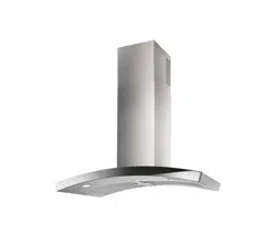
ROOF CAP
8-INCH
ROUND DUCT
DECORATIVE
FLUE
HOOD
WALL
CAP
8-INCH
ROUND
ELBOW
24” TO 30”
ABOVE
COOKING
SURFACE
(see “INSTALL
MOUNTING
BRACKETS”
section for
mounting
restrictions)
4¼”
DISTANCE
FROM
CENTERLINE
OF DUCT TO
DRYWALL
INSTALL THE DUCTWORK
DUCTED HOODS ONLY
CAUTION: To reduce the risk of fire, use
only metal ductwork.
1. Decide where the ductwork will run be-
tween the hood and the outside. Fig. 3.
2. A straight, short duct run will allow the
hood to perform most efficiently.
3. Long duct runs, elbows, and transitions
will reduce the performance of the hood.
Use as few of them as possible. Larger
ducting may be required for best perfor-
mance with longer duct runs.
4. Install a roof or wall cap. Connect round
metal ductwork to cap and work back
towards hood location. Use duct tape to
seal the joints between ductwork sections.
INSTALL ELECTRICAL
DUCTED and NON-DUCTED HOODS
WARNING : Electrical wiring must
be done by a qualified person(s) in ac-
cordance with all applicable codes and
standards. This range hood must be prop-
erly grounded. Turn off electrical power at
service entrance before wiring.
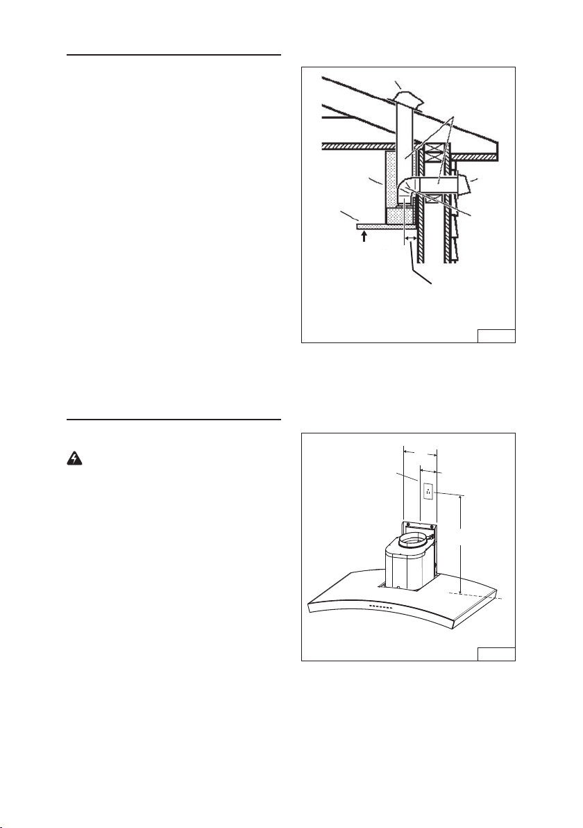
1. Plan where the hood will be located
above the cook top. Refer to the “INSTALL
MOUNTING BRACKET” section for hood
mounting height options.
2. Install a standard 2” x 4” wall outlet box
and 3-blade 125 volt, 15 Amp grounded
receptacle. Fig. 4.
3. Mount the center of the wall outlet 18½”
to 19½” above the bottom of the hood.
4. Locate the box and the receptacle within
boundary shown and off center of the
ductwork (to allow for power cord plug
and flue clearance).
FIG. 4
18½” to 19½”
4”
8”
CENTERLINE
OF HOOD
FIG. 3
Loading ...
Loading ...
Loading ...