
WC35 Series
ENGLISH.....................................2
FRANÇAIS.................................24
ESPAÑOL.................................. 47
In USA - BEST Hartford, Wisconsin
In CANADA - BEST Drummondville, QC, Canada
REGISTER YOUR PRODUCT ONLINE AT : www.BestRangeHoods.com/register
For additional Information visit www.BestRangeHoods.com
- 2 -
READ AND SAVE THESE INSTRUCTIONS
WARNING
TO REDUCE THE RISK OF FIRE, ELECTRIC SHOCK, OR INJURY TO PERSONS, OBSERVE
THE FOLLOWING:
1. Use this unit only in the manner intended by the manufacturer. If you have questions, contact
the manufacturer at the address or telephone number listed in the warranty.
2. Before servicing or cleaning unit, switch power off at service panel and lock service panel to
prevent power from being switched on accidentally. When the service disconnecting means can-
not be locked, securely fasten a prominent warning device, such as a tag, to the service panel.
3. Installation work and electrical wiring must be done by a qualified person(s) in accordance with
all applicable codes and standards, including fire-rated construction codes and standards.
4. Sufficient air is needed for proper combustion and exhausting of gases through the flue (chimney)
of fuel burning equipment to prevent backdrafting. Follow the heating equipment manufacturer’s
guidelines and safety standards such as those published by the National Fire Protection Associa-
tion (NFPA), and the American Society for Heating, Refrigeration and Air Conditioning Engineers
(ASHRAE), and the local code authorities.
5. When cutting or drilling into wall or ceiling, do not damage electrical wiring and other hidden
utilities.
6. Ducted fans must always be vented to the outdoors.
7. Do not use this unit with any separate solid-state speed control device.
8. To reduce the risk of fire, use only metal ductwork.
GROUNDING INSTRUCTIONS
This appliance must be grounded. In the event of an electrical short circuit, grounding reduces the
risk of electrical shock by providing an escape wire for the electric current. This appliance is equipped
with a cord having a grounding wire with a grounding plug. The plug must be plugged into an outlet
that is properly installed and grounded.
WARNING - Improper grounding can result in a risk of electric shock.
Consult a qualified electrician if the grounding instructions are not completely understood, or if doubt
exists as to whether the appliance is properly grounded.
Do not use an extension cord. If the power supply cord is too short, have a qualified electrician install
an outlet near the appliance.
!
INTENDED FOR DOMESTIC COOKING ONLY
!
- 3 -
!
CAUTION
1. For indoor use only.
2. To reduce risk of fire and to properly exhaust air, be sure to duct air outside. Do not vent exhaust
air into spaces within walls or ceilings or into attics, crawl spaces, or garages.
3. Take care when using cleaning agents or detergents.
4. Avoid using food products that produce flames under the Range Hood.
5. For general ventilating use only. Do not use to exhaust hazardous or explosive materials and
vapors.
6. To avoid motor bearing damage and noisy and/or unbalanced impellers, keep drywall spray,
construction dust, etc. off power unit.
7. Your hood motor has a thermal overload which will automatically shut off the motor if it becomes
overheated. The motor will restart when it cools down. If the motor continues to shut off and
restart, have the hood serviced.
8. For best capture of cooking impurities, the bottom of the hood should be a minimum of 24”
and a maximum of 30” above the cooking surface. See “Install Mounting Bracket” section for
mounting restrictions.
9. Two installers are recommended because of the large size and weight of this hood.
10. This product is equipped with a thermostat which may start blower automatically. To reduce
the risk of injury and to prevent power from being switched on accidentally, switch power off at
service panel and lock or tag service panel.
11. Please read specification label on product for further information and requirements.
12. EXTERNAL BLOWER MODELS ONLY: To reduce the risk of fire and electric shock, install this
range hood only with Best Exterior Blower Models EB6, EB9, EB12 or EB15 or Best In-Line
Blower Models ILB3, ILB6, ILB9 or ILB11. Other blower cannot be substituted. Blowers sold
separately.
WARNING
TO REDUCE THE RISK OF A RANGE TOP GREASE FIRE:
A. Never leave surface units unattended at high settings. Boilovers cause smoking and greasy
spillovers that may ignite. Heat oils slowly on low or medium settings.
B. Always turn hood ON when cooking at high heat or when flambeing food (i.e. Crepes Suzette,
Cherries Jubilee, Peppercorn Beef Flambé).
C. Clean ventilating fans frequently. Grease should not be allowed to accumulate on fan or filter.
D. Use proper pan size. Always use cookware appropriate for the size of the surface element.
TO REDUCE THE RISK OF INJURY TO PERSONS IN THE EVENT OF A RANGE TOP GREASE
FIRE, OBSERVE THE FOLLOWING:*
1. SMOTHER FLAMES with a close-fitting lid, cookie sheet, or metal tray, then turn off the burner.
BE CAREFUL TO PREVENT BURNS. If the flames do not go out immediately, EVACUATE AND
CALL THE FIRE DEPARTMENT.
2. NEVER PICK UP A FLAMING PAN - You may be burned.
3. DO NOT USE WATER, including wet dishcloths or towels - violent steam explosion will result.
4. Use an extinguisher ONLY if:
A. You know you have a Class ABC extinguisher and you already know how to operate it.
B. The fire is small and contained in the area where it started.
C. The fire department is being called.
D. You can fight the fire with your back to an exit.
* Based on “Kitchen Fire Safety Tips” published by NFPA.
- 4 -
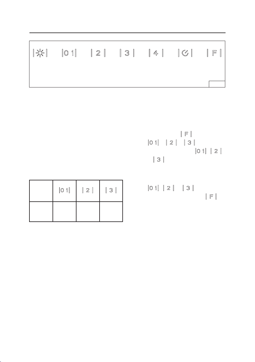
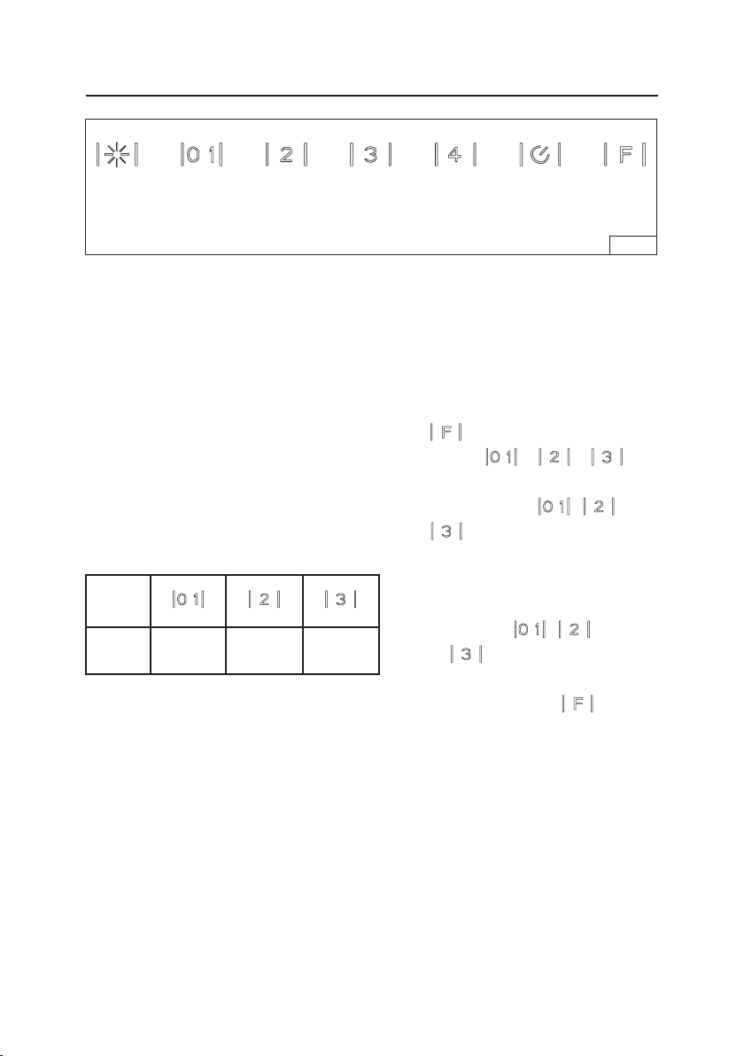
OPERATION
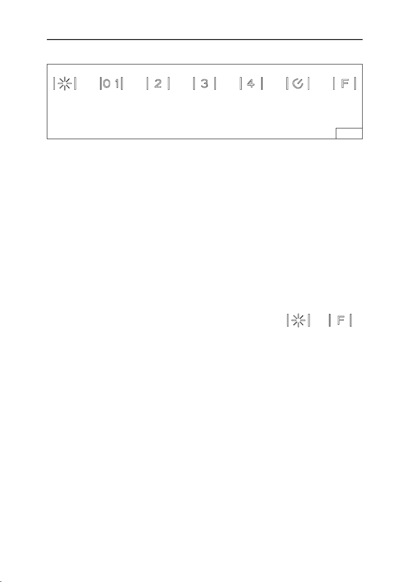
Controls (Fig. 1)
HEAT SENTRY™
Your hood is equipped with a HEAT SENTRY™ thermostat. This thermostat is a
device that will turn on or speed up the blower if it senses excessive heat above
the cooking surface.
1) If blower is OFF - it turns blower ON to HIGH speed.
2) If blower is ON at a lower speed setting - it turns blower up to HIGH speed.
When the temperature level drops to normal, the blower will return to its original setting.
WARNING
The HEAT SENTRY thermostat can start the blower even if the hood is turned OFF. When
this occurs, it is impossible to turn the blower OFF with its switch. If you must stop the
blower, do it from the main electrical panel.
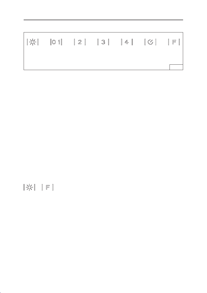
Light
Switch
Blower
On / Off
Blower
Speed 2
Time
Delay
FIG. 1
Blower
Speed 3
Blower
Speed 4
Filter
Reset
This range hood is equipped with the latest in capacitive touch technology. The buttons do
not move, but are touch-sensitive. When a touch is understood, the control will emit a sound.
Light Button turns the LED lights on and off. Push once to turn lights on. Push again to turn
lights off.
Blower On / Off button turns the blower on to low speed. Push a second time to turn blower off.
Blower Speed 2 button increases blower speed to medium-low speed.
Blower Speed 3 button increases blower speed to medium-high speed.
Blower Speed 4 button increases blower speed to high speed.
Delay button activates a delay off feature. Press once to activate the 5-minute delay off for any
of the blower speed settings. Press again to deactivate the time delay off.
Filter Reset lights after every 30 hours of operation, indicating a need to clean the filters. After
filters are cleaned or replaced, press once to reset the 30-hour timer.
Clean Mode deactivates controls for cleaning of glass. Press and hold and
for
5 seconds. Repeat to re-activate controls.
Auto Shut-Off Feature
If the blower and/or the lights are on continuously for 10 hours without any user interaction with
the controls, the hood will automatically shut off. Press any control button to re-activate the hood.

- 5 -
LED LAMPS
The hood is provided with LED lamps which require no maintenance.
CLEANING AND MAINTENANCE
Proper maintenance of the Range Hood will assure proper performance of the unit.
Motor
The motor is permanently lubricated and never needs oiling. If the motor bearings make excessive or
unusual noise, replace the motor with the exact service motor. The impeller should also be replaced.
Grease Filter
The grease filter should be cleaned frequently. Use a warm detergent solution. Grease filter is dishwasher
safe.
Clean all-metal filters in the dishwasher using a non-phosphate detergent. Discoloration of the filter may
occur if using phosphate detergents, or as a result of local water conditions - but this will not affect filter
performance. This discoloration is not covered by the warranty.
See “INSTALL FILTERS” section for removal and installation instructions.
Non-ducted Recirculation Filter
The non-ducted recirculation filter should be changed every 6 months. Replace more often if your
cooking style generates extra grease, such as frying and wok cooking. See “INSTALL FILTERS” section
for removal and installation instructions.
Stainless Steel Cleaning
DO:
• Regularly wash with clean cloth or rag soaked
with warm water and mild soap or liquid dish
detergent.
• Always clean in the direction of original polish
lines.
• Always rinse well with clear water (2 or 3 times)
after cleaning. Wipe dry completely.
• You may also use a specialized household
stainless steel cleaner.
DON’T:
•
Use any steel or stainless steel wool or any
other scrapers to remove stubborn dirt.
• Use any harsh or abrasive cleansers.
• Allow dirt to accumulate.
• Let plaster dust or any other construction
residues reach the hood. During construction/
renovation, cover the range hood to make sure
no dust sticks to the stainless steel surface.
Avoid: When choosing a detergent
• Any cleaners that contain bleach will attack stainless steel
• Any products containing: chloride, fluoride, iodide, bromide will deteriorate surfaces rapidly.
• Any combustible products used for cleaning such as acetone, alcohol, ether, benzol, etc., are highly
explosive and should never be used close to a range.

- 6 -
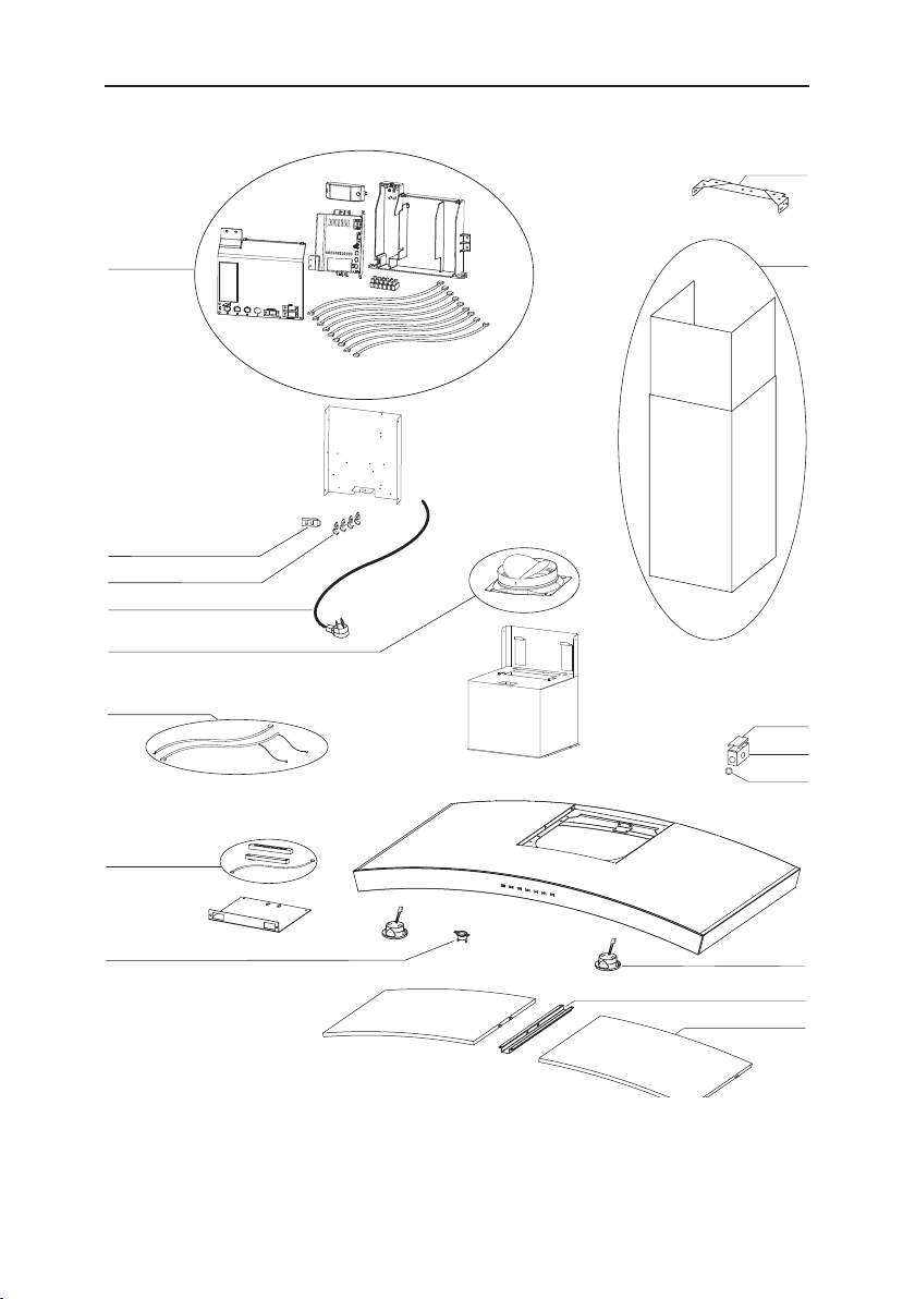
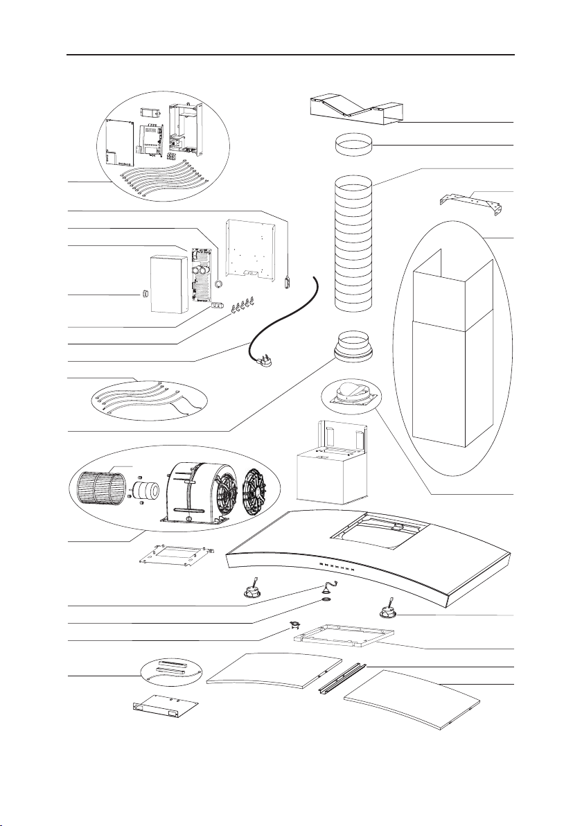
PREPARE THE HOOD
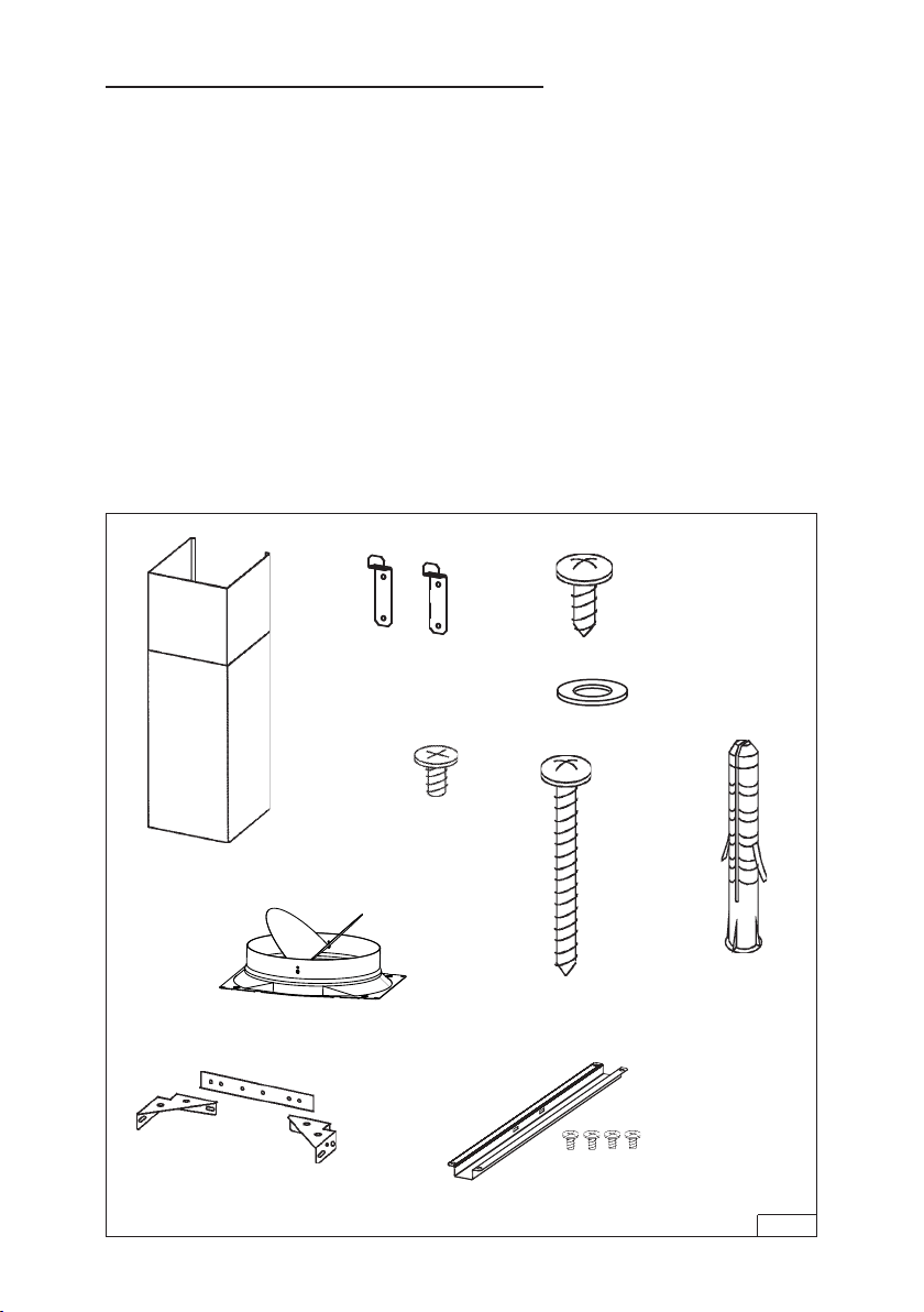
Unpack hood and check contents.
You should receive:
1 - Hood
1 - Decorative Flue Assembly
1 - Parts Bag containing:
2 - Mounting Brackets
1 - Damper Kit
1 - Flue Mounting Bracket Assembly
8 - Mounting Screws (4.8 x 38mm Pan Head)
4 - Mounting Screws (3.9 x 9.5mm Pan Head)
2 - Mounting Screws (3.9 x 6mm Flat Head)
8 - Drywall Anchors
2 - Flat Washers
1 - Filter Support
4 - Mounting Screws (4 x 8mm)
1 - Installation Instructions
MOUNTING
BRACKETS
FLUE MOUNTING BRACKET
8 MOUNTING SCREWS
(4.8 x 38mm Pan Head)
8 DRYWALL
ANCHORS
4 MOUNTING
SCREWS (3.9 x
9.5mm Pan Head)
DECORATIVE
FLUE
2 MOUNTING
SCREWS (3.9 x
6mm Flat Head)
FIG. 2
2 FLAT
WASHERS
DAMPER KIT
FILTER SUPPORT & (4)
MOUNTING SCREWS
(4 X 8mm)
- 7 -
EXTERIOR OR IN-LINE BLOWER SELECTION (WC35E)
CAUTION: Either an exterior blower or in-line blower may be used with this hood.
The hood must be installed with blower models EB6, EB9, EB12, EB15, ILB3,
ILB6, ILB9, or ILB11 only. Other Blowers cannot be substituted (Blowers sold
separately).
DECORATIVE
FLUE
8” ROUND
DUCT
INSTALL THE DUCTWORK
NOTE: To reduce the risk of fire, use only metal ductwork.
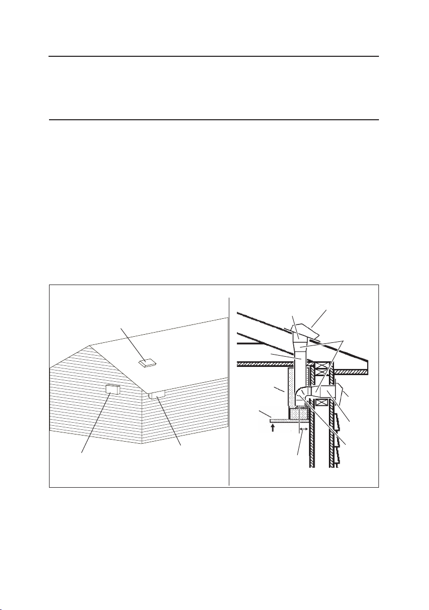
1. Choose the location where the Exterior or In-Line Blower will be mounted. See
illustrations below for mounting location suggestions and restrictions.
2. A straight, short duct run will allow the hood to perform most efficiently.
3. Long duct runs, elbows and transitions will reduce the performance of the
hood. Use as few of them as possible. Larger ducting may be required for best
performance with long duct runs.
4. After the Exterior or In-Line Blower has been installed, connect round metal
ductwork and work back towards the hood location. Use duct tape to seal joints
between ductwork sections.
5. An 8” round to 10” round transition (Model 414) is required. For best air
performance, install the transition as close to the range hood as possible.
OK
OK
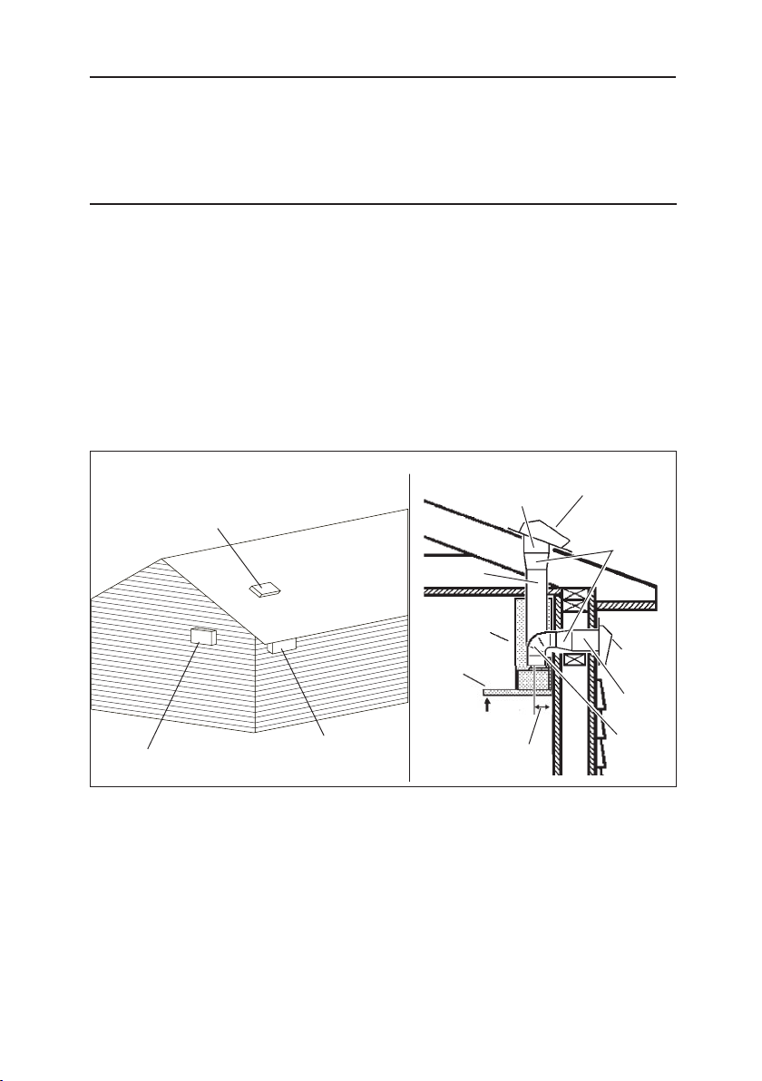
SUGGESTED MOUNTING LOCATIONS
EXTERIOR BLOWER
CAUTION: MAY NOT FIT
UNDER EAVES OF SINGLE
STORY HOMES
EXTERIOR
BLOWER
10” ROUND
DUCT
EXTERIOR
BLOWER
8” TO 10”
ROUND
TRANSITION
8” ROUND
ELBOW
10”
ROUND
DUCT
HOOD
24” TO 30” ABOVE
COOKING SURFACE
4¼” DISTANCE FROM
CENTERLINE OF DUCT
TO DRYWALL
- 8 -
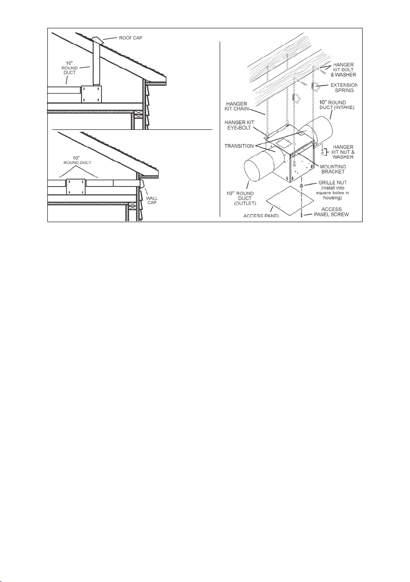
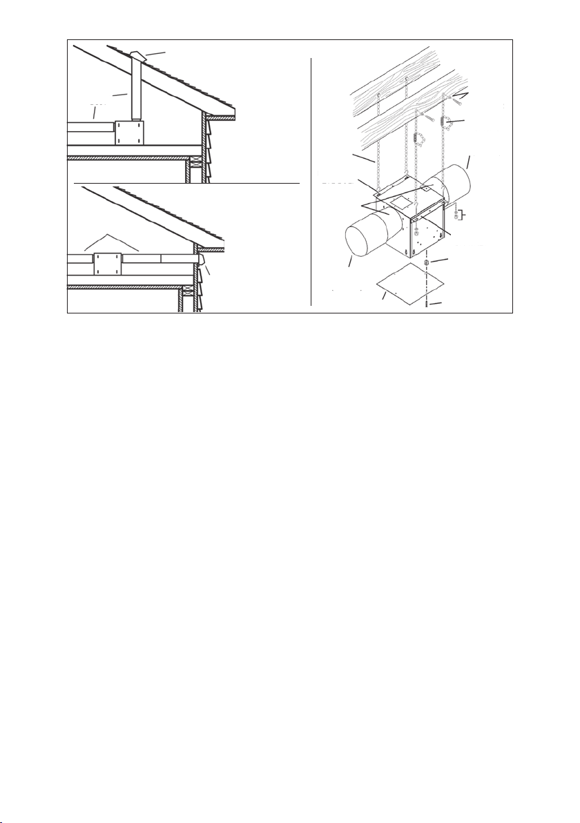
IN-LINE BLOWER
- 9 -
ROOF CAP
8-INCH
ROUND DUCT
DECORATIVE
FLUE
HOOD
WALL
CAP
8-INCH
ROUND
ELBOW
24” TO 30”
ABOVE
COOKING
SURFACE
(see “INSTALL
MOUNTING
BRACKETS”
section for
mounting
restrictions)
4¼”
DISTANCE
FROM
CENTERLINE
OF DUCT TO
DRYWALL
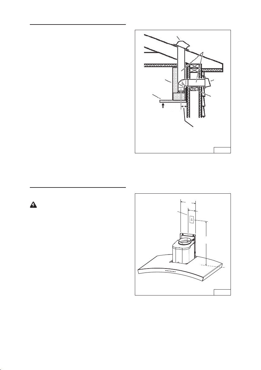
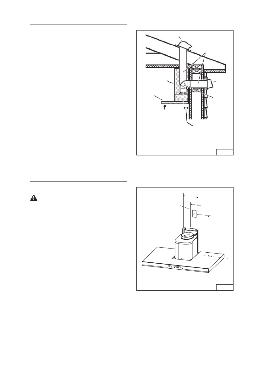
INSTALL THE DUCTWORK
DUCTED HOODS ONLY
CAUTION: To reduce the risk of fire, use
only metal ductwork.
1. Decide where the ductwork will run be-
tween the hood and the outside. Fig. 3.
2. A straight, short duct run will allow the
hood to perform most efficiently.
3. Long duct runs, elbows, and transitions
will reduce the performance of the hood.
Use as few of them as possible. Larger
ducting may be required for best perfor-
mance with longer duct runs.
4. Install a roof or wall cap. Connect round
metal ductwork to cap and work back
towards hood location. Use duct tape to
seal the joints between ductwork sections.
INSTALL ELECTRICAL
DUCTED and NON-DUCTED HOODS
WARNING : Electrical wiring must
be done by a qualified person(s) in ac-
cordance with all applicable codes and
standards. This range hood must be prop-
erly grounded. Turn off electrical power at
service entrance before wiring.
1. Plan where the hood will be located
above the cook top. Refer to the “INSTALL
MOUNTING BRACKET” section for hood
mounting height options.
2. Install a standard 2” x 4” wall outlet box
and 3-blade 125 volt, 15 Amp grounded
receptacle. Fig. 4.
3. Mount the center of the wall outlet 18½”
to 19½” above the bottom of the hood.
4. Locate the box and the receptacle within
boundary shown and off center of the
ductwork (to allow for power cord plug
and flue clearance).
FIG. 4
18½” to 19½”
4”
8”
CENTERLINE
OF HOOD
FIG. 3
- 10 -
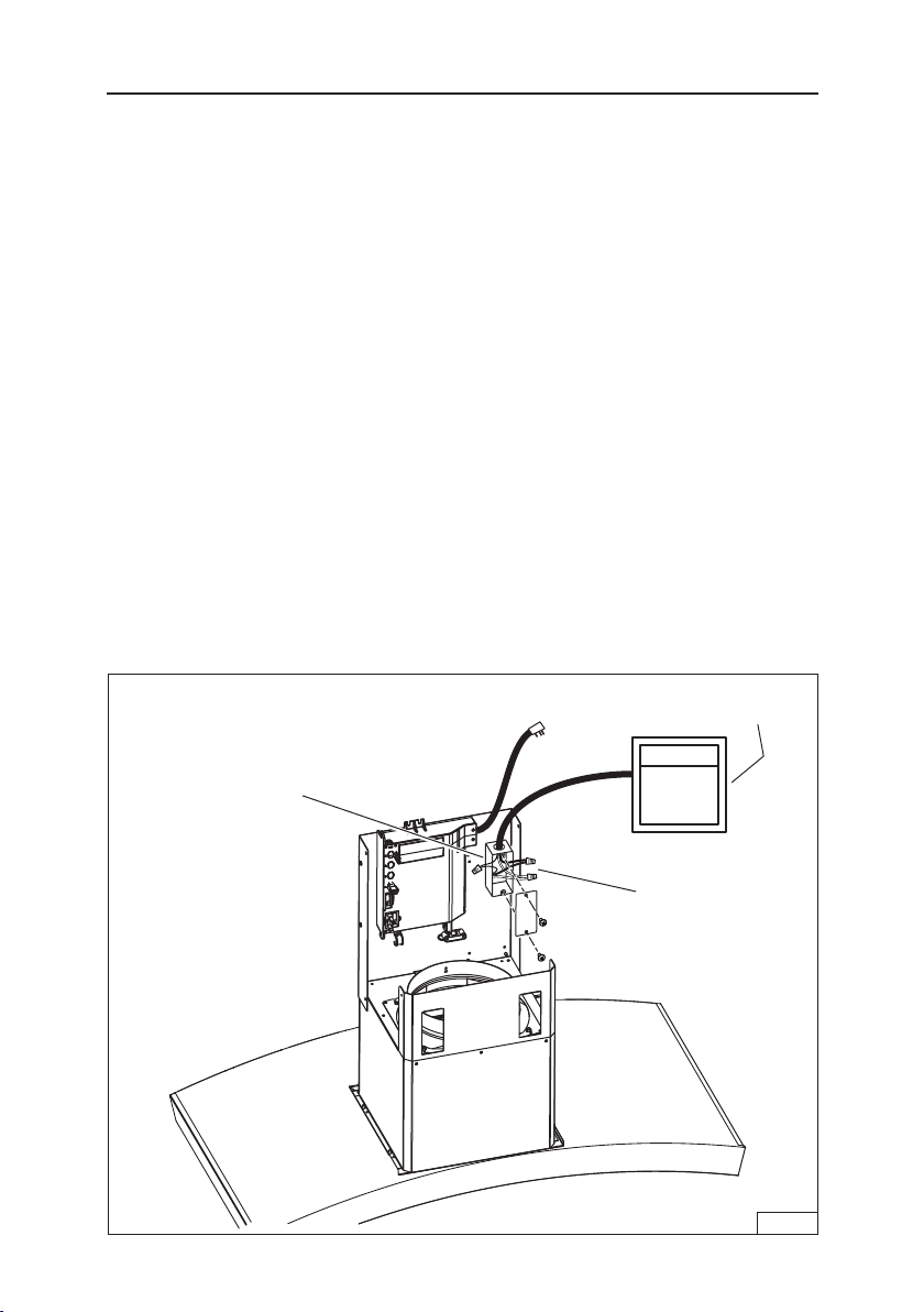
EXTERNAL BLOWER ELECTRICAL CONNECTIONS
Blower connection at hood:
1. Run 2-wire plus ground power cable from
the Exterior or In-Line Blower to the hood’s
wiring box marked “motor connection”.
2. Remove the cover from the wiring box and
remove one knockout.
3. Feed 6” of cable through the knockout
opening and secure the cable to the wiring
box with an appropriate connector.
4. Make electrical connections at the hood.
Connect white-to-white, red-to-black and
green-to-ground.
5. Replace the wiring box cover and screws.
make sure wires are not pinched between
the cover and box.
Exterior or In-line blower connection:
1. Make electrical connections at the exterior
or in-line blower (see instructions provided
with the exterior or in-line blower).
Power connection at hood:
1. Plug the power cord into the electrical wall
receptacle.
BLOWER CONNECTION AT HOOD
BOX MARKED
“MOTOR
CONNECTION”
CONNECT:
WHITE-TO-WHITE,
RED-TO-BLACK,
GREEN-TO-GROUND.
Exterior or
In-Line blower
FIG. 5
- 11 -
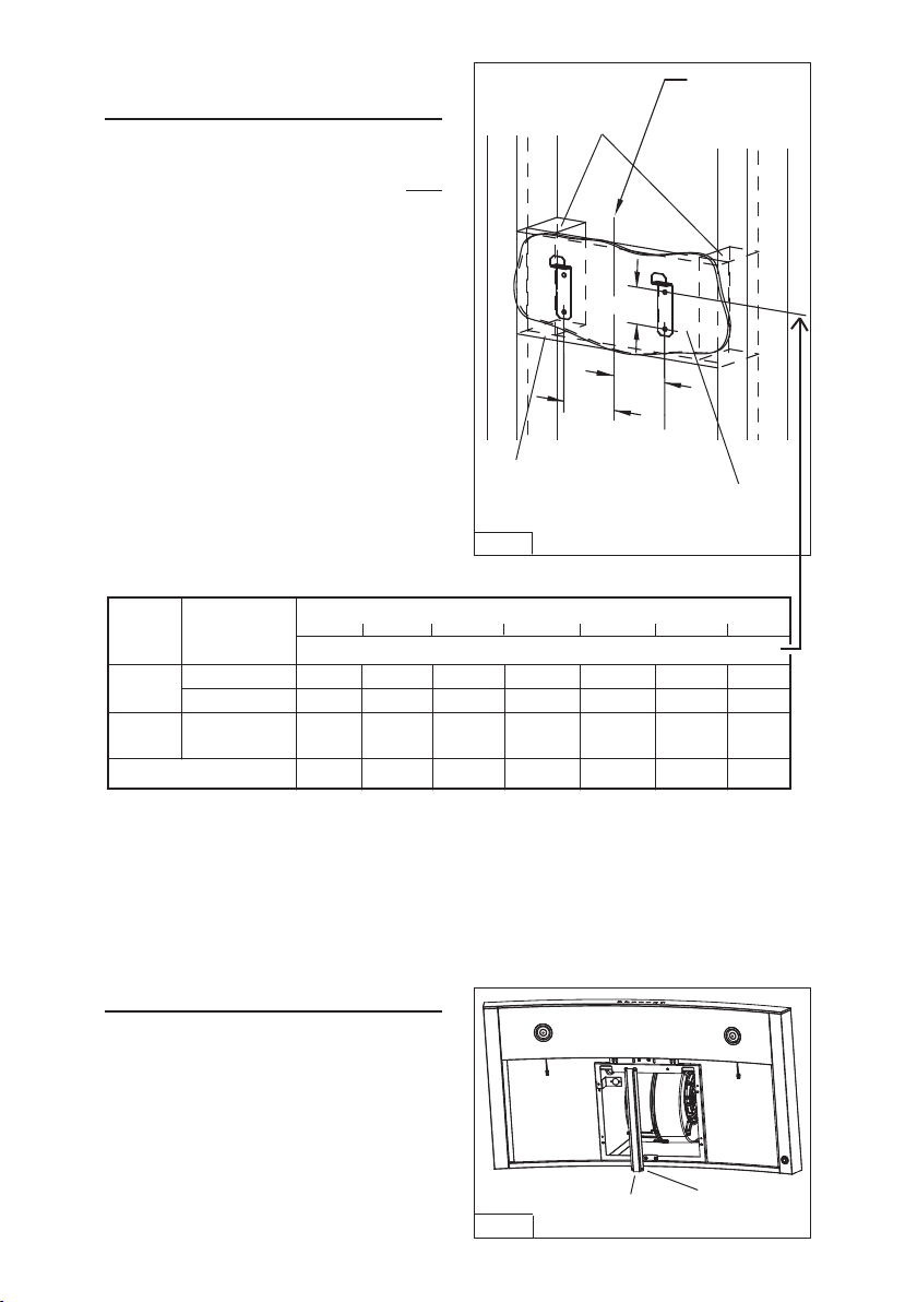
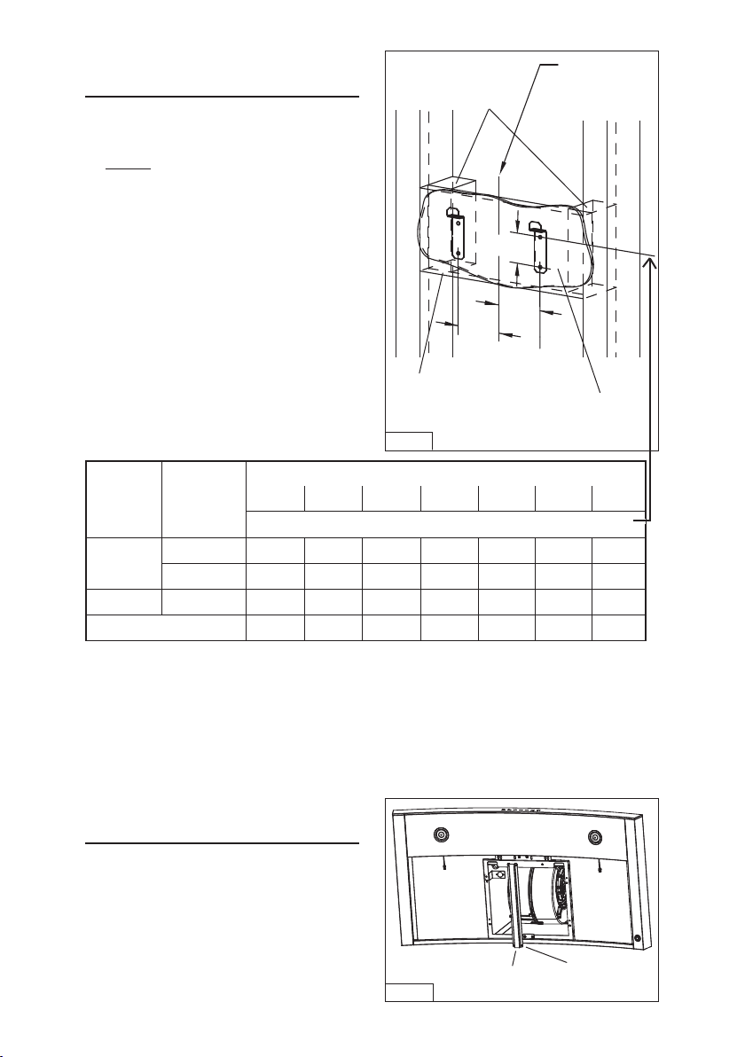
INSTALL MOUNTING
BRACKETS
DUCTED and NON-DUCTED HOODS
1. Construct wood wall framing that is flush
with interior surface of wall studs. Fig. 6.
Make sure:
a) the framing is centered over installa-
tion location.
b) the height of the framing will allow the
mounting brackets to be secured
to the framing within the dimensions
shown.
2. After wall surface is finished, secure
the mounting brackets to framing with (4)
4.8 x 38 mm mounting screws. See chart
below for mounting bracket location.
Notes:
a. Minimum hood distance above cook top must not be less than 24”. A maximun of 30” above
cook top is highly recommended for best capture of cooking impurities. Distances over 30”
are at the installer and user’s discretion; and if ceiling height and flue length permit.
b. Requires optional 10’ flue extension, ducted model AEWC345
IQSB or non-ducted model
AEWC345IQSBN.
HOOD DISTANCE ABOVE 36” HIGH COOK TOP (see note below)
30”
MOUNTING BRACKET CENTER HOLE LOCATION ABOVE 36” HIGH COOK TOP
CEILING
HEIGHT
8 FEET
24” 25” 26” 27” 28” 29”
37-7/8” 38-7/8” 39-7/8” 40-7/8”
9 FEET
41-7/8”
42-7/8” 43-7/8”
DUCTED
NON-DUCTED
DUCTED OR
NON-DUCTED
DUCT
METHOD
37-7/8” 38-7/8” 39-7/8” 40-7/8”
40-7/8” 41-7/8”
42-7/8” 43-7/8”
10 FEET (see note b.)
39-7/8” 40-7/8” 41-7/8”
42-7/8” 43-7/8”
37-7/8” 38-7/8”
INSTALL CENTER BRACKET
1. Install center bracket using (4) M4x8
screws. Fig. 7.
FIG. 7
(4) M4x8
SCREWS
CENTER
BRACKET
41-7/8”
42-7/8” 43-7/8”
WOOD CROSS
SUPPORT BEHIND
DRYWALL
DRYWALL
FIG. 6
FRAMING
BEHIND WOOD
CROSS SUPPORT
CENTERLINE
3-1/2”
3-1/2”
2-3/16”
---
---
---
- 12 -
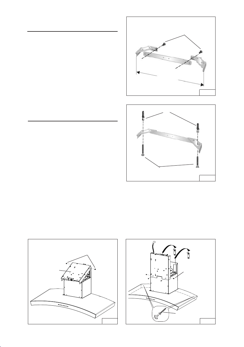
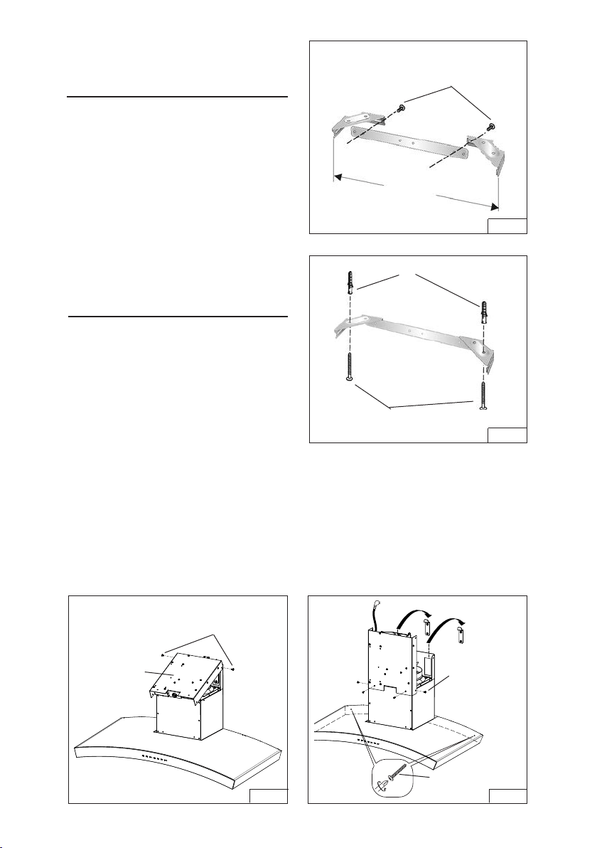
INSTALL FLUE MOUNTING
BRACKET
DUCTED AND NON-DUCTED HOODS
1. Assemble the flue mounting brack-
et, adjusting outside width as shown.
Fig. 8.
2. Carefully center the mounting bracket
directly over the range hood location.
3. Secure the bracket assembly to the
ceiling using (2) 4.8 x 38 mm mount-
ing screws and drywall anchors.
Fig. 9. Make sure the bracket is pushed
into the corner, tight against the wall and
centered over the hood.
FLUE MOUNTING BRACKET
11¾”
FIG. 8
3.9 x 6 mm FLAT HEAD
BRACKET SCREWS
FIG. 9
4.8x38mm
MOUNTING SCREWS
DRYWALL ANCHORS
FIG. 11
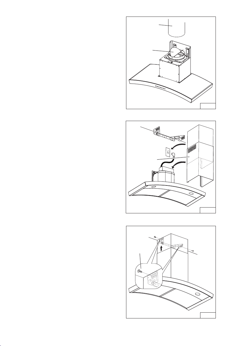
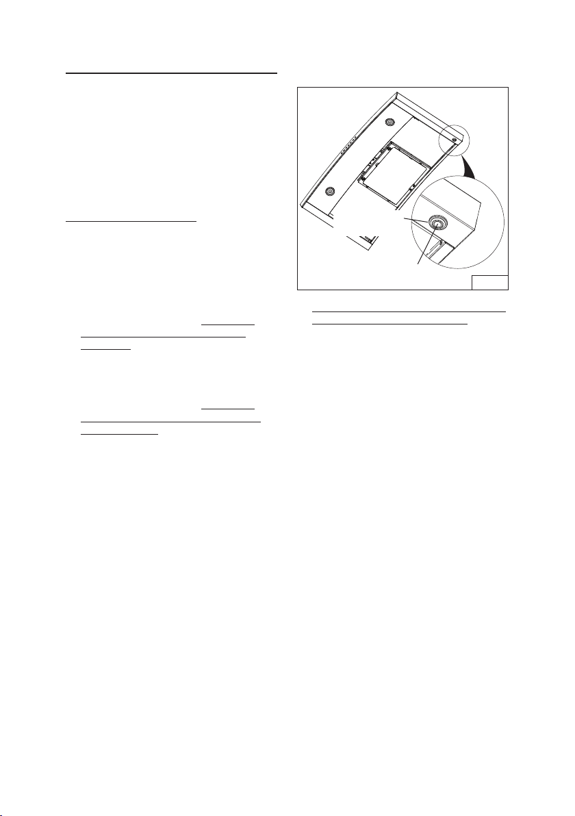
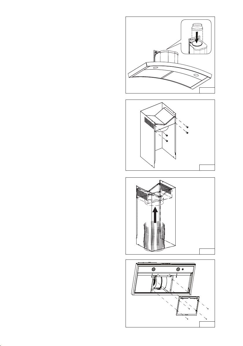
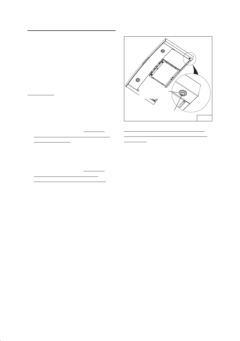
INSTALL THE HOOD
Note: Remove the plastic protective film
from all exterior surfaces, decorative
flues and filters, prior to final installation.
Remove filters. (Refer to the “Install Filters”
Section.)
DUCTED and NON-DUCTED INSTALLATION
1. Remove the electrical system box from
chimney frame by removing (2) 3.9 x 9.5 mm
screws. Fig. 10.
2. Attach electrical system box to frame using (2)
3.9 x 9.5 mm screws removed in Step 1 and
(2) 3.9 x 9.5 mm screws and (2) lock washers
from hardware bag.
3. Install hood onto the wall mounting brackets.
Fig. 11. Adjust leveling screws on mounting
brackets to level hood with floor.
3. Mark and install (2) additional screws as
shown. Use drywall anchors only if necessary.
ELECTRICAL
SYSTEM BOX
FIG. 10
REMOVE (2)
3.9 x 9.5 mm
SCREWS
4.8 x 38 mm
SCREWS
INSTALL (4)
3.9 x 9.5 mm
SCREWS &
LOCK WASHERS
ON (2) SCREWS
- 13 -
FIG.12
8-INCH DIA.
METAL DUCT
DUCTED INSTALLATION ONLY
Note: Rooms with 10-foot ceiling require
flue extension model AEWC345
I QSB,
available from your local dealer. Discard
the upper flue supplied with the range
hood and replace it with the longer flue
extension.
1. Remove protective tape from blower outlet
before installing damper to hood with
(4) screws supplied and tape joint with
aluminum duct tape. Fig. 12.
2. Run 8-inch diameter metal ductwork to
the outside location.
3. Install an appropriate wall or roof cap with
damper to exhaust the air to the outside.
4. Tape all duct joints with aluminum duct
tape.
5. Plug power cord into wall outlet. Fig. 13.
6. Install upper and lower decorative flues
onto the range hood.
- Vents are concealed on 8-foot
ceilings.
- Vents are exposed on 9-foot
ceilings.
7. Secure upper flue to flue mounting bracket
with (2) 3.9 x 6 mm screws. Fig. 14
FIG.13
FIG.14
DAMPER/
DUCT
CONNECTOR
CONCEALED
VENTS
CEILING
3.9 x 6mm
SCREWS
2

- 14 -
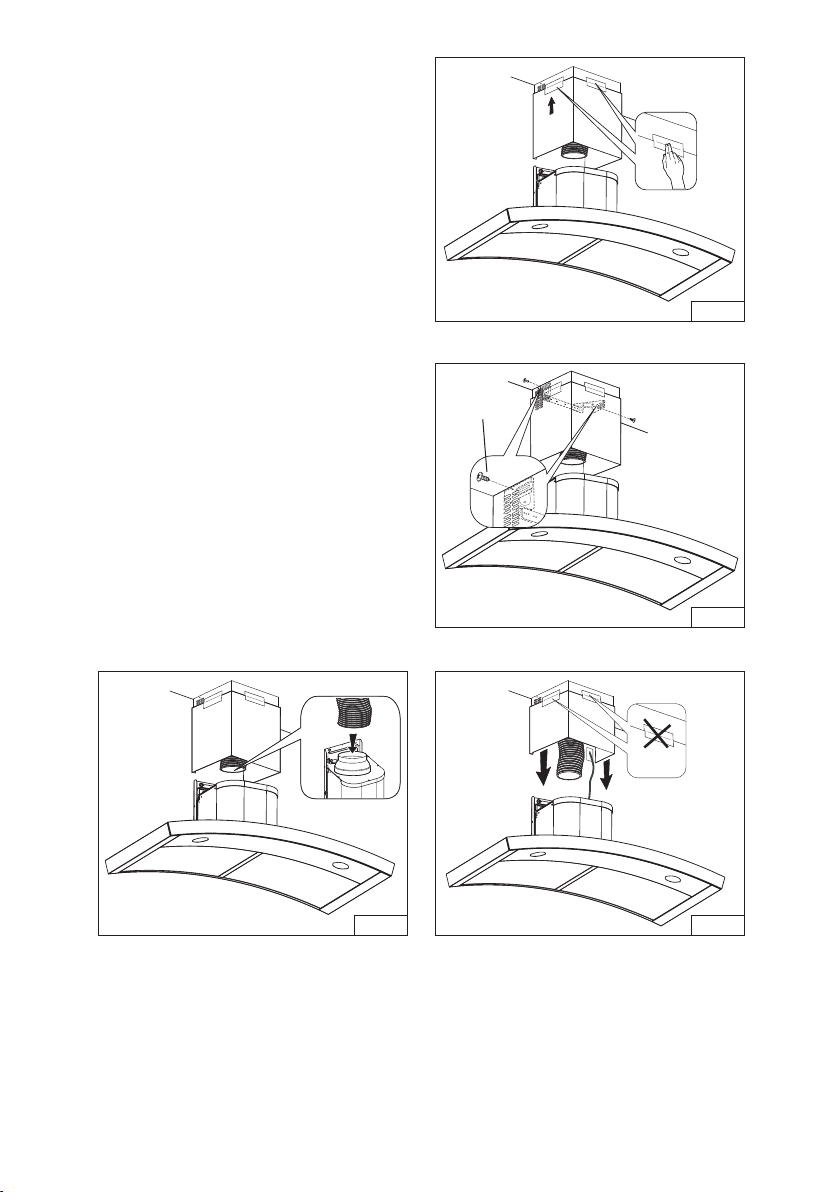
NON-DUCTED INSTALLATION ONLY
Note:
a. Purchase Model ANKWC345 Non-ducted
Recirculation Kit.
b. Rooms with 10-foot ceiling require flue
extension model AEWC345
IQSBN,
available from your local dealer. Discard
the upper flue supplied with the range
hood and replace it with the longer flue
extension.
1. Install discharge collar supplied with the
range hood. Fig. 15.
2. Attach the 6”-to-8” adapter to blower
discharge and tape joint with aluminum
duct tape. Fig. 15.
3. Install the plenum to the upper decorative
flue using (4) 3.4 x 15 mm screws
provided as shown. Fig. 16.
4. Attach 6-inch expandable ducting to the
plenum and tape joint with aluminum duct
tape. Fig. 17.
5. Attach non-duct filter frame using (4) 3.9
x 6 mm screws. Fig. 18.
FIG.15
FIG.16
FIG.17
3.9 x 6mm
SCREWS
FIG.18
- 15 -
6. Temporarily secure the upper and lower
flue together with duct tape as shown. Fig.
19.
7. Lift the flue into position above the hood.
Secure upper flue to the flue mounting
bracket with (2) 3.9 x 6 mm screws. Fig.
20.
8. Stretch expandable duct, attach it to the
6”-to-8” adapter and tape duct joints. Fig.
2 1.
9. Plug power cord into wall outlet.
10. Remove tape from flues and lower into
position on the hood. Fig. 22.
FIG.20
FIG.19
FIG.21 FIG.22
3.9 x 6mm
SCREWS
2
- 16 -
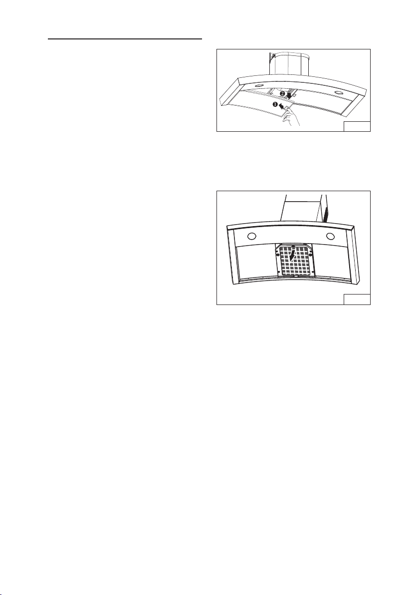
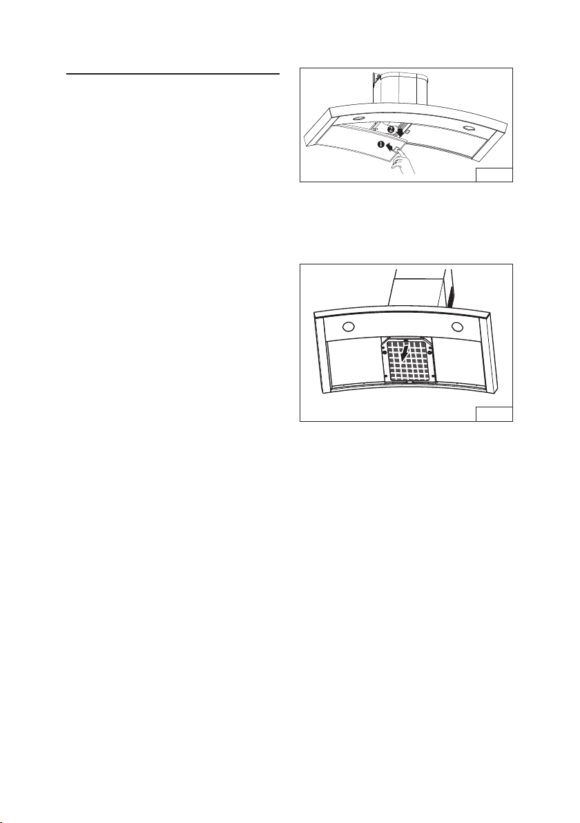
INSTALL FILTERS
DUCTED AND NON-DUCTED HOODS
1. To remove the GREASE filter, pull down
latch tab to disengage the filter from the
hood. Tilt the filter downward and remove.
Fig. 23.
2. To install the GREASE filter, align rear filter
tabs with slots in the hood. Pull down latch
tab, push filter into position and release.
Make sure the filter is securely engaged
after installation. Fig. 24.
NOTE: Prior to use, remove protective film
from the filter frame.
NON-DUCTED HOODS ONLY
1. To remove the CHARCOAL filter, grip and
push filter tab toward rear of hood. Pull the
filter down to disengage the rear filter tabs.
Fig. 23.
2. To install the CHARCOAL filter, align filter
in rectangular opening. Push filter against
springs in rear of hood and press into place.
Make sure the filter is securely engaged
after assembly.
3. Install GREASE filter after charcoal filter
is installed.
FIG.23
FIG.24
- 17 -
CALIBRATE IQ BLOWER
SYSTEM
TM
INTERNAL BLOWER DUCTED UNITS ONLY
After the hood is installed and wired,
engage the calibration process (our
Guaranteed Performance System
Technology to ensure full-rated airflow is
being delivered). Prior to calibration, ensure
that all filters, light bulbs and duct system
are installed.
CALIBRATION PROCESS Fig. 25.
Hold the calibration button for 3 seconds;
calibration button will light up and stay on
for up to 13 minutes. The blower will start
and begin the calibration process. When
calibration is complete, one of two things
will occur:
1. The blower turns off and calibration
button light stays on = Successful
calibration. Press the button to turn off
the LED. Note: The LED will also turn off
if you select any blower speed on the
control.
2. The blower turns off and calibration
button light blinks continuously = Too
much restriction in the ductwork is
preventing the IQ Blower System™ from
achieving the rated airflow. The blower is
automatically set to maximum intensity.
NOTE: Common items that cause
restrictions: restricted damper flap
(backdraft damper, wall cap, roof cap),
too many elbows, duct size less than
80% of hood outlet, poor transition, use
of flex ducting and/or crushed ducting.
FIG.25
CALIBRATION
BUTTON
CALIBRATION
LIGHT
Three options are available if your hood
system has too much restriction:
1. Accept airflow as is.
a. Press the calibration button to
accept airflow as is. The IQ Blower
System™ is now configured to the
highest possible performance. The
blinking calibration light goes out.
Note: The LED will also turn off if
you select any blower speed on
the control.
2. Correct duct restriction, clear the
original calibration data, and repeat
the calibration process.
a. Correct the duct restriction.
b. Clear the original calibration data
by holding calibration button for
10 seconds. The light will blink 3
times to confirm and the blower
configuration will go back to default
settings.
c. Repeat calibration process from
the beginning.
3. Clear calibration data to reset hood
to default factory setting and achieve
standard high pressure blower
performance.
a. Clear calibration data and reset
hood to factory default setting
by holding calibration button for
10 seconds. The light will blink 3
times to confirm and the blower
configuration will go back to default
settings.
- 18 -
The range hood is designed to work with
several different blower models. Before
using, the control must first be programmed
to your blower model, in order to achieve
proper operating speeds.
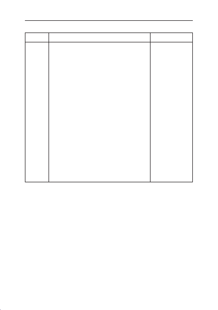
From the chart below:
1. Find the SETUP number that
corresponds to the blower model that is
installed with your range hood.
2. The control is factory-preset to SETUP
3. If your blower model is listed under
SETUP 3, no programming is required
and the range hood is ready to use.
SETUP SETUP SETUP
(default)
BLOWER
MODEL
NUMBER
EB6
ILB3
ILB6
EB12
EB15
ILB9
EB9
ILB11
3. To program blower models listed under
SETUP 1 and 2:
A) Power must be supplied to the
hood. The blower and lights must be
turned off.
B) Press and hold
for 5 seconds.
+
+
will flash 3
times. After 1 second, ,
or will light up to indicate the
current setting.
C) Select the proper SETUP for your
blower from the chart at left. Press
, or to select the
proper SETUP. Then press to
confirm and store the new setting.
D) The range hood is now ready to use.
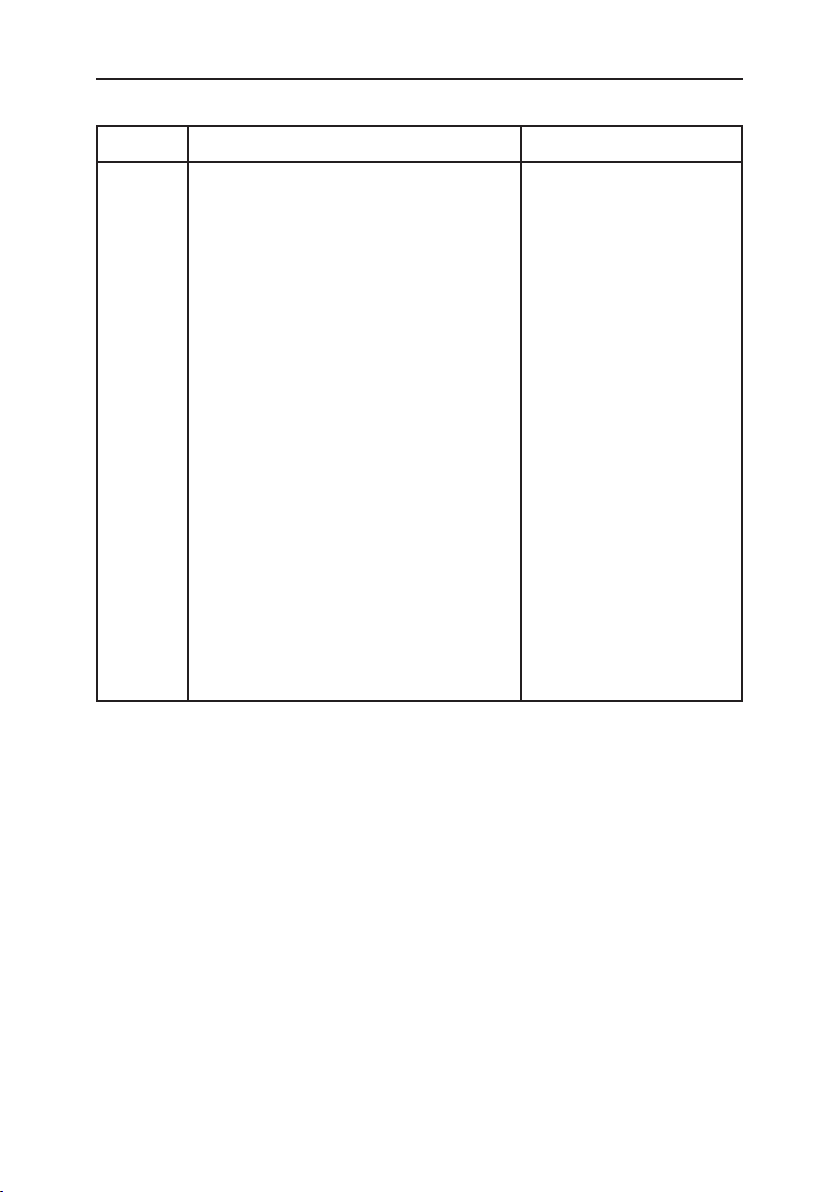
EXTERNAL BLOWER
PROGRAMMING MODE PROCEDURE (WC35E)
Light
Switch
Blower
On / Off
Blower
Speed 2
Time
Delay
FIG. 26
Blower
Speed 3
Blower
Speed 4
Filter
Reset
- 19 -
SERVICE PARTS
WC35IQ SERIES
KEY NO. DESCRIPTION PART NO.
CAS BLOWER ASSEMBLY 06002259
49 FAN (CLOCK WISE) 03295071
IME ELECTRICAL INSTALLATION ASSEMBLY 06145222
114 WIRE CLAMP 032904990
506 BLDC DRIVER 97019431
67 WIRES 06102592
202 REFLECTOR STOP 03292290
415 FAIRLEAD 03202288
60 FEEDER CABLE 02300249
415 FAIRLEAD 03202288
37 KNOB 02300804
474 LED LAMP 08093413
AQI SWITCH BOX ASSEMBLY 06102590
439 STOP RING 02320034
507 ASSEMBLY CALIBRATION BUTTON 06102584
195 BRACKET E3351078
9 GREASE FILTER 08087823
ARU CONNECTION AIR OUTLET SET 080810849
485 TELESCOPIC DUCT KIT 08016368
120 FLUE MOUNTING BRACKET 08091851
195 CENTER BRACKET E3351078
122 NON-DUCT PLENUM 08093478
86 6” ADAPTER RING 032292300
503 6” EXPANDABLE DUCT 02011557
58 8” TO 6” REDUCER 03294170
NON-DUCT FILTER 08999176
HARDWARE BAG 080810993

- 20 -
SERVICE PARTS
WC35IQ SERIES
474
485
64
US-DUNE HS BLDC
195
CAS
IME
506
202
60
202
415
(03202288)
415
(03202288)
49
114
AQI
9
120
503
86
122
67
ARU
439
37
507
58
- 21 -
SERVICE PARTS
WC35E SERIES
KEY NO. DESCRIPTION PART NO.
IME ELECTRICAL INSTALLATION ASSEMBLY 06145223
166 ELECTRICAL PRINTED CIRCUIT BOARD 08080877
145 FEEDER CABLE CONNECTION BOX 032920170
147 JUNCTION CLAMP R2300132
146 FEEDER CABLE CONNECTION BOX COVER 03292180
151 ELECTRICAL BOX WIRES STOP 032920200
114 WIRE CLAMP 032904990
67 WIRES 06102593
60 FEEDER CABLE 02300249
37 KNOB 02300804
474 LED LAMP 08093413
AQI SWITCH BOX ASSEMBLY 06102591
195 BRACKET E3351078
9 GREASE FILTER 08087823
ARU CONNECTION AIR OUTLET SET 080810849
485 TELESCOPIC DUCT KIT 08016368
120 FLUE MOUNTING BRACKET 08091851
195 CENTER BRACKET E3351078
HARDWARE BAG 080810993
- 22 -
SERVICE PARTS
WC35E SERIES
US-DUNE HS EXT BLDC
474
195
AQI
9
37
485
IME
120
67
ARU
116
115
415
202
60
114
- 23 -
99045142C
WARRANTY
ONE YEAR LIMITED WARRANTY FOR BEST PRODUCTS
Broan-NuTone LLC (Broan-NuTone) warrants to the original consumer purchaser of Best products that such products
will be free from defects in materials or workmanship for a period of one year from the date of original purchase. THERE
ARE NO OTHER WARRANTIES, EXPRESS OR IMPLIED, INCLUDING, BUT NOT LIMITED TO, IMPLIED WARRAN-
TIES OR MERCHANT ABILITY OR FITNESS FOR A PARTICULAR PURPOSE.
During this one-year period, Broan-NuTone will, at its option, repair or replace, without charge, any product or part which
is found to be defective under normal use and service.
THIS WARRANTY DOES NOT EXTEND TO FLUORESCENT LAMP STARTERS, TUBES, HALOGEN AND INCANDES-
CENT BULBS, FUSE, FILTERS, DUCTS, ROOF CAPS, WALL CAPS AND OTHER ACCESSORIES FOR DUCTING.
This warranty does not cover (a) normal maintenance and service or (b) any products or parts which have been subject
to misuse, negligence, accident, improper maintenance or repair (other than by Broan-NuTone), faulty installation or
installation contrary to recommended installation instructions.
The duration of any implied warranty is limited to the one-year period as specified for the express warranty. Some states
do not allow limitation on how long an implied warranty lasts, so the above limitation may not apply to you.
BROAN-NUTONE’S OBLIGATION TO REPAIR OR REPLACE, AT BROAN-NUTONE’S OPTION, SHALL BE THE
PURCHASER’S SOLE AND EXCLUSIVE REMEDY UNDER THIS WARRANTY. BROAN-NUTONE SHALL NOT BE LI-
ABLE FOR INCIDENTAL, CONSEQUENTIAL OR SPECIAL DAMAGES ARISING OUT OF OR IN CONNECTION WITH
PRODUCT USE OR PERFORMANCE. Some states do not allow the exclusion or limitation of incidental or consequential
damages, so the above limitation or exclusion may not apply to you.
This warranty gives you specific legal rights, and you may also have other rights, which vary from state to state. This
warranty supersedes all prior warranties.
To qualify for warranty service, you must (a) notify Broan-NuTone at the address stated below or telephone number stated
below, (b) give the model number and part identification and (c) describe the nature of any defect in the product or part.
At the time of requesting warranty service, you must present evidence of the original purchase date.
In USA - Best®, 926 W. State Street, Hartford, WI 53027 (800-558-1711)
In Canada - Best®, 550 Lemire Blvd., Drummondville, QC J2C 7W9 (866-737-7770)
www.BestRangeHoods.com

- 24 -
Série WC35
ENGLISH.....................................2
FRANÇAIS.................................24
ESPAÑOL.................................. 47
Aux États-Unis - BEST Hartford, Wisconsin
Au CANADA - BEST Drummondville, QC, Canada
ENREGISTREZ VOTRE PRODUIT EN LIGNE À : www.BestRangeHoods.com/register
Pour de plus amples informations, visitez www.BestRangeHoods.com

- 25 -
LIRE CES DIRECTIVES ET LES CONSERVER
AVERTISSEMENT
OBSERVEZ LES DIRECTIVES CI-DESSOUS AFIN DE RÉDUIRE LES RISQUES D’INCENDIE,
DE CHOC ÉLECTRIQUE OU DE BLESSURES CORPORELLES :
1. N’utilisez cet appareil que de la manière prévue par le fabricant. Si vous avez des questions,
communiquez avec le fabricant à l’adresse ou au numéro de téléphone indiqués dans la garantie.
2. Avant de procéder à la réparation ou à l’entretien de l’appareil, coupez l’alimentation du
panneau électrique et verrouillez l’interrupteur principal afin d’empêcher que le courant ne soit
accidentellement rétabli. S’il est impossible de verrouiller l’interrupteur principal, fixez solidement
un message d’avertissement, par exemple une étiquette, sur le panneau électrique.
3. La pose de l’appareil et les travaux d’électricité doivent être effectués par des personnes qualifiées
conformément à la réglementation en vigueur, notamment les normes de la construction ayant
trait à la protection contre les incendies.
4. Pour éviter les refoulements, l’apport d’air doit être suffisant pour brûler les gaz produits par
les appareils à combustion et les évacuer dans le conduit de fumée (cheminée). Respectez les
directives du fabricant de l’appareil de chauffage et les normes de sécurité, notamment celles
publiées par la National Fire Protection Association (NFPA), l’American Society for Heating,
Refrigeration and Air Conditioning Engineers (ASHRAE) et les codes des autorités locales.
5. Veillez à ne pas endommager le câblage électrique ou d’autres équipements non apparents lors
de la découpe ou du perçage du mur ou du plafond.
6. Les ventilateurs canalisés doivent toujours rejeter l’air à l’extérieur.
7. N’utilisez pas de commande de régime à semi-conducteurs conjointement avec cet appareil.
8. Pour réduire les risques d’incendie, utilisez seulement des conduits en métal.
INSTRUCTIONS DE MISE À LA TERRE
Cet appareil doit être correctement mis à la terre. Dans l’éventualité d’un court-circuit, la mise à la
terre réduit les risques de décharge électrique en permettant au courant de s’échapper dans un fil.
Cet appareil comporte un cordon électrique muni d’un fil et d’une fiche de mise à la terre. Cette fiche
doit être branchée dans une prise de courant correctement installée et mise à la terre.
AVERTISSEMENT - Une mise à la terre incorrecte peut entraîner un risque de choc électrique.
Consultez un électricien qualifié si vous ne comprenez pas complètement les directives de mise àla
terre ou si vous n’êtes pas sûr que l’appareil comporte une mise à la terre adéquate.
N’utilisez pas de rallonge électrique. Si le cordon électrique est trop court, demandez à un électricien
qualifié d’installer une prise de courant près de l’appareil.
!
POUR USAGE DOMESTIQUE SEULEMENT
!
- 26 -
!
ATTENTION
1. Pour usage intérieur seulement.
2. Pour réduire les risques d’incendie et évacuer l’air correctement, assurez-vous qu’il est canalisé
à l’extérieur. N’évacuez pas l’air dans des espaces enfermés par des murs ou un plafond ou
dans un grenier, un vide sanitaire ou un garage.
3. Faites attention lorsque vous utilisez des agents nettoyants ou des détergents.
4. Évitez d’utiliser des produits alimentaires pouvant produire des flammes sous la hotte.
5. Pour ventilation générale uniquement. N’utilisez pas cet appareil pour évacuer des matières
ou des vapeurs dangereuses ou explosives.
6. Pour éviter d’endommager les roulements de moteur, de déséquilibrer les pales ou de les
rendrebruyantes, débarrassez l’appareil de la poussière de plâtre, de construction, etc.
7. Le moteur de la hotte est muni d’un dispositif de protection thermique qui coupe automatiquement
le moteur en cas de surchauffe. Il se remet en marche lorsqu’il a refroidi. Faites réparer la hotte
si le moteur continue à fonctionner par intermittence.
8. Pour mieux capter les vapeurs de cuisson, le bas de la hotte doit être au minimum à 61 cm
(24 po) et au maximum à 76,2 cm (30 po) de la surface de cuisson. Pour les restrictions
s’appliquant au montage, voir la section « Installation de la bride de montage ».
9. Il est recommandé d’avoir deux installateurs, compte tenu de la taille et du poids de cette hotte.
10. Ce produit est doté d’un thermostat qui peut faire démarrer automatiquement le ventilateur.
Pourréduire les risques de blessures, coupez l’alimentation sur le panneau électrique et verrouillez-
le ou accrochez-y une étiquette de manière à éviter que le courant ne soit rétabli par accident.
11. Veuillez lire l’étiquette de spécifications du produit pour obtenir plus de renseignements,
notamment sur les exigences.
12. MODÈLES VENTILATEUR EXTERNE SEULEMENT : Pour réduire les risques d’incendie et de
choc électrique, installez cette hotte uniquement avec un ventilateur extérieur Best de modèle
EB6, EB9, EB12 ou EB15 ou un ventilateur intermédiaire Best de modèle ILB3, ILB6, ILB9 ou
ILB11. Ne pas leur substituer un autre ventilateur. Ventilateursvendus séparément.
AVERTISSEMENT
POUR RÉDUIRE LES RISQUES D’INCENDIE CAUSÉS PAR DE LA GRAISSE SUR LE PLAN
DE CUISSON :
A. Ne laissez jamais les éléments de surface allumés à haute température. Les débordements
peuvent causer de la fumée et occasionner des écoulements de graisse inflammables. L’huiledoit
être chauffée graduellement à basse ou à moyenne température.
B. Mettez toujours la hotte en MARCHE lors de la cuisson à feu vif ou lors de la cuisson d’aliments
à flamber (par ex., crêpes Suzette, cerises jubilé, bœuf au poivre flambé).
C. Nettoyez souvent la hotte. Ne laissez pas la graisse s’accumuler sur le ventilateur ou les filtres.
D. Utilisez des casseroles de dimension appropriée. Utilisez toujours une batterie de cuisine adaptée
à la dimension de la surface chauffante.
OBSERVEZ LES CONSIGNES SUIVANTES DE MANIÈRE À RÉDUIRE LES RISQUES DE
BLESSURES CORPORELLES EN CAS D’INCENDIE CAUSÉ PAR DE LA GRAISSE SUR LE
PLAN DE CUISSON :*
1. ÉTOUFFEZ LES FLAMMES à l’aide d’un couvercle étanche, d’une tôle à biscuits ou d’un plateau
en métal puis éteignez le brûleur. FAITES ATTENTION DE NE PAS VOUS BRÛLER. Si les
flammes ne s’éteignent pas immédiatement, QUITTEZ LES LIEUX ET APPELEZ LE SERVICE
DES INCENDIES.
2. NE SOULEVEZ JAMAIS UNE CASSEROLE EN FLAMMES – vous pourriez vous brûler.
3. N’UTILISEZ PAS D’EAU, ni de serviettes ou de linges mouillés – une violente explosion de vapeur
pourrait survenir.
4. Utilisez un extincteur SEULEMENT si :
A. Vous savez qu’il est de classe ABC et vous connaissez déjà son mode de fonctionnement.
B. L’incendie n’est pas très important et ne se propage pas.
C. Les pompiers ont été avisés.
D. Vous pouvez combattre l’incendie en faisant dos à une sortie.
* Conseils tirés de la publication de la NFPA « Kitchen Fire Safety Tips ».
- 27 -
FONCTIONNEMENT
Commandes (Fig. 1)
THERMOSTAT HEAT SENTRY
MC
Votre hotte est équipée d’un thermostat HEAT SENTRY
MC
. Ce dispositif actionne ou accélère
le ventilateur s’il détecte une chaleur excessive au-dessus de la surface de cuisson.
1) Si le ventilateur est ARRÊTÉ, il le met en MARCHE au régime ÉLEVÉ.
2) Si le ventilateur est en MARCHE à basse vitesse, il l’accélère au régime ÉLEVÉ.
Une fois la température revenue à la normale, le ventilateur revient à son réglage d’origine.
AVERTISSEMENT
Le thermostat HEAT SENTRY peut faire démarrer le ventilateur même si la hotte
estARRÊTÉE. Lorsque cela se produit, il est impossible d’ARRÊTER le ventilateur avec
son interrupteur. Si vous devez arrêter le ventilateur, coupez le disjoncteur du panneau
d’alimentation électrique.
Bouton
d’éclairage
Ventilateur
Marche / Arrêt
Ventilateur
Régime 2
Minuterie
FIG. 1
Ventilateur
Régime 3
Ventilateur
Régime 4
Alerte
filtre
Cette hotte est munie de la technologie capacitive tactile la plus récente. Les boutons ne bougent
pas mais sont sensibles au toucher. Lorsqu’un contact tactile est enregistré, lacommande
émet un son.
Le bouton Éclairage allume et éteint les lumières DEL. Appuyez une fois sur ce bouton pour
allumer les lumières. Appuyez de nouveau pour éteindre les lumières.
Le bouton Ventilateur Marche/Arrêt fait démarrer le ventilateur à son régime le plus lent.
Appuyez de nouveau pour arrêter le ventilateur.
Le bouton Ventilateur Régime 2 augmente la vitesse du ventilateur au régime lent-moyen.
Le bouton Ventilateur Régime 3 augmente la vitesse du ventilateur au régime moyen-rapide.
Le bouton Ventilateur Régime 4 augmente la vitesse du ventilateur au régime élevé.
Le bouton Minuterie actionne la fonction d’arrêt différé. Appuyez une fois pour activer l’arrêt
différé de 5 minutes, quelle que soit la vitesse du ventilateur. Appuyez de nouveau pour
désactiver la minuterie.
Le bouton Alerte filtre s’allume après 30 heures de fonctionnement pour indiquer qu’il est
temps de nettoyer les filtres. Une fois les filtres nettoyés ou remplacés, appuyez une fois sur
ce bouton pour réamorcer l’alerte de filtre.
Mode de nettoyage désactive les contrôles pour le nettoyage du verre. Appuyez et maintenez
et pendant 5 secondes. Répéter pour réactiver les contrôles.
Fonction d’arrêt automatique
Si le ventilateur ou l’éclairage reste continuellement allumé pendant 10 heures sans que
l’utilisateur interagisse avec les commandes, la hotte s’arrêtera automatiquement. Appuyez
sur tout de bouton de commande pour remettre la hotte en marche.

- 28 -
AMPOULES DEL
Cette hotte comprend des ampoules DEL qui n’exigent aucun entretien.
NETTOYAGE ET ENTRETIEN
Un entretien adéquat de la hotte assurera son bon fonctionnement.
Moteur
Le moteur est lubrifié en permanence et n’a pas besoin d’être huilé. Si les roulements du moteur sont
anormalement bruyants, remplacez le moteur exactement par le même modèle. La roue à ailettes doit
aussi être remplacée.
Filtre à graisses
Le filtre à graisses doit être nettoyé fréquemment. Utilisez une solution tiède de détergent. Le filtre à
graisses est lavable au lave-vaisselle.
Nettoyez les filtres entièrement métalliques au lave-vaisselle avec un détergent sans phosphate.
Unedécoloration du filtre peut se produire si des détergents phosphatés sont utilisés et selon les
conditions locales de l’eau, sans toutefois affecter le rendement du filtre. Cette décoloration n’est pas
couverte par la garantie.
Voir la section « INSTALLATION DES FILTRES » pour leur enlèvement et leur pose.
Filtre de recirculation pour installation sans conduits
Dans une installation sans conduit, le filtre de recirculation doit être remplacé tous les six mois.
Remplacez-le plus souvent si le type de cuisine produit plus de graisses, telle que la friture et la cuisson
au wok. Voir la section « INSTALLATION DES FILTRES » pour leur enlèvement et leur pose.
Nettoyage de l’acier inoxydable
À FAIRE :
• Régulièrement, nettoyez toutes les surfaces
avec un chiffon propre imbibé d’eau tiède et
de savon doux ou de liquide à vaisselle.
• Nettoyez toujours dans le sens des lignes du
poli original.
• Rincez toujours à l’eau propre (2 ou 3 fois)
après le nettoyage. Séchez complètement
enessuyant.
• Vous pouvez également utiliser un nettoyant
spécial pour acier inoxydable.
À NE PAS FAIRE :
•
N’utilisez pas de laine d’acier ordinaire ni de
laine d’acier inoxydable ou tout genre de grattoir
pour déloger la saleté.
• N’utilisez aucun nettoyant puissant ou abrasif.
• Ne laissez pas la saleté s’accumuler.
• Ne laissez pas la poussière de plâtre ou tout
autre résidu de construction pénétrer dans
lahotte. Pendant des travaux de construction
ou de rénovation, couvrez la hotte pour
empêcher la poussière d’adhérer aux surfaces
d’acierinoxydable.
À éviter : lors du choix d’un détergent
• Tout nettoyant contenant de l’eau de javel attaquera l’acier inoxydable.
• Tout produit contenant : du chlore, du fluor, de l’iode ou du brome détériorera rapidement les surfaces.
• Tout produit combustible utilisé pour le nettoyage comme l’acétone, l’alcool, l’éther, le benzol, etc.,
est hautement explosif et ne doit jamais être utilisé à proximité d’une hotte.
- 29 -
PRÉPARATION DE LA HOTTE
Déballez la hotte et vérifiez le contenu de la boîte.
Celle-ci doit contenir les éléments suivants :
1 - Hotte
1 - Conduit décoratif de cheminée
1 - Sac de pièces contenant :
2 - Brides de montage
1 - Ensemble de clapet
1 - Bride de montage de conduit décoratif
8 - Vis de montage (4,8 x 38 mm à tête cylindrique)
4 - Vis de montage (3,9 x 9,5 mm à tête cylindrique)
2 - Vis de montage (3,9 x 6 mm à tête plate)
8 - Chevilles d’ancrage pour cloisons sèches
2 - Rondelles plates
1 - Support de filtre
4 - Vis de montage (4 x 8 mm)
1 - Directives d’installation
BRIDES DE
MONTAGE
BRIDE DE MONTAGE DU
CONDUIT DÉCORATIF
8 VIS DE MONTAGE
(4,8 x 38 mm à
têtecylindrique)
8 CHEVILLES
D’ANCRAGE
4 VIS DE MONTAGE
(3,9 X 9,5 mm à
têtecylindrique)
CONDUIT
DÉCORATIF
2 VIS DE MONTAGE
(3,9 x 6 mm à tête plate)
FIG. 2
2 RONDELLES
ENSEMBLE
DECLAPET
SUPPORT DE FILTRE ET
(4) VIS DE MONTAGE
(4 X 8 mm)
- 30 -
CHOIX D’UN VENTILATEUR EXT
É
RIEUR
OU INTERMÉDIAIRE (WC35E)
ATTENTION : Vous pouvez utiliser un ventilateur extérieur ou intermédiaire avec
cette hotte. La hotte doit être installée uniquement avec un ventilateur de modèle EB6,
EB9, EB12, EB15, ILB3, ILB6, ILB9 ou ILB11. D’autres ventilateurs ne peuvent pas
leur être substitués (ventilateurs vendus séparément).
POSE DU CONDUIT
REMARQUE : Pour réduire les risques d’incendie, utilisez seulement des
conduits en métal.
1. Choisissez l’endroit où le ventilateur extérieur ou intermédiaire sera monté.
Voir les illustrations ci-dessous pour les restrictions et les suggestions
s’appliquant au lieu de montage.
2. Un tracé droit et court permet à la hotte d’être plus efficace.
3. Des conduits longs, des coudes et des transitions réduisent l’efficacité de
la hotte. N’en utilisez que le moins possible. Pour plus d’efficacité, des conduits
plus gros peuvent être nécessaires si le parcours est trop long.
4. Après avoir installé le ventilateur extérieur ou intermédiaire, connectez un
conduit rond en métal en progressant vers la hotte. Scellez les joints avec du
ruban entre chaque section de conduit.
5. Un raccord de transition rond (Modèle 414) de 20,3 cm (8 po) à 25,4 cm (10 po)
est nécessaire. Pour plus d’efficacité, installez la transition aussi proche que
possible de la hotte.
CONDUIT
DÉCORATIF
CONDUIT ROND
DE 20,3 CM (8 PO)
OK
OK
EMPLACEMENTS SUGGÉRÉS
VENTILATEUR EXTÉRIEUR
ATTENTION : RISQUE DE
NE PAS S’INSÉRER SOUS
L’AVANT-TOIT D’UNE
MAISON SANS
ÉTAGE SUPÉRIEUR
VENTILATEUR
EXTÉRIEUR
CONDUIT ROND DE
25,4 CM (10 PO)
VENTILATEUR
EXTÉRIEUR
TRANSITION RONDE
DE 20,3 CM (8 PO)
À 25,4 CM (10 PO)
COUDE ROND
DE 20,3 CM
(8 PO)
CONDUIT ROND
DE 25,4 CM
(10 PO)
HOTTE
61 CM (24 PO) À 76,2 CM
(30 PO) AU-DESSUS DE
LA SURFACE DE CUISSON
DISTANCE DE 10,8 CM
(4¼ PO) DE LA LIGNE
DE CENTRE DU
CONDUIT À LA
CLOISON SÈCHE
- 31 -
VENTILATEUR INTERRUPTEUR
CAPUCHON
DE TOIT
CONDUIT ROND
DE 25,4 CM
(10 PO)
CONDUIT ROND
DE 25,4 CM
(10 PO)
ENSEMBLE DE
CHAÎNE DE
SUSPENSION
ŒILLET DE
SUSPENSION
TRANSITION
CONDUIT ROND DE
25,4 CM (10 PO)
(SORTIE)
PANNEAU D’ACCÈS
BOULON ET
RONDELLE DE
SUSPENSION
RESSORT DE
RALLONGE
CONDUIT ROND
DE 25,4 CM (10 PO)
(ENTRÉE)
ÉCROU ET
RONDELLE DE
SUSPENSION
BRIDE DE
MONTAGE
ÉCROU
DE GRILLE
(s’installe dans
les quatre trous
du boîtier)
VIS DE PANNEAU
D’ACCÈS
CAPUCHON
MURAL
- 32 -
CAPUCHON DE TOIT
CONDUIT ROND
DE 20,3 CM
(8 PO)
CONDUIT
DÉCORATIF
HOTTE
CAPUCHON
MURAL
COUDE
ROND DE
20,3 CM
(8 PO)
61 À 76,2 CM
(24 À 30 PO)
AU-DESSUS DE LA
SURFACE DE CUISSON
(voir « INSTALLATION
DE LA BRIDE
DE MONTAGE »
pour les restrictions)
DISTANCE DE
10,8 CM (4¼ PO)
DE LA LIGNE
DE CENTRE
DU CONDUIT À LA
CLOISON SÈCHE
POSE DU CONDUIT
HOTTES AVEC CONDUITS SEULEMENT
ATTENTION :Pour réduire les risques
d’incendie, utilisez seulement des
conduits en métal.
1. Décidez de l’emplacement des conduits
entre la hotte et l’extérieur. Fig. 3.
2. Un tracé droit et court permet à la hotte
d’être plus efficace.
3. Des conduits longs, des coudes et
des transitions réduisent son efficacité.
N’enutilisez que le moins possible.
Pourplus d’efficacité, des conduits plus
gros peuvent être nécessaires si le
parcours est trop long.
4. Installez le capuchon mural ou de toit.
Connectez un conduit rond en métal au
chapeau en progressant vers la hotte.
Scellez les joints avec du ruban à conduit
à chaque section.
CÂBLAGE
HOTTES AVEC ou SANS CONDUITS
AVERTISSEMENT : Les travaux
d’électricité doivent être effectués par
des personnes qualifiées en respectant les
codes et les normes en vigueur. Cettehotte
de cuisine doit être correctement mise
à la terre. Avant d’effecteur le câblage,
coupez le courant sur le panneau
d’alimentationélectrique.
1. Planifiez l’emplacement de la hotte
au-dessus de la surface de cuisson.
Consultez la section « INSTALLATION
DE LA BRIDE DE MONTAGE » pourles
différentes hauteurs de montage de lahotte.
2. Installez une boîte électrique standard de
5,1 x 10,2 (2 x 4 po) et une prise de courant
à 3 broches, 125 volts, 15ampères avec
mise à la terre. Fig. 4.
3. Installez le centre de la prise de courant 47
à 49,5 cm (18½ à 19½ po) au-dessus du
bas de la hotte.
4. Placez la prise en respectant les limites
indiquées et décentrée par rapport
auconduit (pour permettre le branchement
du cordon électrique et le passage
duconduit).
FIG. 4
47 À 49,5 CM
(18½ À 19½ PO)
10,2 CM
(4 PO)
20,3 CM
(8 PO)
CENTRE DE
LA HOTTE
FIG. 3

- 33 -
CONNEXIONS
É
LECTRIQUES DU VENTILATEUR EXT
É
RIEUR
Raccordement du ventilateur à la hotte :
1.
Acheminez un câble électrique à deux fils
plus un fil de terre du ventilateur extérieur
ou intermédiaire jusqu’à la boîte de câblage
de la hotte marquée « connexion du moteur ».
2.
Enlevez le couvercle de la boîte de câblage
et dégagez une ouverture préamorcée.
3.
Enfilez 15,2 cm (6 po) de câble à travers
l'ouverture préamorcée et fixez le câble au
boîtier avec un connecteur approprié.
4.
Effectuez les connexions électriques de la hotte.
Branchez les fils blancs ensemble, le fil rouge
au noir et le fil vert avec le fil de terre.
5.
Replacez le couvercle du boîtier de câblage
et les vis. Assurez-vous qu'aucun des câbles
n'est coincé entre le couvercle et le boîtier.
Connexion du ventilateur extérieur
ou intermédiaire :
1.
Effectuez les branchements électriques
du ventilateur extérieur ou intermédiaire
(voir les instructions fournies avec le ventilateur).
Connexion de l’alimentation de la hotte:
1.
Branchez le cordon d’alimentation dans
la prise électrique murale.
CONNEXION DU VENTILATEUR À LA HOTTE
BOÎTE MARQUÉE
« CONNEXION DU MOTEUR »
CONNECTER :
BLANC AVEC BLANC,
ROUGE AVEC NOIR
ET VERT AVEC FIL
DE TERRE.
Ventilateur extérieur
ou intermédiaire
FIG. 5
- 34 -
INSTALLATION DES
BRIDES DE MONTAGE
HOTTES AVEC ou SANS CONDUITS
1. Construisez une charpente de bois qui
affleure la surface intérieure des montants
du mur. Fig. 6.
Prenez soin :
a) De centrer cette charpente avec
l’emplacement d’installation.
b) De donner une hauteur suffisante à
la charpente afin de pouvoir y fixer
solidement les brides de montage
selon les mesures indiquées.
2. Une fois la surface du mur finie, fixezles
brides de montage à la charpente à
l’aidede (4) vis de 4,8 x 38 mm. Voir le
tableau ci-dessous pour l’emplacement
des brides de montage.
Remarques :
a. La distance minimale au-dessus de la surface de cuisson ne doit pas être inférieure à
61cm (24 po). Un maximum de 76,2 cm (30 po) est également fortement recommandé
pour mieux capter les vapeurs de cuisson. Les distances de plus de 76,2 cm (30 po) sont
laissées à la discrétion de l’installateur et de l’utilisateur si la hauteur du plafond et la
longueur du conduit décoratif le permettent.
b. Nécessite la rallonge de conduit décoratif de 305 cm (10 pi) modèle AEWC345IQSB
(avecconduits) ou AEWC345IQSBN (sans conduits).
INSTALLATION DE LA
BRIDE CENTRALE
1. Installez la bride centrale avec (4) vis M4x8.
FIG. 7.
FIG. 7
(4) VIS M4x8
BRIDE
CENTRALE
TRAVERSE EN
BOIS DERRIÈRE
LA CLOISON
CLOISON
SÈCHE
FIG. 6
CHARPENTE
DERRIÈRE LA
TRAVERSE EN BOIS
LIGNE
DE CENTRE
8,9 cm
(3-1/2 po)
5,6 cm
(2-3/16 po)
8,9 cm
(3-1/2 po)
HAUTEUR DU
PLAFOND
MÉTHODE DE
CANALISATION
DISTANCE DE LA HOTTE AU-DESSUS D’UNE CUISINIÈRE DE 91 CM (36 PO)
DEHAUTEUR (voir la note ci-dessous)
61 cm
(24 po)
63,5 cm
(25 po)
66 cm
(26 po)
68,6 cm
(27 po)
71,1 cm
(28 po)
73,7 cm
(29 po)
76,2 cm
(30 po)
POSITION DU TROU CENTRAL DE LA BRIDE DE MONTAGE
AU-DESSUS D’UNE CUISINIÈRE DE 91 CM (36 PO) DE HAUTEUR
244 CM (8 PI)
AVEC
CONDUITS
96,2 cm
(37-7/8 po)
98,7 cm
(38-7/8 po)
101,3 cm
(39-7/8 po)
103,8 cm
(40-7/8 po)
106,4 cm
(41-7/8 po)
108,9 cm
(42-7/8 po)
111,4 cm
(43-7/8 po)
SANS
CONDUITS
96,2 cm
(37-7/8 po)
98,7 cm
(38-7/8 po)
101,3 cm
(39-7/8 po)
103,8 cm
(40-7/8 po)
106,4 cm
(41-7/8 po)
108,9 cm
(42-7/8 po)
111,4 cm
(43-7/8 po)
274 CM (9 PI)
AVEC OU SANS
CONDUITS
103,8 cm
(40-7/8 po)
106,4 cm
(41-7/8 po)
108,9 cm
(42-7/8 po)
111,4 cm
(43-7/8 po)
305 CM (10 PI) (voir remarque b.)
96,2 cm
(37-7/8 po)
98,7 cm
(38-7/8 po)
101,3 cm
(39-7/8 po)
103,8 cm
(40-7/8 po)
106,4 cm
(41-7/8 po)
108,9 cm
(42-7/8 po)
111,4 cm
(43-7/8 po)
---
---
---
- 35 -
INSTALLATION DE LA
BRIDE DE MONTAGE DU
CONDUIT DÉCORATIF
HOTTES AVEC OU SANS CONDUITS
1. Assemblez la bride de montage du conduit
décoratif en réglant sa largeur, tel qu’illustré.
Fig. 8.
2. Centrez soigneusement la bride de
montage directement au-dessus de
l’emplacement de la hotte.
3. Fixez la bride au plafond à l’aide de
(2)vis de montage de 4,8 x 38 mm et des
chevilles d’ancrage pour cloisons sèches.
Fig. 9. Assurez-vous que la bride est bien
appuyée dans l’angle du mur et contre le
mur, et bien centrée au-dessus de la hotte.
BRIDE DE MONTAGE
DU CONDUIT DÉCORATIF
29,8 cm
(11 ¾ po)
FIG. 8
VIS DE BRIDE À TÊTE
PLATE 3,9 x 6 mm
FIG. 9
VIS DE MONTAGE DE
4,8 X 38 mm
CHEVILLES D’ANCRAGE
FIG. 11
INSTALLATION DE
LAHOTTE
Remarque : Retirez soigneusement la
pellicule protectrice en plastique sur toutes
les surfaces extérieures de la hotte et du
conduit décoratif avant l’installation finale.
Enlevez les filtres. (Consultez la section
«Installation des filtres ».)
INSTALLATION AVEC ou SANS CONDUITS
1. Enlevez le boîtier électrique du cadre de la
cheminée en retirant (2) vis de 3,9 x 9,5 mm.
Fig. 10.
2. Fixez le boîtier électrique au cadre à l’aide des
(2) vis de 3,9 x 9,5 mm enlevées à l’étape
1etde (2) vis 3,9 x 9,5 mm et (2) rondelles
de blocage du sachet de quincaillerie.
3. Installez la hotte sur les brides de montage
au mur. Fig. 11. Réglez les vis de nivellement
des brides de montage afin de mettre la hotte
de niveau.
4. Marquez et installez (2) vis supplémentaires,
tel qu’illustré. Utilisez les chevilles d’ancrage
pour cloisons sèches s’il y a lieu.
BOÎTIER
ÉLECTRIQUE
FIG. 10
ENLEVER (2)
VISDE
3,9 x 9,5 mm
VIS DE
4,8 x 38 mm
INSTALLER (4)
VIS DE
3,9 x 9,5 mm
ET DES
RONDELLES DE
BLOCAGE SUR
(2) VIS

- 36 -
FIG.12
CONDUIT
MÉTALLIQUE
DE 20,3 CM
(8 PO) DE
DIAMÈTRE
INSTALLATION AVEC CONDUITS
UNIQUEMENT
Remarque : Les pièces ayant un plafond
de 305 cm (10 pi) nécessitent la rallonge de
conduit décoratif modèle AEWC345IQSB,
offerte chez votre marchand local. Jetezle
conduit décoratif supérieur fourni avec
votre hotte et remplacez-le par la rallonge
de conduit décoratif.
1. Enlevez la pellicule protectrice de la
sortie du ventilateur avant d’installer le
clapet sur la hotte avec les (4) vis fournies
et scellez les joints avec du ruban en
aluminium pour conduits. Fig. 12.
2. Acheminez le conduit métallique rond
de20,3 cm (8 po) jusqu’à l’extérieur.
3. Installez le capuchon de toit ou mural
approprié, muni d’un clapet, pour évacuer
l’air à l’extérieur.
4. Scellez tous les joints avec du ruban
d’aluminium pour conduits.
5. Branchez le cordon électrique dans la
prise de courant. Fig. 13.
6. Installez le conduit décoratif supérieur et
inférieur sur la hotte.
- Les fentes d’aération sont masquées
pour les plafonds de 244 cm (8 pi).
- Les fentes d’aération sont exposées
pour les plafonds de 274 cm (9 pi).
7. Fixez le conduit supérieur à la bride de
montage avec (2) vis de 3,9 x 6 mm.
Fig. 14.
FIG.13
FIG.14
CLAPET /
RACCORD
DE CONDUIT
FENTES
D’AÉRATION
MASQUÉES
PLAFOND
VIS DE
3,9 x 6 mm
2
- 37 -
INSTALLATION SANS CONDUITS
SEULEMENT
Remarque :
a. Veuillez vous procurer l’ensemble de
recirculation sans conduits, modèle
ANKWC345.
b. Les pièces ayant un plafond de 305 cm
(10 pi) nécessitent la rallonge de conduit
décoratif modèle AEWC345IQSBN,
offerte chez votre marchand local. Jetezle
conduit décoratif supérieur fourni avec
votre hotte et remplacez-le par la rallonge
de conduit décoratif.
1. Jetez le collier/clapet de sortie fourni avec
la hotte. Fig. 15.
2. Fixez l’adaptateur de 15,2 à 20,3 cm
(de 6 à 8 po) sur la sortie du ventilateur
et scellez les joints avec du ruban en
aluminium pour conduits. Fig. 15.
3. Installez le caisson sur le conduitdécoratif
supérieur à l’aide des (4) vis de
3,4x15mm fournies, tel qu’illustré. Fig.16.
4. Fixez le conduit extensible de 15,2 cm
(6po) sur le caisson et scellez les
joints avec du ruban en aluminium pour
conduits. Fig. 17.
5. Installez le filtre non canalisé sur le cadre
à l’aide de (4) vis de 3,9 x 6 mm. Fig. 18.
FIG.15
FIG.16
FIG.17
VIS 3,9 x 6 mm
FIG.18

- 38 -
6.
F
ixez temporairement les conduits supérieur
et inférieur ensemble avec du ruban à conduit,
tel qu’illustré. Fig. 19.
7. Soulevez le conduit décoratif en place. Fixez le
conduit supérieur à la bride de montage avec
(2) vis de 3,9 x 6 mm. Fig.20.
8. Allongez le conduit extensible, fixezl’adaptateur
de 15,2 à 20,3 cm (de 6 à 8po) et scellez les
joints avec du ruban àconduit. Fig. 21.
9. Branchez le cordon électrique dans la prise de
courant.
10. Enlevez le ruban des conduits décoratifs et
abaissez-le en place sur le hotte. Fig.22.
FIG.20
FIG.19
FIG.21 FIG.22
VIS
3,9 x 6 mm
2
- 39 -
INSTALLATION DES
FILTRES
HOTTES AVEC OU SANS CONDUITS
1. Enlevez le filtre à GRAISSES en tirant
la languette du loquet vers le bas pour
dégager le filtre de la hotte. Inclinez le
filtre vers le bas et enlevez-le. Fig. 23.
2. Pour installer le filtre à GRAISSES,
alignez les ergots arrière du filtre dans
les fentes de la hotte. Tirez la languette
du loquet vers le bas, poussez le filtre en
place et relâchez la languette. Vérifiez si le
filtre est bien fixé une fois replacé. Fig.24.
REMARQUE : Avant l’utilisation, enlevez la
pellicule protectrice sur le cadre du filtre.
HOTTES SANS CONDUITS SEULEMENT
1. Pour enlever le filtre au CHARBON,
agrippez la languette du filtre et poussez-
la vers l’arrière de la hotte. Tirez le filtre
vers le bas pour dégager les pattes arrière
dufiltre. Fig. 23.
2. Pour installer le filtre au CHARBON,
alignez-le dans l’ouverture rectangulaire.
Poussez le filtre contre les ressorts à
l’arrière de la hotte et pressez-le enplace.
Vérifiez si le filtre est bien fixé une
foisreplacé.
3. Installez le filtre à GRAISSES une fois le
filtre au charbon posé.
FIG.23
FIG.24
- 40 -
CALIBRER
LE VENTILATEUR IQ
MC
VENTILATEUR INTERNE AVEC CONDUITS
SEULEMENT
Une fois la hotte installée et connectée,
enclenchez le processus de calibrage
(notre Technologie de performance
garantie s’assure que le débit d’air optimal
seraémis). Avant le calibrage, assurez-vous
que les filtres, les ampoules d’éclairage et
les conduits sont installés.
CALIBRAGE Fig. 25.
Maintenez le bouton de calibrage pendant
3 secondes; le bouton s’allumera durant
jusqu’à 13 minutes. Le ventilateur se met en
marche et le calibrage commence. Une fois
le calibrage terminé, il y a deuxpossibilités :
A. Le ventilateur s’arrête et la lumière
du bouton de calibrage reste allumée
= Calibrage réussi. Appuyez sur le
bouton pour éteindre la DEL. Remarque
: La DEL s’éteindra aussi si vous
sélectionnez n’importe quelle vitesse de
ventilateur à l’aide de la commande.
B. Le ventilateur s’arrête et la lumière
du bouton de calibrage clignote
continuellement =Trop de restriction
dans le conduit empêchant le ventilateur
IQ
MC
d’atteindre le débit d’air nominal.
Leventilateur se règle automatiquement
à l’intensité maximale.
REMARQUE : Les causes les plus courantes
de restriction sont : un clapetcoincé
(clapetantirefoulement, capuchon mural,
capuchon de toit), untrop grand nombre
decoudes, un conduit dont la dimension
est 80 % inférieure à la sortie de la hotte,
unemauvaise transition, l’utilisation de
conduit flexible et/ou un conduit écrasé.
FIG.25
BOUTON DE
CALIBRAGE
LUMIÈRE DE
CALIBRAGE
Trois options s’offrent à vous si le débit de
votre hotte est soumis à une restriction trop
importante :
1. Accepter le débit tel quel.
a. Appuyez sur le bouton de calibrage
pour accepter le débit d’air tel quel.
Le ventilateur IQMC est maintenant
configuré au meilleur rendement
possible. Le témoin de calibrage
clignotant s’éteint. Remarque : La DEL
s’éteindra aussi si vous sélectionnez
n’importe quelle vitesse de ventilateur
à l’aide de la commande.
2. Corriger la restriction, effacer les données
du calibrage original et recommencer le
calibrage.
a. Corrigez la restriction dans le conduit.
b. Effacez les données du calibrage
original en maintenant le bouton de
calibrage pendant 10 secondes. Le
témoin clignotera 3 fois pour confirmer
et le ventilateur retournera aux
paramètres par défaut.
c. Recommencez le calibrage depuis le
début.
3. Effacer les données de calibrage pour
rétablir les paramètres par défaut de la
hotte et obtenir le rendement standard à
haute pression du ventilateur.
a. Effacez les données de calibrage pour
rétablir les paramètres par défaut de
la hotte en maintenant le bouton de
calibrage pendant 10 secondes. Le
témoin clignotera 3 fois pour confirmer
et le ventilateur retournera aux
paramètres par défaut.
- 41 -
Cette hotte est conçue pour être utilisée
avec plusieurs modèles de ventilateurs.
Avant leur utilisation, la commande doit
être programmée en fonction du modèle
du ventilateur pour obtenir les régimes
defonctionnement souhaités.
Dans le tableau ci-dessous :
1. Trouvez le numéro de CONFIGURATION
qui correspond au modèle de ventilateur
installé avec votrehotte.
2. La commande est réglée par défaut
à l’usine à la CONFIGURATION3.
Si votre ventilateur est indiqué
sous la CONFIGURATION 3,
aucuneprogrammation n’est nécessaire
et la hotte est prête à utiliser.
CONFIGURATION CONFIGURATION CONFIGURATION
(par défaut)
VENTILATEUR
MODÈLE
NUMÉRO
EB6
ILB3
ILB6
EB12
EB15
ILB9
EB9
ILB11
3. Pour programmer les modèles
de ventilateurs indiqués sous
CONFIGURATION 1 et 2 :
A) Assurez-vous que la hotte est
soustension. Le ventilateur et
l’éclairage doivent être éteints.
B) Maintenez appuyé le bouton
pendant 5 secondes. Les
boutons
+
+
clignoteront 3 fois. Après 1 seconde,
l’un des boutons , ou
s’allumera pour indiquer la
configuration actuelle.
C) Sélectionnez la CONFIGURATION
adéquate pour votre ventilateur
en fonction du tableau de gauche.
Appuyez sur
,
ou pour sélectionner la
CONFIGURATION adéquate.
Appuyez ensuite sur
pour confirmer et enregistrer la
nouvelleconfiguration.
D) La hotte est maintenant prête
àutiliser.
MODE DE PROGRAMMATION DU
VENTILATEUREXTÉRIEUR (WC35E)
Bouton
d’éclairage
Ventilateur
Marche / Arrêt
Ventilateur
Régime 2
Minuterie
FIG. 26
Ventilateur
Régime 3
Ventilateur
Régime 4
Alerte
filtre
- 42 -
PIÈCES DE RECHANGE
SÉRIE WC35IQ
REPÈRE DESCRIPTION N° DE PIÈCE
CAS ENSEMBLE DE VENTILATEUR 06002259
49 VENTILATEUR (ROTATION À DROITE) 03295071
IME ENSEMBLE D’INSTALLATION ÉLECTRIQUE 06145222
114 PINCE DE FIL 032904990
506 CIRCUIT DE MOTEUR SANS BALAIS 97019431
67 FILS 06102592
202 ARRÊT DE RÉFLECTEUR 03292290
415 GUIDE-CÂBLE 03202288
60 CORDON D’ALIMENTATION 02300249
415 GUIDE-CÂBLE 03202288
37 BOUTON 02300804
474 AMPOULE DEL 08093413
AQI ENSEMBLE DE BOÎTIER D’INTERRUPTEUR 06102590
439 ANNEAU D’ARRÊT 02320034
507 BOUTON DE ENSEMBLE 06102584
195 BRIDE E3351078
9 FILTRE À GRAISSES 08087823
ARU ENSEMBLE DE RACCORD DE SORTIE D’AIR 080810849
485 ENSEMBLE DE CONDUIT TÉLESCOPIQUE 08016368
120 BRIDE DE MONTAGE DU CONDUIT DÉCORATIF 08091851
195 BRIDE CENTRALE E3351078
122 CAISSON NON CANALISÉ 08093478
86 ANNEAU D’ADAPTATEUR DE 15,2 CM (6 PO) 032292300
503 CONDUIT EXTENSIBLE DE 15,2 CM (6 PO) 02011557
58 RÉDUCTEUR 20,3 CM (8 PO) À 15,2 CM (6 PO) 03294170
FILTRE NON-CONDUIT 08999176
SAC DE QUINCAILLERIE 080810993
- 43 -
PIÈCES DE RECHANGE
SÉRIE WC35IQ
474
485
64
US-DUNE HS BLDC
195
CAS
IME
506
202
60
202
415
(03202288)
415
(03202288)
49
114
AQI
9
120
503
86
122
67
ARU
439
37
507
58

- 44 -
PIÈCES DE RECHANGE
SÉRIE WC35E
REPÈRE DESCRIPTION N° DE PIÈCE
IME ENSEMBLE D’INSTALLATION ÉLECTRIQUE 06145223
166 PLAQUETTE DE CIRCUIT IMPRIMÉ 08080877
145 BOÎTIER DE CONNEXION DU CÂBLE 032920170
D’ALIMENTATION
147 PINCE DE JONCTION R2300132
146 COUVERCLE DU BOÎTIER DE CONNEXION DU 03292180
CÂBLE D’ALIMENTATION
151 SERRE-CÂBLE DU BOÎTIER DE CONNEXION 032920200
ÉLECTRIQUE
114 PINCE DE FIL 032904990
67 FILS 06102593
60 CORDON D’ALIMENTATION 02300249
37 BOUTON 02300804
474 AMPOULE DEL 08093413
AQI ENSEMBLE DE BOÎTIER D’INTERRUPTEUR 06102591
195 BRIDE E3351078
9 FILTRE À GRAISSES 08087823
ARU ENSEMBLE DE RACCORD DE SORTIE D’AIR 080810849
485 ENSEMBLE DE CONDUIT TÉLESCOPIQUE 08016368
120 BRIDE DE MONTAGE DU CONDUIT DÉCORATIF 08091851
195 BRIDE CENTRALE E3351078
SAC DE QUINCAILLERIE 080810993

- 45 -
PIÈCES DE RECHANGE
SÉRIE WC35E
US-DUNE HS EXT BLDC
474
195
AQI
9
37
485
IME
120
67
ARU
116
115
415
202
60
114
- 46 -
99045142C
GARANTIE
GARANTIE LIMITÉE D’UN AN DES PRODUITS BEST
Broan-NuTone LLC (Broan-NuTone) garantit à l’acheteur original que les produits Best sont libres de tout vice de matériau
ou de fabrication pour une période d’un an à compter de la date d’achat originale. CETTE GARANTIE NE COMPORTE
AUCUNE AUTRE GARANTIE, EXPRESSE OU TACITE, Y COMPRIS, MAIS SANS S’Y LIMITER, LES GARANTIES
TACITES DE VALEUR MARCHANDE OU D’ADAPTATION À UN USAGE PARTICULIER.
Durant cette période d’un an, Broan-NuTone réparera ou remplacera gratuitement, à sa discrétion, tout produit ou toute
pièce jugés défectueux dans des conditions normales d’utilisation.
CETTE GARANTIE NE S’APPLIQUE PAS AUX TUBES FLUORESCENTS ET AUX DÉMARREURS, NI AUX AMPOULES
HALOGÈNES OU INCANDESCENTES, FUSIBLES, FILTRES, CONDUITS, CAPUCHONS DE TOIT, CAPUCHONS
MURAUX ET AUTRES ACCESSOIRES POUR CONDUITS. Cette garantie ne couvre pas (a) les frais d’entretien ou
de service normaux ni (b) tout produit ou toute pièce soumis à un abus, une négligence, un accident, un entretien ou
une réparation inadéquats (autres que ceux effectués par Broan-NuTone), une mauvaise installation ou une installation
contraire aux instructions recommandées.
La durée de toute garantie tacite est limitée à la période d’un an stipulée pour la garantie expresse. Certains territoires ou
provinces interdisant de limiter la durée d’une garantie tacite, la limitation ci-dessus peut ne pas s’appliquer à votre situation.
L’OBLIGATION POUR BROAN-NUTONE DE RÉPARER OU DE REMPLACER LE PRODUIT, À SA DISCRÉTION,
CONSTITUE LE SEUL RECOURS DE L’ACHETEUR EN VERTU DE LA PRÉSENTE GARANTIE.
BROAN-NUTONE NE PEUT ÊTRE TENUE RESPONSABLE DES DOMMAGES INDIRECTS OU CONSÉCUTIFS NI DES
DOMMAGES-INTÉRÊTS PARTICULIERS DÉCOULANT DE L’UTILISATION OU DU RENDEMENT DU PRODUIT.
Certains territoires ou provinces ne permettant pas la limitation ou l’exclusion des dommages indirects ou consécutifs,
la limitation ci-dessus peut ne pas s’appliquer à votre situation.
La présente garantie vous confère des droits spécifiques reconnus par la loi. D’autres droits pourraient également vous
être accordés selon la législation locale en vigueur. La présente garantie remplace toutes les autres garanties précédentes.
Pour vous prévaloir de cette garantie, vous devez (a) aviser Broan-NuTone à l’adresse ou au numéro de téléphone
indiqués ci-dessous, (b) donner le numéro de modèle du produit et le numéro d’identification de la pièce et (c) décrirela
nature de la défectuosité du produit ou de la pièce. Lors de votre demande de garantie, vous devez présenter une
preuve de la date d’achat originale.
Aux États-Unis - Best
®
, 926 W. State Street, Hartford, Wisconsin 53027 (800-558-1711)
Au Canada - Best
®
, 550, boulevard Lemire, Drummondville, QC J2C 7W9 (866-737-7770)
www.BestRangeHoods.com
- 47 -
Serie WC35
ENGLISH.....................................2
FRANÇAIS.................................24
ESPAÑOL.................................. 47
En EE.UU. - BEST Hartford, Wisconsin
En CANADÁ - BEST Drummondville, QC, Canadá
REGISTRE SU PRODUCTO EN LÍNEA EN: www.BestRangeHoods.com/register
Si desea información adicional, visite www.BestRangeHoods.com
- 48 -
LEA Y CONSERVE ESTAS INSTRUCCIONES
ADVERTENCIA
PARA REDUCIR EL RIESGO DE INCENDIOS, DESCARGAS ELÉCTRICAS O LESIONES
PERSONALES, SIGA LAS SIGUIENTES PRECAUCIONES:
1. Use la unidad solo de la manera indicada por el fabricante. Si tiene preguntas, comuníquese
con el fabricante a la dirección o al número telefónico que se incluye en la garantía.
2. Antes de dar servicio o limpiar la unidad, interrumpa el suministro eléctrico en el panel de
servicio y bloquee el panel de servicio para evitar que se active accidentalmente la electricidad.
Cuando no sea posible bloquear los medios de desconexión del servicio, fije firmemente una
señal de advertencia(como una etiqueta) en un lugar visible del panel de servicio.
3. El trabajo de instalación y el cableado eléctrico deben estar a cargo de personal capacitado,
deacuerdo con todos los códigos y normas correspondientes, incluidos los códigos y normas
de construcción específicos sobre protección contra incendios.
4. Es necesario suficiente aire para que se lleve a cabo una combustión y una extracción adecuadas
de los gases a través del tubo de humos (chimenea) del equipo quemador de combustible,
conel fin de evitar el contratiro. Siga las directrices y las normas de seguridad del fabricante del
equipo de calefacción, como las publicadas por la Asociación Nacional de Protección contra
Incendios (National Fire Protection Association, NFPA), y la Sociedad Americana de Ingenieros
en Calefacción, Refrigeración y Aire Acondicionado (American Society for Heating, Refrigeration
and Air Conditioning Engineers, ASHRAE), y las autoridades de los códigos locales.
5. Al cortar o perforar a través de la pared o del cielo raso, tenga cuidado de no dañar el cableado
eléctrico ni otros servicios ocultos.
6. Los ventiladores con conductos siempre deben ventearse hacia el exterior.
7. No use esta unidad junto con ningún dispositivo separado de estado sólido para el control de
la velocidad.
8. Para reducir el riesgo de incendio, use solamente conductos metálicos.
INSTRUCCIONES PARA LA PUESTA A TIERRA
Este aparato debe estar conectado a tierra. En caso de un corto circuito eléctrico, la puesta
a tierra reduce el riesgo de una descarga eléctrica al suministrar un cable de escape para la
corriente eléctrica. Este aparato está equipado con un cordón que tiene un cable con una clavija
a tierra. Laclavija debe conectarse a un tomacorriente que esté instalado y conectado a tierra
adecuadamente.
ADVERTENCIA: Una instalación inadecuada a tierra puede tener el riesgo de una descarga eléctrica.
Consulte a un electricista calificado si no se entienden totalmente las instrucciones de puesta a
tierra, o si tiene alguna duda en cuanto a la conexión a tierra apropiada del aparato.
No utilice una extensión eléctrica. Si el cable de la fuente de alimentación es demasiado corto,
solicite a un electricista calificado que instale una toma eléctrica cerca del aparato.
!
INDICADO SOLAMENTE PARA COCINAR EN CASA
!
- 49 -
!
PRECAUCIÓN
1. Solo debe usarse bajo techo.
2. Para reducir el riesgo de incendio y para descargar adecuadamente el aire, asegúrese de dirigir
el aire hacia el exterior. No descargue el aire en espacios contenidos entre paredes o cielos
rasos, ni en áticos, sótanos bajos ni en la cochera.
3. Tenga cuidado cuando use agentes de limpieza o detergentes.
4. Evite usar bajo la campana de la estufa productos alimenticios que produzcan llamas.
5. Solo para usarse como medio de ventilación general. No debe usarse para la extracción de
materiales o vapores peligrosos o explosivos.
6. Para evitar daños a los cojinetes del motor y rotores ruidosos o desbalanceados, mantenga la
unidad de potencia protegida contra rociados de yeso, polvos de construcción, etc.
7. Este motor de campana tiene una protección contra sobrecargas térmicas que automáticamente
apagará el motor en caso de sobrecalentamiento. El motor reanudará su funcionamiento cuando
se enfríe. Si el motor continúa apagándose y encendiéndose, solicite servicio para la campana.
8. Para capturar mejor las impurezas producidas al cocinar, la parte inferior de la campana
debe estar a una altura mínima de 24 pulg. (61 cm) y máxima de 30 pulg. (76.2 cm) sobre la
superficie de cocinado. Consulte el apartado “Instalación del soporte de montaje” para ver las
restricciones de montaje.
9. Se recomienda que dos personas hagan la instalación debido al gran tamaño y peso de
esta campana.
10. Este producto está equipado con un termostato que podría iniciar automáticamente el
funcionamiento del ventilador. Para reducir el riesgo de lesiones personales y para evitar que
la electricidad sea reanudada accidentalmente, interrumpa el suministro eléctrico en el panel
de servicio y bloquee o rotule este panel.
11. Lea la etiqueta de especificaciones del producto para ver información y requisitos adicionales.
12. SÓLO PARA MODELOS DEL VENTILADOR EXTERNO: Para reducir el riesgo de incendio y
descarga eléctrica, instale esta campana solamente con los modelos de ventilador para exterior
Best EB6, EB9, EB12 o EB15 o los modelos de ventilador en línea Best ILB3, ILB6, ILB9 o
ILB11. No se pueden utilizar otros ventiladores. Los ventiladores se venden por separado.
ADVERTENCIA
PARA REDUCIR EL RIESGO DE INCENDIO PROVOCADO POR GRASA PRESENTE EN LA ESTUFA:
A. Nunca deje desatendidas las unidades de la superficie cuando estén en ajustes altos de calor.
Losalimentos en ebullición provocan derrames grasosos y con humo que se pueden incendiar.
Caliente el aceite lentamente en ajustes de calor bajo o medio.
B. Siempre ENCIENDA la campana cuando esté cocinando a altas temperaturas o flamee alimentos
(por ejemplo crepas Suzette, cerezas Jubilee, bistec con pimienta flameado).
C. Limpie frecuentemente los ventiladores. No permita la acumulación de grasa en el ventilador ni en el filtro.
D. Use una cacerola del tamaño adecuado. Siempre use utensilios de cocina que sean apropiados
para el tamaño del elemento de la superficie.
PARA REDUCIR EL RIESGO DE LESIONES A LAS PERSONAS EN CASO DE UN INCENDIO
PRODUCIDO POR GRASA EN UNA ESTUFA, OBSERVE LO SIGUIENTE*:
1. APAGUE LAS LLAMAS con una tapa de ajuste exacto, una charola para galletas o una bandeja de
metal, y después apague el quemador. PROCEDA CON CUIDADO PARA EVITAR QUEMADURAS.
Si las llamas no se apagan inmediatamente, EVACUE EL ÁREA Y LLAME A LOS BOMBEROS.
2. NUNCA LEVANTE UNA CACEROLA INCENDIADA porque podría ocasionarse quemaduras.
3. NO TRATE DE APAGAR EL FUEGO CON AGUA ni con trapos o toallas de cocina mojados,
puesocasionará una explosión violenta de vapor.
4. Use un extintor SOLO si:
A. El extintor es de Clase ABC y usted sabe cómo hacerlo funcionar.
B. El incendio es pequeño y está confinado al área en la que se inició.
C. Se está llamando al Departamento de Bomberos.
D. Puede combatir el incendio teniendo la espalda orientada hacia una salida.
* Basado en “Kitchen Fire Safety Tips” (Sugerencias para la seguridad contra incendios en
lacocina) publicado por NFPA.
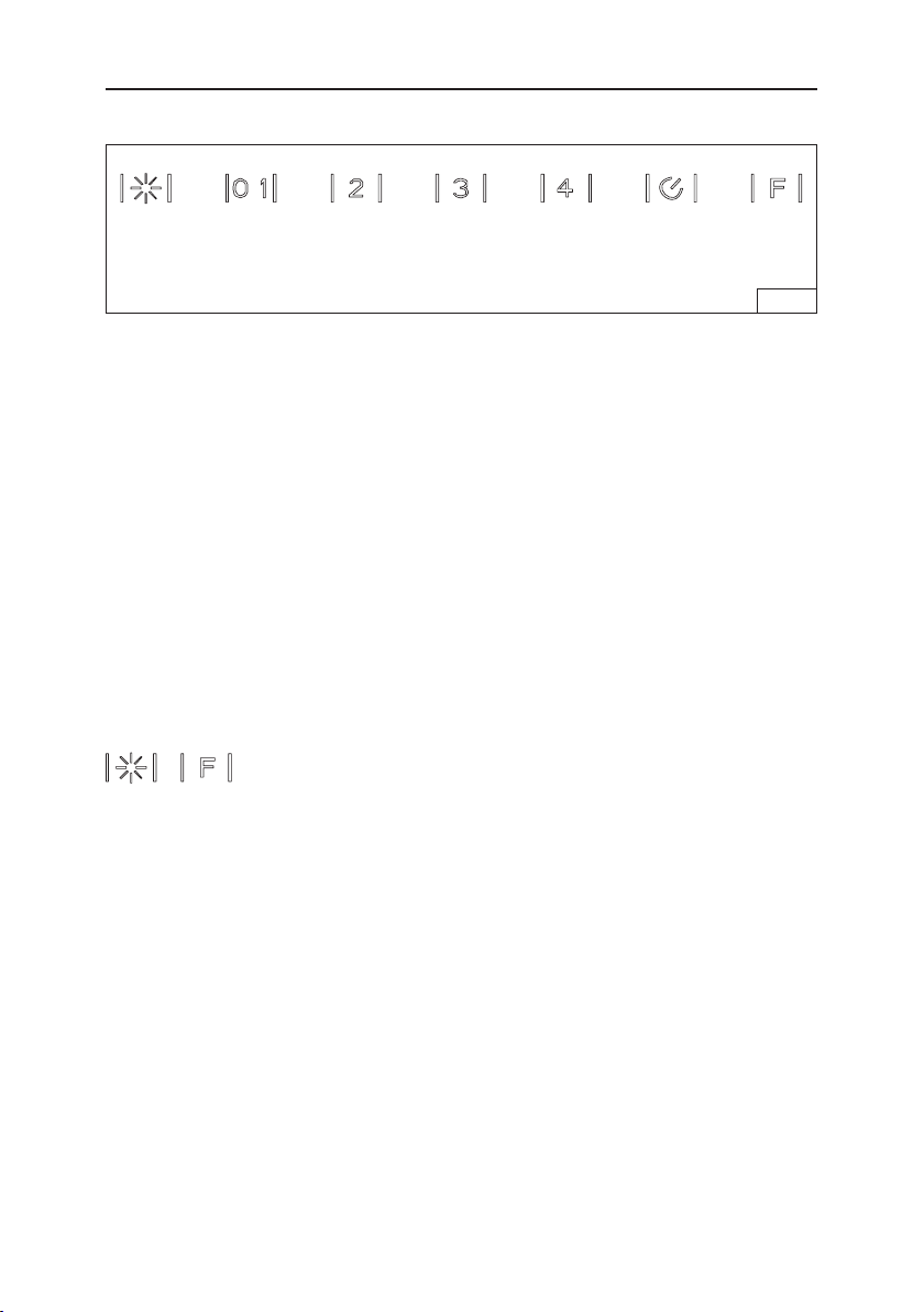
- 50 -
FUNCIONAMIENTO
Controles (Fig. 1)
Termostato HEAT SENTRY™
La campana está equipada con un termostato HEAT SENTRY™. Este termostato es un
dispositivo que encenderá el ventilador o aumentará su velocidad si detecta un calor excesivo
sobre la superficie de cocinado.
1) Si el ventilador está APAGADO: ENCIENDE el ventilador a ALTA velocidad.
2) Si el ventilador está ENCENDIDO a una velocidad menor: pone el ventilador a ALTA velocidad.
Cuando la temperatura disminuye a valores normales, el ventilador regresa a su posición original.
ADVERTENCIA
El termostato HEAT SENTRY puede activar el ventilador aunque la campana esté
APAGADA. Cuando esto ocurre, es imposible APAGAR el ventilador con el interruptor.
Si debe apagar el ventilador, hágalo desde el panel eléctrico principal.
Interruptor
de luz
Encendido/
Apagado
Velocidad
2 del
ventilador
Retardo
temporal
FIG. 1
Velocidad
3 del
ventilador
Velocidad
4 del
ventilador
Reinicio
del filtro
Esta campana está equipada con lo más reciente en tecnología táctil capacitiva. Los botones no se
mueven, sino que son sensibles al tacto. Cuando se capta un contacto, el control emitirá un sonido.
El botón de la luz enciende y apaga las luces LED. Presione una vez para encender las
luces. Presione otra vez para apagar las luces.
El botón Blower On/Off enciende el ventilador en baja velocidad. Presione una segunda vez
para apagarlo.
El botón Blower Speed 2 aumenta la velocidad del ventilador a media-baja.
El botón Blower Speed 3 aumenta la velocidad del ventilador a media-alta.
El botón Blower Speed 4 aumenta la velocidad del ventilador a alta.
El botón Delay activa una función de apagado de retardo. Presione una vez para activar el
retardo de 5 minutos para cualquiera de los ajustes de velocidad del ventilador. Presione
nuevamente para desactivar el retardo.
Filter Reset se ilumina cada 30 horas de funcionamiento, lo cual indica la necesidad de
limpiar los filtros. Después de limpiar o cambiar los filtros, presione una vez para reiniciar el
contador de tiempo de 30 horas.
Modo Clean desactiva los controles para la limpieza de vidrio. Pulse y mantenga pulsado
y
durante 5 segundos. Repita para reactivar los controles.
Función de apagado automático
Si el ventilador y/o las luces están encendidas continuamente 10 horas sin que el usuario
interactúe con los controles, la campana se apagará automáticamente. Presione calquier
botón de control para reactivar la campana.

- 51 -
LÁMPARAS LED
La campana cuenta con lámparas LED que no requieren mantenimiento.
LIMPIEZA Y MANTENIMIENTO
El mantenimiento correcto de la campana de la estufa asegurará el funcionamiento adecuado de la unidad.
Motor
El motor está permanentemente lubricado y nunca necesitará ponerle aceite. Si los cojinetes del
motor están haciendo ruido excesivo o inusual, reemplace el motor con el motor de servicio exacto.
Tambiéndebe reemplazar el impulsor.
Filtro de grasa
El filtro de grasa se debe limpiar con frecuencia, con una solución tibia de detergente y agua.
Elfiltrodegrasa se puede lavar en el lavaplatos.
Limpie los filtros completamente metálicos en el lavaplatos con un detergente sin fosfatos.
El filtrosepuede decolorar si se utilizan detergentes con fosfatos o como resultado de la condición
del agua local, pero esto no afectará el desempeño del filtro. Esta decoloración no está cubierta por
la garantía.
Consulte la sección “INSTALACIÓN DE LOS FILTROS” para ver las instrucciones de instalación
ydesmontaje.
Filtro de recirculación para sistemas sin conductos
El filtro de recirculación para sistemas sin conductos se debe cambiar cada 6 meses. Cámbielo con
más frecuencia si su estilo de cocinar genera más grasa, como al freír y al cocinar en una sartén china
de cuenco redondo. Consulte la sección “INSTALACIÓN DE LOS FILTROS” para ver las instrucciones
de instalación y desmontaje.
Limpieza del acero inoxidable
COSAS QUE PUEDE HACER:
• Regularmente, lave con una tela o trapo limpio
remojado con agua tibia y jabón o detergente
líquido para platos.
• Siempre limpie en la dirección de las líneas
originales de pulido.
• Siempre enjuague bien con agua limpia
(2 o3 veces) después de la limpieza. Séquelo
por completo.
• También puede usar un limpiador casero
especializado para acero inoxidable.
COSAS QUE NO DEBE HACER:
•
Usar lana de acero o acero inoxidable ni algún
otro tipo de raspador para quitar mugre difícil
de sacar.
• Usar limpiadores fuertes ni abrasivos.
• Dejar que se acumule la mugre.
• Dejar que el polvo forme plastas ni que
quede en la campana algún otro residuo de
la construcción. Durante la construcción o
la renovación, cubra la campana para estar
seguro de que el polvo no se pegue a la
superficie de acero inoxidable.
Evite: Al elegir un detergente
• Todo limpiador que contenga blanqueador, pues atacará al acero inoxidable.
• Todo producto que contenga: cloruro, fluoruro, yoduro, bromuro, pues deteriorará las
superficiesrápidamente.
• Todo producto combustible utilizado para la limpieza, como acetona, alcohol, éter, benzol, etc.,
puesson altamente explosivos y nunca se deben usar cerca de una estufa.
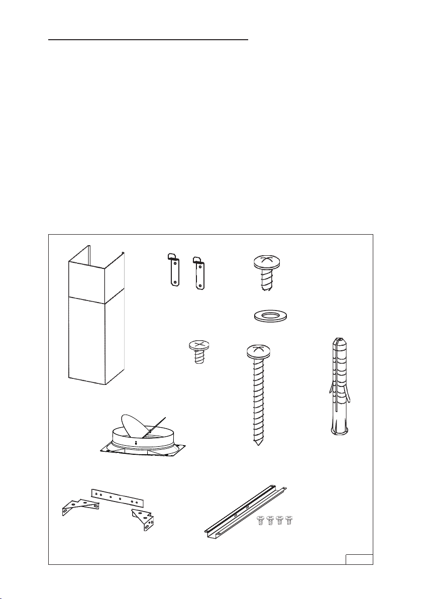
- 52 -
PREPARE LA CAMPANA
Desempaque la campana y revise el contenido del paquete.
Debe contener lo siguiente:
1 - Campana
1 - Conjunto del tubo de humos decorativo
1 - Bolsa de piezas con:
2 - Soportes de montaje
1 - Juego de regulador
1 - Conjunto de soporte de montaje del tubo de humos
8 - Tornillos de montaje (4.8 x 38 mm de cabeza
troncocónica)
4 - Tornillos de montaje (3.9 x 9.5 mm de cabeza
troncocónica)
2 - Tornillos de montaje (3.9 x 6 mm cabeza plana)
8 - Taquetes para placa de yeso
2 - Arandelas planas
1 - Soporte de filtro
4 - Tornillos de montaje (4 x 8 mm)
1 - Instrucciones de instalación
SOPORTES
DE MONTAJE
SOPORTE DE MONTAJE DEL
TUBO DE HUMOS
8 TORNILLOS DE
MONTAJE (4.8 x 38 mm
de cabeza troncocónica)
8 TAQUETES
PARA PLACA
DE YESO
4 TORNILLOS
DE MONTAJE
(3.9 x 9.5 mm
de cabeza
troncocónica)
TUBO DE
HUMOS
DECORATIVO
2 TORNILLOS
DE MONTAJE
(3.9x6mm de
cabeza plana)
FIG. 2
2 ARANDELAS
PLANAS
JUEGO DE
REGULADOR
SOPORTE DE FILTRO
Y (4) TORNILLOS DE
MONTAJE (4 X 8 mm)
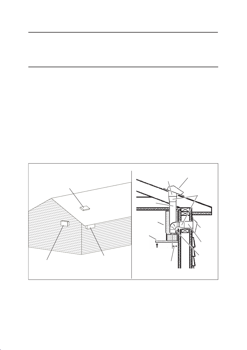
- 53 -
SELECCI
Ó
N DE VENTILADOR EXTERIOR O
EN LÍNEA (WC35E)
PRECAUCIÓN: Con esta campana puede usar un ventilador exterior o en línea.
La campana debe instalarse únicamente con los modelos de ventilador EB6, EB9,
EB12, EB15, ILB3, ILB6, ILB9 o ILB11. No se pueden sustituir otros ventiladores
(los ventiladores se venden por separado).
INSTALACIÓN DEL SISTEMA DE CONDUCTOS
NOTA: Para reducir el riesgo de incendio, use solamente
conductos metálicos.
1.
Elija la ubicación para el montaje del ventilador exterior o en línea.
En las ilustraciones de abajo se muestran sugerencias y restricciones para la
ubicación del montaje.
2.
Un conducto recto y corto permitirá que la campana funcione más
eficientemente.
3.
Los tramos largos de conductos, codos y transiciones reducirán el desempeño
de la campana. Use tan pocos de ellos como sea posible. Es posible que se
requieran conductos más grandes para un mejor funcionamiento con tramos
largos de conductos.
4.
Una vez instalado el ventilador exterior o en línea, conecte el conducto metálico
redondo y trabaje hacia atrás, hacia la ubicación de la campana. Use cinta para
conductos para sellar las uniones entre las secciones de conductos.
5.
Se requiere una transición redonda de 8 a 10 pulg. (20.3 a 25.4 cm) (modelo 414).
Para lograr el mejor rendimiento del aire, instale la transición tan cerca de la
campana como sea posible.
TUBO DE HUMOS
DECORATIVO
CONDUCTO
REDONDO DE
8 PULG. (20.3 CM)
ACEPTABLE
UBICACIONES DE MONTAJE SUGERIDAS
VENTILADOR EXTERIOR
PRECAUCIÓN: PODRÍA NO
CABER DEBAJO DEL ALERO EN
CASAS DE UN SOLO PISO
VENTILADOR
EXTERIOR
CONDUCTO REDONDO
DE 10 PULG. (25.4 CM)
VENTILADOR
EXTERIOR
TRANSICIÓN REDONDA
DE 8 A 10 PULG.
(20.3 A 25.4 CM)
CODO REDONDO
DE 8 PULG.
(20.3 CM)
CONDUCTO
REDONDO
DE 10 PULG.
(25.4 CM)
CAMPANA
DE 24 A 30 PULG.
(61 A 76.2 CM) POR ENCIMA
DE LA SUPERFICIE
DE COCINADO
DISTANCIA DE 4¼ PULG.
(10.8 CM) DE LA LÍNEA
CENTRAL DEL CONDUCTO
A LA PLACA DE YESO
ACEPTABLE
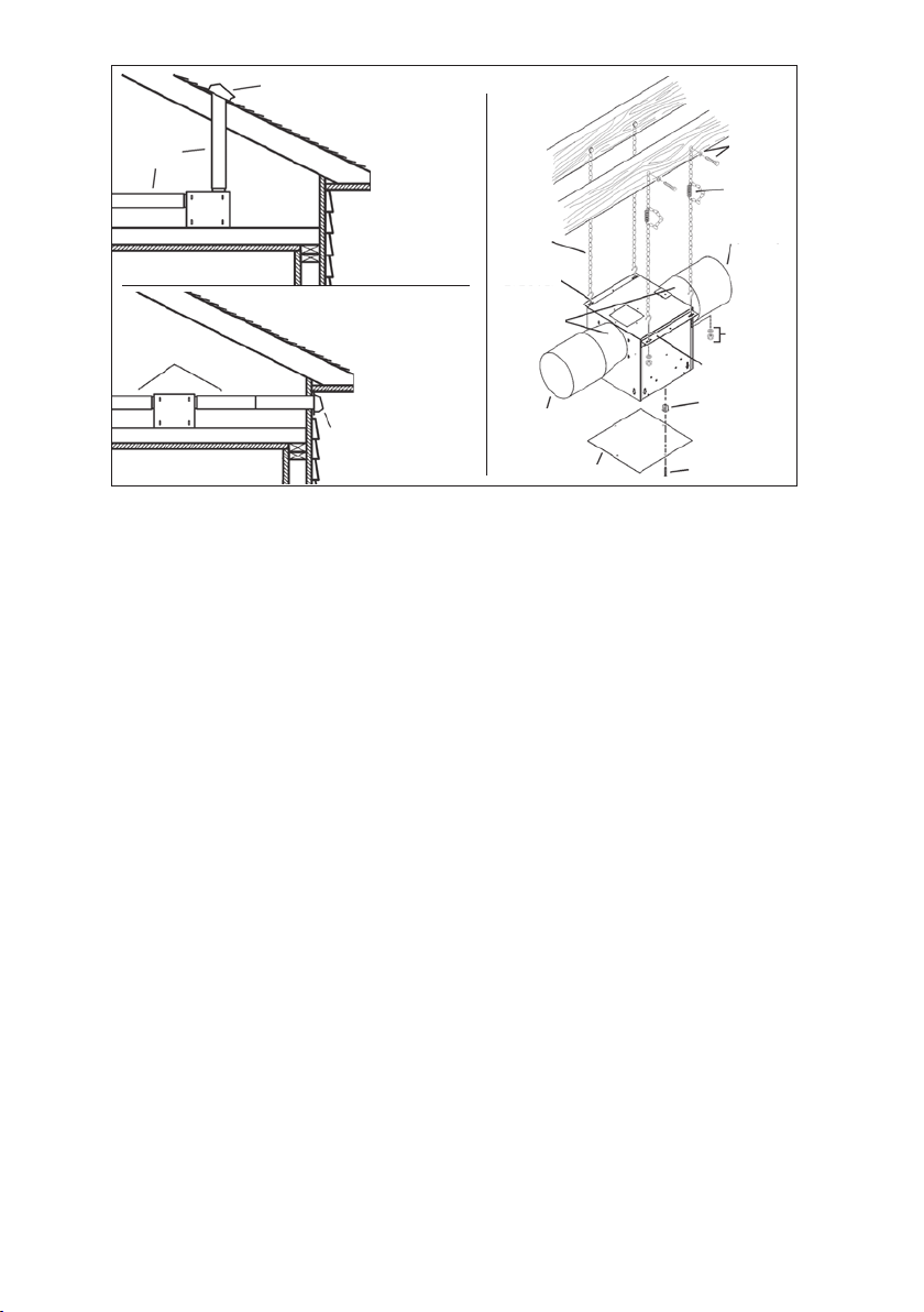
- 54 -
VENTILADOR EN LÍNEA
CONDUCTO
REDONDO
DE 10 PULG.
(25.4 CM)
TAPA DE PARED
TAPA DE PA RED
CONDUCTO
REDONDO
DE 10 PULG.
(25.4 CM)
CADENA DEL
JUEGO DE
SUSPENSIÓN
PERNO DE
ARGOLLA DEL
JUEGO DE
SUSPENSIÓN
TRANSICIÓN
CONDUCTO REDONDO
DE 10 PULG.
(25.4 CM) (SALIDA)
PANEL DE ACCESO
PERNO Y
ARANDELA DEL
JUEGO DE
SUSPENSIÓN
RESORTE DE
EXTENSIÓN
CONDUCTO
REDONDO DE
10 PULG. (25.4 CM)
(ENTRADA)
TUERCA Y
ARANDELA
DEL JUEGO
DE SUSPENSIÓN
SOPORTE DE
MONTAJE
TUERCA DE LA REJILLA
(Instale en los orificios
cuadrados de la cubierta)
TORNILLO DEL PANEL
DE ACCESO
TAPA DE TECHO
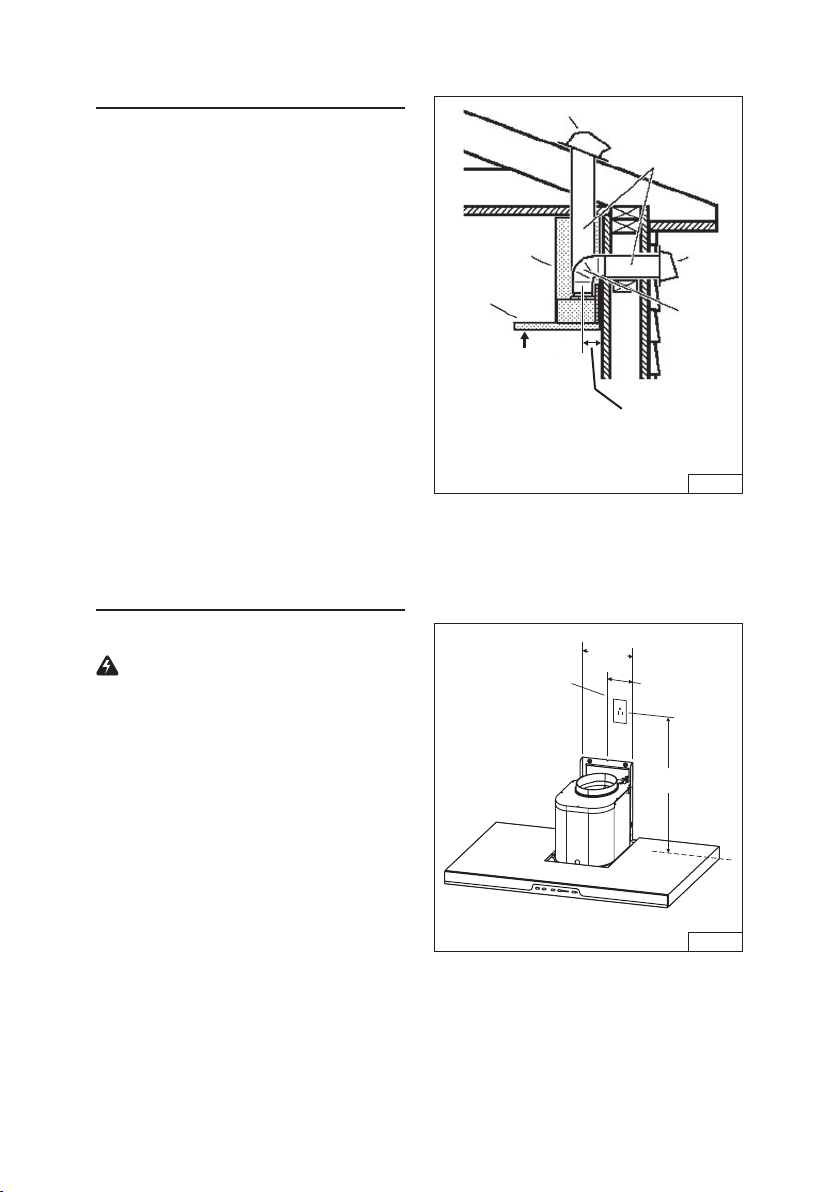
- 55 -
TAPA DE TECHO
CONDUCTO
REDONDO DE
8PULG. (20.3 CM)
TUBO DE
HUMOS
DECORATIVO
CAMPANA
TAPA
DE
PARED
CODO
REDONDO
DE 8 PULG.
(20.3 CM)
DE 24 A 30 PULG.
(61 A 76.2 CM) SOBRE
LA SUPERFICIE DE
COCINADO (Consulte la
sección “INSTALACIÓN
DE LOS SOPORTES DE
MONTAJE” para ver las
limitaciones de montaje)
DISTANCIA DE 4¼ PULG.
(10.8 CM) DE LA
LÍNEA CENTRAL DEL
CONDUCTO A LA PLACA
DE YESO
INSTALACIÓN DEL
SISTEMA DE CONDUCTOS
SOLO CAMPANAS CON CONDUCTOS
PRECAUCIÓN: Para reducir el riesgo
de incendio, use solamente conductos
metálicos.
1. Decida dónde instalará el conducto entre
la campana y el exterior. Fig. 3.
2. Un conducto recto y corto permitirá que
la campana funcione más eficientemente.
3. Los tramos largos de conductos, codos y
transiciones reducirán el rendimiento de
la campana. Use tan pocos de ellos como
sea posible. Es posible que se requieran
conductos más grandes para un mejor
funcionamiento con tramos más largos
de conductos.
4. Instale una tapa de techo o una tapa de
pared. Conecte un conducto metálico
redondo en la tapa y trabaje hacia atrás,
hacia la ubicación de la campana. Use
cinta para conductos para sellar las
uniones entre las secciones de conductos.
INSTALACIÓN ELÉCTRICA
CAMPANAS CON y SIN CONDUCTOS
ADVERTENCIA: Una o más personas
calificadas deben realizar el trabajo de
cableado eléctrico, de acuerdo con todos
los códigos y normas correspondientes.
Esta campana debe estar adecuadamente
conectada a tierra. Interrumpa la energía
eléctrica a la entrada de servicio antes de
comenzar el cableado.
1. Planifique la ubicación de la campana
sobre la superficie de la estufa. Consulte la
sección “INSTALACIÓN DEL SOPORTE
DE MONTAJE” para ver las opciones de la
altura de montaje de la campana.
2. Instale una caja estándar de tomacorriente
de pared de 2 x 4 pulg. (5.1 x 10.2 cm) y un
receptáculo de 3 hojas de 125 V y 15 A con
conexión a tierra. Fig. 5.
3. Monte el centro del tomacorriente de pared
de 18½ a 19½ pulg. (47 a 49.5 cm) por
encima de la parte inferior de la campana.
4. Ubique la caja y el receptáculo dentro de los
límites mostrados y fuera de la línea central
de los conductos (a fin de dejar espacio
para el enchufe del cable de alimentación
y el tubo de humos).
FIG. 4
18½ a 19½ pulg.
(47 a 49.5 cm)
4 pulg.
(10.2 cm)
8 pulg.
(20.3 cm)
LÍNEA CENTRAL
DE LA CAMPANA
FIG. 3
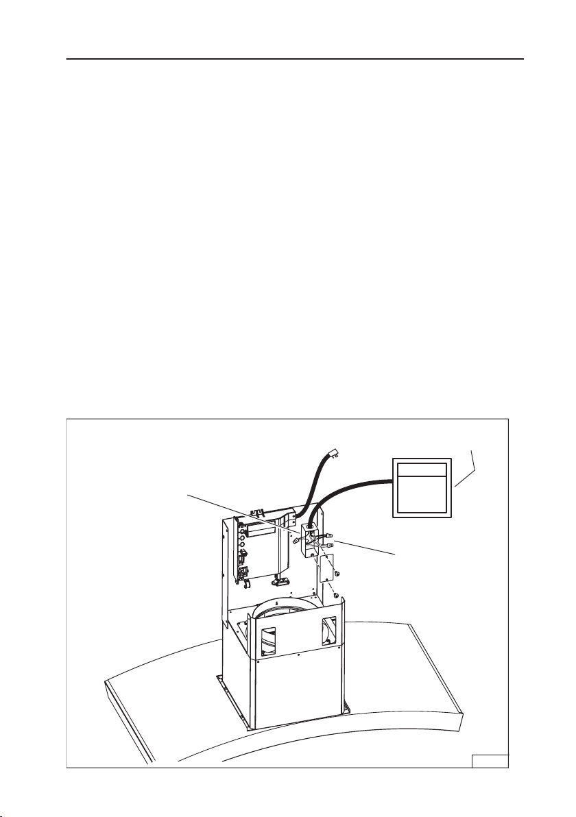
- 56 -
FIG. 5
CONEXIONES EL
É
CTRICAS DEL VENTILADOR EXTERNO
Conexión del ventilador en la campana:
1.
Tienda un cable eléctrico de dos hilos y conexión a tierra desde el ventilador
exterior o en línea hasta la caja de cableado marcada como “motor connection”
(“conexión del motor”).
2.
Quite la cubierta de la caja de cableado y retire un agujero ciego.
3. Haga pasar 6 pulg. (15.2 cm) de cable a través de la abertura ciega y asegure el
cable a la caja de conexiones con un conector apropiado.
4.
Haga las conexiones eléctricas en la campana. Conecte blanco con blanco,
rojo con negro y verde con tierra.
5.
Vuelva a colocar la cubierta de la caja de conexiones y los tornillos.
Asegúrese de que los cables no queden atrapados entre la cubierta y la caja.
Conexión del ventilador exterior o en línea:
1.
Haga las conexiones eléctricas en el ventilador exterior o en línea
(consulte las instrucciones incluidas con el ventilador).
Conexión de energía eléctrica en la campana:
1.
Enchufe el cordón eléctrico en el receptáculo eléctrico de la pared.
CONEXIÓN DEL VENTILADOR EN LA CAMPANA
CAJA MARCADA COMO
“MOTOR CONNECTION”
CONECTAR: BLANCO
CON BLANCO,
ROJO CON NEGRO,
VERDE CON TIERRA.
Ventilador
exterior o en línea
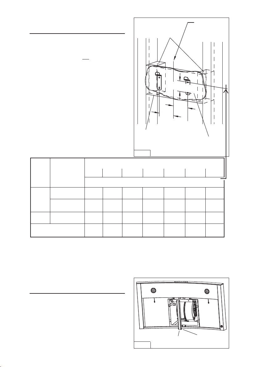
- 57 -
INSTALACIÓN DE LOS
SOPORTES DE MONTAJE
CAMPANAS CON y SIN CONDUCTOS
1. Construya un bastidor de madera en la
pared que quede al ras de la superficie
interior de los montantes de pared. Fig. 6.
Asegúrese de que:
a) El bastidor esté centrado en el lugar
de la instalación.
b) La altura del bastidor permita fijar los
soportes de montaje en el bastidor
dentro de las dimensiones mostradas.
2. Después de terminar la superficie
de la pared, asegure los soportes de
montaje a la estructura con (4) tornillos de
montaje de 4.8 x 38 mm. Vea la ubicación
del soporte de montaje en la tabla que
aparece abajo.
Notas:
a. La distancia mínima de la campana sobre la superficie de la estufa no debe ser menor de 24 pulg.
(61 cm). Se recomienda enfáticamente una distancia máxima de 30 pulg. (76.2 cm) sobre la superficie de la
estufa para la mejor captura de las impurezas resultantes del cocinado. Las distancias mayores de 30pulg.
(76.2 cm) se dejan a criterio de la persona que hace la instalación y del usuario, y si la altura del cielo raso
y la longitud del tubo de humos lo permiten.
b. Requiere una extensión opcional del tubo de humos de 10 pies (305 cm), el modelo con conductos
AEWC345IQSB o el modelo sin conductos AEWC345IQSBN.
DISTANCIA MAYOR DE 36 PULG. (91 CM) DE LA CAMPANA A LA SUPERFICIE DE LA
ESTUFA (vea la nota a continuación)
ALTURA
DELCIELO
RASO
8 PIES
(244 CM)
37-7/8 pulg.
(96.2 cm)
38-7/8 pulg.
(98.7 cm)
39-7/8 pulg.
(101.3 cm)
40-7/8 pulg.
(103.8 cm)
9 PIES
(274 CM)
41-7/8 pulg.
(106.4 cm)
42-7/8 pulg.
(108.9 cm)
43-7/8 pulg.
(111.4 cm)
CON CONDUCTOS
SIN CONDUCTOS
CON O SIN
CONDUCTO
CONFIGURACIÓN
37-7/8 pulg.
(96.2 cm)
38-7/8 pulg.
(98.7 cm)
39-7/8 pulg.
(101.3 cm)
40-7/8 pulg.
(103.8 cm)
40-7/8 pulg.
(103.8 cm)
41-7/8 pulg.
(106.4 cm)
42-7/8 pulg.
(108.9 cm)
43-7/8 pulg.
(111.4 cm)
10 PIES (305 CM)
(vea la nota b)
39-7/8 pulg.
(101.3 cm)
40-7/8 pulg.
(103.8 cm)
41-7/8 pulg.
(106.4 cm)
42-7/8 pulg.
(108.9 cm)
43-7/8 pulg.
(111.4 cm)
37-7/8 pulg.
(96.2 cm)
38-7/8 pulg.
(98.7 cm)
INSTALE EL SOPORTE
CENTRAL
1. Instale el soporte central usando (4)
tornillos M4x8. Fig. 7.
FIG. 7
(4)
TORNILLOS
M4x8
SOPORTE
CENTRAL
41-7/8 pulg.
(106.4 cm)
42-7/8 pulg.
(108.9 cm)
43-7/8 pulg.
(111.4 cm)
SOPORTE
TRANSVERSAL DE
MADERA DETRÁS DE
LA PLACA DE YESO
PLACA DE YESO
FIG. 6
BASTIDOR DETRÁS
DE UN SOPORTE
TRANSVERSAL DE
MADERA
LÍNEA CENTRAL
3-1/2 pulg.
(8.9 cm)
3-1/2 pulg.
(8.9 cm)
2-3/16 pulg.
(5.6 cm)
30 pulg.
(76.2 cm)
24 pulg.
(61 cm)
25 pulg.
(63.5 cm)
26 pulg.
(66 cm)
27 pulg.
(68.6 cm)
28 pulg.
(71.1 cm)
29 pulg.
(73.7 cm)
UBICACIÓN DEL ORIFICIO CENTRAL DEL SOPORTE DE MONTAJE POR ENCIMA DE
36 PULG. (91 CM) SOBRE LA SUPERFICIE DE LA ESTUFA
---
---
---

- 58 -
INSTALACIÓN DEL
SOPORTE DE MONTAJE
DEL TUBODEHUMOS
CAMPANAS CON Y SIN CONDUCTOS
1. Monte el soporte de montaje del tubo de humos,
ajustando el ancho exterior como se muestra.
Fig. 8.
2. Centre cuidadosamente el soporte de montaje
directamente sobre la ubicación de la campana
de la estufa.
3. Fije el conjunto del soporte en el cielo raso
usando (2) tornillos de montaje de 4.8x38mm
y taquetes para placa de yeso. Fig. 9.
Asegúrese de que el soporte quede presionado
sobre la esquina, pegado contra la pared y
centrado sobre la campana.
SOPORTE DE MONTAJE DEL TUBO DE HUMOS
11¾ pulg.
(29.8 cm)
FIG. 8
TORNILLOS DE MONTAJE DE
CABEZA PLANA DE 3.9 x 6 mm
FIG. 9
TORNILLOS DE MONTAJE
DE 4.8 X 38 mm
TAQUETES PARA PLACA DE YESO
FIG. 11
INSTALACIÓN DE LA
CAMPANA
Nota: Antes de realizar la instalación final, retire la
película protectora de plástico de todas las superficies
exteriores, tubos de humos decorativos y filtros.
Quite los filtros. (Consulte la sección “Instalación
de los filtros”.)
INSTALACIÓN CON CONDUCTOS y SIN CONDUCTOS
1. Retire la caja del sistema eléctrico del bastidor de
la chimenea quitando (2) tornillos de 3.9 x 9.5 mm.
Fig. 10.
2. Fije la caja del sistema eléctrico al bastidor usando
(2) tornillos de 3.9 x 9.5 mm que quitó en el Paso
1y (2) tornillos de 3.9 x 9.5 mm y (2) arandelas
planas de la bolsa de herrajes.
3. Instale la campana en los soportes de montaje de
pared. Fig. 11. Ajuste los tornillos de nivelación en
los soportes de montaje para nivelar la campana
conelpiso.
4. Marque e instale (2) tornillos adicionales, talcomo
se ilustra. Use taquetes para panel de yeso
solamente si fuera necesario.
CAJA DEL
SISTEMA
ELÉCTRICO
FIG. 10
RETIRE (2)
TORNILLOS DE
3.9 x 9.5 mm
TORNILLOS DE
4.8 X 38 mm
INSTALE (4)
TORNILLOS DE
3.9 x 9.5 mm
Y ARANDELAS
PLANAS SOBRE
(2) TORNILLOS

- 59 -
FIG.12
CONDUCTO
METÁLICO CON
DIÁMETRO DE
8PULG. (20.3 CM)
ÚNICAMENTE EN INSTALACIONES CON
CONDUCTOS
Nota: Las habitaciones con cielo raso de
10pies (305 cm) requieren la extensión del
tubo de humos modelo AEWC345IQSB,
disponible en la concesionaria de su
localidad. Deseche el tubo de humos
superior (incluido con la campana) y
reemplácelo con la extensión de tubo de
humos más larga.
1.
Retire la cinta protectora de la salida del
ventilador antes de instalar el regulador a
la campana con (4) tornillos suministrados
y aplique cinta para conductos de aluminio
a las uniones. Fig. 12.
2. Tienda un conducto metálico de 8pulg.
(20.3 cm) de diámetro hasta elsitioexterior.
3. I
nstale una tapa para pared o techo apropiada,
con el regulador de tiro, paraextraer el aire
hacia el exterior.
4. Una todas las uniones con cinta de aluminio
para conductos.
5. Conecte el cable eléctrico en el tomacorriente.
Fig. 13.
6. Instale los tubos de humos decorativos superior
e inferior en la campana.
- Las rejillas de ventilación quedan
ocultas en techos de 8 pies (244 cm)
- Las rejillas de ventilación quedan
expuestas en techos de 9 pies (274 cm)
7. Asegure el tubo de humos superior al
soporte de montaje del tubo con (2)tornillos
de 3.9 x 6 mm. Fig. 14.
FIG.13
FIG.14
CONECTOR DEL
REGULADOR
DE TIRO/
CONDUCTO
REJILLAS DE
VENTILACIÓN
OCULTAS
TECHO
TORNILLOS
DE
3.9 X 6 mm
2

- 60 -
ÚNICAMENTE EN INSTALACIONES
SINCONDUCTOS
Nota:
a. Compre un juego de recirculación sin
conductos, modelo ANKWC345.
b. Las habitaciones con cielo raso de 10pies
(305 cm) requieren la extensión del tubo
de humos modelo AEWC345IQSBN,
disponible en la concesionaria de su
localidad. Deseche el tubo de humos
superior (incluido con la campana) y
reemplácelo con la extensión de tubo de
humos más larga.
1. Instale el collarín de descarga
suministrado con la campana. Fig. 15.
2. Fije el adaptador de 6 a 8 pulg. (15.2 a
20.3 cm) a la descarga del ventilador y
aplique cinta para conductos de aluminio
a las uniones. Fig. 15.
3. Instale el pleno a la parte superior del tubo
de humos decorativo usando (4) tornillos
de 3.4 x 15 mm suministrados, como se
ilustra. Fig. 16.
4. Fije un conducto expansible de 6 pulg.
(15.2 cm) al pleno y aplique cinta para
conductos de aluminio a las uniones.
Fig.17.
5. Fije el bastidor para filtro sin conductos
usando (4) tornillos de 3.9 x 6 mm.
Fig. 18.
FIG.15
FIG.16
FIG.17
TORNILLOS DE
3.9 X 6 mm
FIG.18

- 61 -
6. Asegure juntos temporalmente el tubo de
humos superior e inferior con cinta para
conductos, como se muestra. Fig. 19.
7. Levante el tubo de humos en su posición
por arriba de la campana. Asegure el tubo
de humos superior al soporte de montaje
del tubo con (2) tornillos de 3.9 x 6 mm.
Fig. 20.
8. Estire el conducto expansible, conécteloal
adaptador de 6 a 8 pulg. (15.2 a 20.3 cm)
y aplique cinta para conductos en las
uniones. Fig. 21.
9. Conecte el cable eléctrico en el tomacorriente.
10. Quite la cinta de los tubos de humos y baje
en posición sobre la campana. Fig. 22.
FIG.20
FIG.19
FIG.21 FIG.22
TORNILLOS DE
3.9 X 6 mm
2

- 62 -
INSTALACIÓN DE FILTROS
CAMPANAS CON Y SIN CONDUCTOS
1. Para quitar el filtro de GRASA, estire hacia
abajo la lengüeta de cierre para desacoplar
el filtro de la campana. Incline el filtro hacia
abajo y quítelo. Fig.23.
2. Para instalar el filtro de GRASA, alinee
las lengüetas posteriores del filtro con las
ranuras de la campana. Estire hacia abajo
la lengüeta del cierre, presione el filtro en
su posición y libere. Asegúrese de que el
filtro esté firmemente acoplado después
de su instalación. Fig. 24.
NOTA: Antes de utilizar este producto,
despegue la película protectora del bastidor
del filtro.
SOLO CAMPANAS PARA SISTEMAS SIN
CONDUCTO
1. Para quitar el filtro de CARBÓN, sujete y
empuje la pestaña del filtro hacia la parte
de atrás de la campana. Estire el filtro
hacia abajo para desacoplar las pestañas
posteriores del filtro. Fig. 23.
2. Para instalar el filtro de CARBÓN, alinee
el filtro en la abertura rectangular. Empuje
el filtro contra los resortes en la parte
posterior de la campana y presione en
su lugar. Asegúrese de que el filtro esté
firmemente instalado después de la
instalación.
3. Instale el filtro de GRASA después de
haber instalado el filtro de carbón.
FIG.23
FIG.24
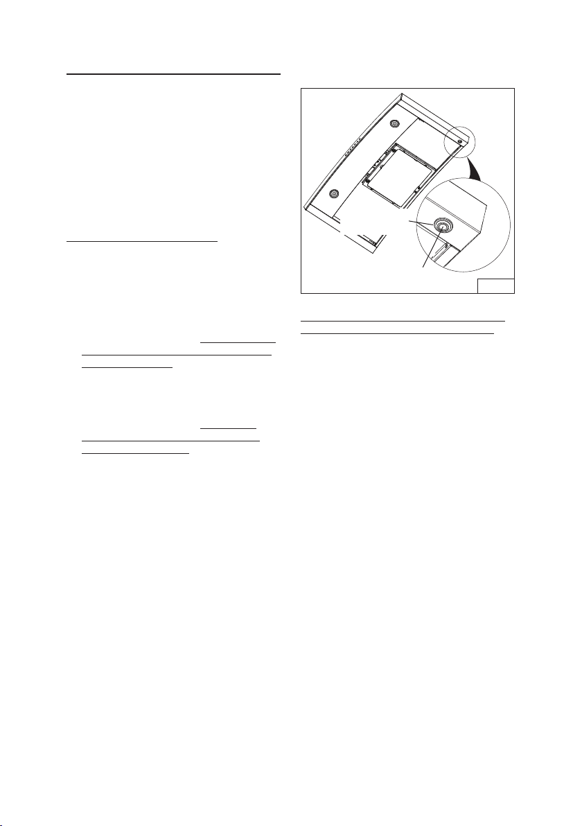
- 63 -
CALIBRACIÓN DEL
VENTILADOR IQ™
SOLO UNIDADES CON CONDUCTOS DE
VENTILADOR INTERNO
Después de instalar y cablear la campana,
active el proceso de calibración
(nuestratecnología de sistema de
desempeño garantizado, para asegurar que
se suministre el flujo de aire nominaltotal).
Antes de la calibración, asegúrese de
que todos los filtros, bombillas de luz y el
sistema de conductos estén instalados.
PROCESO DE CALIBRACIÓN Fig. 21.
Sostenga el botón de calibración
3segundos; el botón se encenderá y estará
así hasta por 13 minutos. El ventilador
arrancará y comenzará el proceso
de calibración. Cuando se termine la
calibración, ocurriráuna de dos cosas:
1. El ventilador se apaga y la luz del botón
de calibración permanece encendida =
Calibración exitosa. Presione el botón
para apagar la luz LED. Nota: La luz LED
también se apagará si selecciona alguna
velocidad del ventilador en el control.
2. El ventilador se apaga y el botón de
calibración destella continuamente =
Demasiada restricción en los conductos
impide que el ventilador IQ™ obtenga
el flujo de aire nominal. El ventilador
se configura automáticamente en su
intensidad máxima.
NOTA: Elementos comunes que provocan
restricciones: el alerón del regulador
está restringido (regulador decontratiro,
tapadepared, tapa de techo), demasiados
codos, tamaño de conducto menor del
80% de salida de la campana, mala
transición, uso de conductos flexibles
y/oconductosaplastados.
FIG.25
BOTÓN DE
CALIBRACIÓN
LUZ DE
CALIBRACIÓN
Hay disponibles tres opciones si el sistema
de campana tiene demasiada restricción:
1. Aceptar el flujo de aire como está.
a. Presione el botón de calibración para
aceptar el flujo de aire tal cual. El
ventilador IQ™ está configurado ahora
en el rendimiento más alto posible. La
luz de calibración destellante se apaga.
Nota: La luz LED también se apagará
si selecciona alguna velocidad del
ventilador en el control.
2. Corrija la restricción del conducto, despeje
los datos de calibración originales y repita
el proceso de calibración.
a. Corrija la restricción del conducto.
b. Despeje los datos de calibración
originales manteniendo presionado
el botón de calibración durante 10
segundos. La luz destellará 3 veces
para confirmar y la configuración del
ventilador regresará a los ajustes
predeterminados.
c. Repita el proceso de calibración desde
el principio.
3. Despeje los datos de calibración para
reiniciar la campana a la configuración de
fábrica y obtener un rendimiento estándar
de alta presión del ventilador.
a. Despeje los datos de calibración y
reinicie la campana a los ajustes
predeterminados de fábrica
manteniendo presionado el botón de
calibración durante 10 segundos. La luz
destellará 3 veces para confirmar y la
configuración del ventilador regresará a
los ajustes predeterminados.
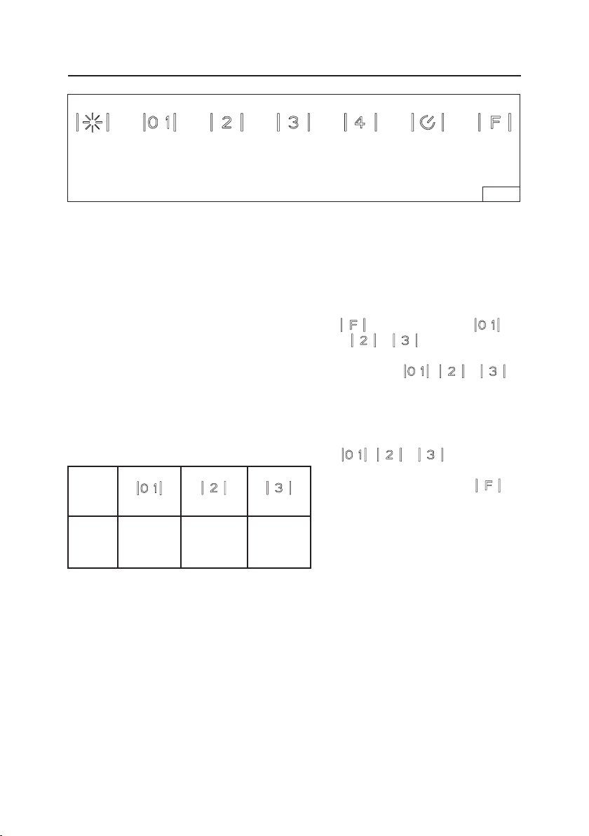
- 64 -
La campana está diseñada para funcionar
con diversos modelos diferentes de
ventilador. Antes de usarlo, primero debe
programar el control según su modelo de
ventilador, con el fin de obtener velocidades
de operación adecuadas.
Del cuadro siguiente:
1. Encuentre el número de
CONFIGURACIÓN que corresponde al
modelo de ventilador instalado con su
campana.
2. El control está preconfigurado de
fábrica en la CONFIGURACIÓN 3.
Sisumodelo de ventilador se encuentra
en CONFIGURACIÓN 3, no se requiere
programación y la campana está lista
para usarse.
CONFIGURACIÓN CONFIGURACIÓN CONFIGURACIÓN
(predeterminada)
VENTILADOR
MODELO
NÚMERO
EB6
ILB3
ILB6
EB12
EB15
ILB9
EB9
ILB11
3. Para programar modelos de ventilador
enumerados en CONFIGURACIÓN 1 y 2:
A) La campana debe tener suministro
eléctrico. El ventilador y las luces
deben estar apagadas.
B) Presione y mantenga presionado
durante 5 segundos.
+
+
destellará 3
veces. Después de 1 segundo, se
encenderán , o
para indicar el ajuste actual.
C) Seleccione la CONFIGURACIÓN
adecuada para su ventilador en
el cuadro a la izquierda. Presione
, o para
seleccionar la CONFIGURACIÓN
adecuada. Luego presione
para confirmar y guardar el
nuevoajuste.
D) La campana está ahora lista para usar.
PROCEDIMIENTO DEL MODO DE PROGRAMACIÓN DEL
VENTILADOR EXTERNO (WC35E)
Interruptor
de luz
Encendido/
Apagado
Velocidad
2 del
ventilador
Retardo
temporal
FIG. 26
Velocidad
3 del
ventilador
Velocidad
4 del
ventilador
Reinicio
del filtro
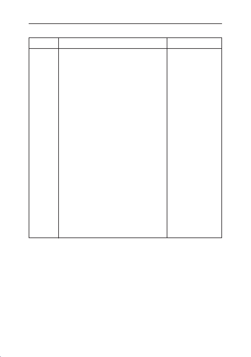
- 65 -
PIEZAS DE SERVICIO
SERIE WC35IQ
CLAVE N.º DESCRIPCIÓN N.º DE PIEZA
CAS CONJUNTO DE VENTILADOR 06002259
49 VENTILADOR (EN SENTIDO
DE LAS AGUJAS DEL RELOJ) 03295071
IME CONJUNTO DE INSTALACIÓN ELÉCTRICA 06145222
114 ABRAZADERA DE ALAMBRE 032904990
506 CONTROLADOR BLDC 97019431
67 CABLES 06102592
202 TOPE DEL REFLECTOR 03292290
415 GUÍA DE CABLE 03202288
60 CABLE DE ALIMENTACIÓN 02300249
415 GUÍA DE CABLE 03202288
37 PERILLA 02300804
474 LÁMPARA LED 08093413
AQI CONJUNTO DE LA CAJA DEL INTERRUPTOR 06102590
439 ANILLO DE TOPE 02320034
507 BOTÓN DE CALIBRACIÓN DE CONJUNTO 06102584
195 SOPORTE E3351078
9 FILTRO DE GRASA 08087823
ARU JUEGO DE SALIDA DE AIRE DE CONEXIÓN 080810849
485 JUEGO DE CONDUCTO TELESCÓPICO 08016368
120 SOPORTE DE MONTAJE DEL TUBO DE HUMOS 08091851
195 SOPORTE CENTRAL E3351078
122 PLENO PARA SISTEMAS SIN CONDUCTOS 08093478
86 ANILLO ADAPTADOR DE 6 PULG. (15.2 CM) 032292300
503 CONDUCTO EXPANSIBLE DE 6 PULG. (15.2 CM) 02011557
58 REDUCTOR DE 8 A 6 PULG. (20.3 CM A 15.2 CM) 03294170
FILTRO NO CONDUCTO 08999176
BOLSA DE ACCESORIOS 080810993

- 66 -
PIEZAS DE SERVICIO
SERIE WC35IQ
474
485
64
US-DUNE HS BLDC
195
CAS
IME
506
202
60
202
415
(03202288)
415
(03202288)
49
114
AQI
9
120
503
86
122
67
ARU
439
37
507
58
- 67 -
PIEZAS DE SERVICIO
SERIE WC35E
CLAVE N.º DESCRIPCIÓN N.º DE PIEZA
IME CONJUNTO DE INSTALACIÓN ELÉCTRICA 06145223
166 TABLERO DE CIRCUITOS ELÉCTRICOS IMPRESOS 08080877
145 CAJA DE CONEXIÓN DEL CABLE DE ALIMENTACIÓN 032920170
147 PINZA DE UNIÓN R2300132
146 CUBIERTA DE LA CAJA DE CONEXIÓN DEL CABLE
DE ALIMENTACIÓN 03292180
151 TOPE DE CABLES DE LA CAJA ELÉCTRICA 032920200
114 ABRAZADERA DE ALAMBRE 032904990
67 CABLES 06102593
60 CABLE DE ALIMENTACIÓN 02300249
37 PERILLA 02300804
474 LÁMPARA LED 08093413
AQI CONJUNTO DE LA CAJA DEL INTERRUPTOR 06102591
195 SOPORTE E3351078
9 FILTRO DE GRASA 08087823
ARU JUEGO DE SALIDA DE AIRE DE CONEXIÓN 080810849
485 JUEGO DE CONDUCTO TELESCÓPICO 08016368
120 SOPORTE DE MONTAJE DEL TUBO DE HUMOS 08091851
195 SOPORTE CENTRAL E3351078
BOLSA DE ACCESORIOS 080810993

- 68 -
PIEZAS DE SERVICIO
SERIE WC35E
US-DUNE HS EXT BLDC
474
195
AQI
9
37
485
IME
120
67
ARU
116
115
415
202
60
114

- 69 -
99045142C
GARANTÍA
GARANTÍA LIMITADA DE UN AÑO PARA LOS PRODUCTOS BEST
Broan-NuTone LLC (Broan-NuTone) garantiza al consumidor comprador original de los productos BEST que tales
productos estarán libres de defectos en materiales o mano de obra durante un período de un año a partir de la fecha
de la compra original. NO EXISTEN OTRAS GARANTÍAS, EXPRESAS NI IMPLÍCITAS, INCLUIDAS, ENTRE OTRAS,
GARANTÍAS IMPLÍCITAS DE COMERCIALIZACIÓN O IDONEIDAD PARA UN PROPÓSITO PARTICULAR.
Durante este período de un año, Broan-NuTone, a su criterio, reparará o reemplazará sin cargo alguno cualquier pieza
o producto que se encuentre defectuoso bajo condiciones normales de uso y servicio.
LA PRESENTE GARANTÍA NO CUBRE ARRANCADORES DE LÁMPARAS FLUORESCENTES, TUBOS, BOMBILLAS
HALÓGENAS E INCANDESCENTES, FUSIBLES, FILTROS, CONDUCTOS, TAPAS DE TECHO O DE PARED Y
DEMÁS ACCESORIOS DE CANALIZACIÓN. Esta garantía no cubre (a) mantenimiento y servicio normales, ni (b)
ningún producto o piezas que se hayan sometido a uso inadecuado, negligencia, accidente, mantenimiento o reparación
inadecuada (nohecha por Broan-NuTone), instalación incorrecta o instalación en contra de las instrucciones de
instalación recomendadas.
La duración de cualquier garantía implícita se limita a un período de un año, como se especifica en la garantía expresa.
Algunos estados no permiten limitaciones en cuanto al tiempo de vencimiento de una garantía implícita, por lo que la
limitación antes mencionada podría no aplicarse a usted.
LA OBLIGACIÓN DE BROAN-NUTONE DE REPARAR O REEMPLAZAR, A CRITERIO DE BROAN-NUTONE,
SERÁ EL ÚNICO Y EXCLUSIVO RECURSO DEL COMPRADOR BAJO ESTA GARANTÍA. BROAN-NUTONE NO
SERÁ RESPONSABLE POR DAÑOS INCIDENTALES, RESULTANTES O ESPECIALES QUE SURJAN DEL USO
O DESEMPEÑO DEL PRODUCTO O EN RELACIÓN CON EL MISMO. Algunos estados no permiten la exclusión o
limitación de daños incidentales o resultantes, por lo que la limitación antes mencionada podría no aplicarse a usted.
Esta garantía le otorga derechos legales específicos, y usted podría tener otros derechos que varían de un estado a
otro. Esta garantía sustituye a todas las garantías anteriores.
Para tener derecho al servicio de la garantía, usted debe (a) notificar a Broan-NuTone a la dirección y número de teléfono
que aparecen abajo, (b) proporcionar el número de modelo y la identificación de la pieza y (c) describir la naturaleza de
cualquier defecto en el producto o pieza. En el momento de solicitar el servicio cubierto por la garantía, debe presentar
un comprobante de la fecha de compra original.
En EE.UU. - Best®, 926 W. State Street, Hartford, WI 53027 (800-558-1711)
En Canadá - Best®, 550 Lemire Blvd., Drummondville, QC J2C 7W9 (866-737-7770)
www.BestRangeHoods.com

- 70 -

- 71 -

- 72 -
99045142C
