SA405
INSTRUCTION MANUAL
If you have any questions along the way, just give us a call:
1-800-359-5520 We’re ready to help!
We’ll Make It Stress-Free
2
Please verify the following items:
Your TV, soundbar, soundbar mount, and any accessories you
plan to install DO NOT EXCEED the specifi ed weight limit of
your TV wall mount.
You read and understand these directions.
You refer to the documentation that came with your sound bar,
your TV and your TV wall mount for additional guidance.
You have the tools needed for installation.
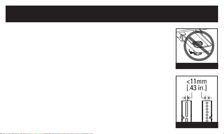
You CAN NOT use this product if your TV mount’s interface bracket:
includes built-in/integrated spacers (see Figure 1), or
the mounting holes/slots are greater than 11mm [.43 in.] (see Figure 2).
IMPORTANT SAFETY INSTRUCTIONS
PLEASE READ ENTIRE MANUAL PRIOR TO USE – SAVE THESE INSTRUCTIONS
Before You Begin
Figure 2
Figure 1
3
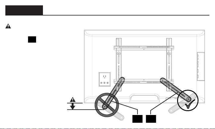
WARNING:
• This soundbar mount is only designed for use with TV wall mounts that meet third party
safety certifi cations.
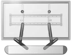
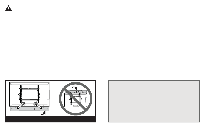
• This soundbar mount is ONLY designed to mount BELOW the television (see Figure 3).
• This soundbar mount is designed to be installed and utilized only as specifi ed in this manual.
The manufacturer is not responsible for improper assembly, use, or handling of this product.
• Your wall must be capable of supporting fi ve times the weight of your TV, TV mount, and
soundbar combined.
• Failure to follow these instructions could result in an unstable situation that may result
in property damage or personal injury.
TV
Soundbar
Figure 3
If you have any questions,
please contact
Customer Service:
1-800-359-5520
4
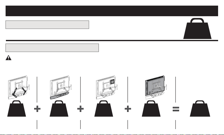
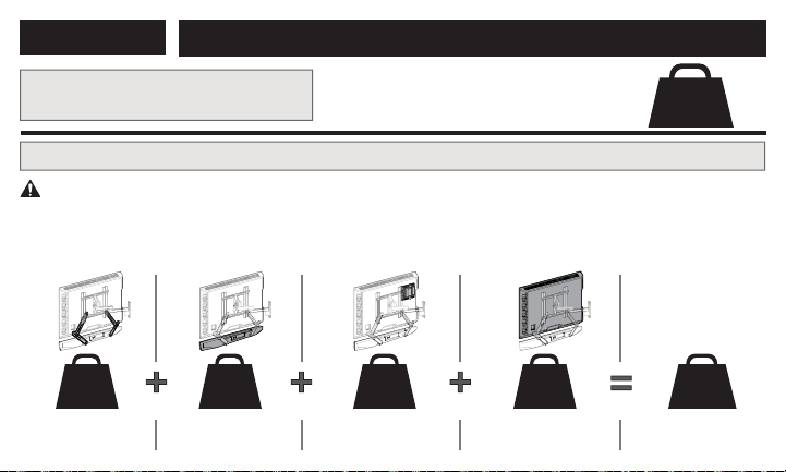
Weight Restrictions
Weight Limit for SA405
Weight Limit for Your TV Mount
DO NOT EXCEED 15 lbs. (6.8 kg)
for this Soundbar Mount
15 lbs.
(6.8 kg)
CAUTION: Avoid potential personal injuries and property damage!
The weight of your TV, PLUS this soundbar mount, your soundbar, and any accessories, MUST BE LOWER
than the maximum weight rating of your TV mount. See your TV mount's manual for maximum weight allowed.
2 lbs.
(0.9 kg)
__ kg
(__ lbs.)
__ kg
(__ lbs.)
__ kg
(__ lbs.)
(plus) (plus) (plus)
(equals)
Soundbar
Mount
ANY Other
Accessories
Your
Soundbar
Your TV
TOTAL
WEIGHT
Maximum for
Your TV Mount
5
3
rd
Party Certifi ed
TV Wall Mount *
*Your TV wall mount may vary from the
illustrations throughout this manual —
note that the procedure to install the
soundbar is the same.
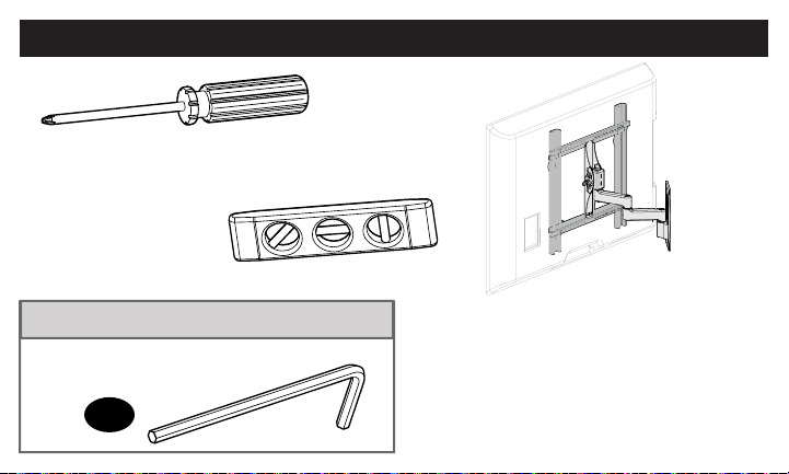
Items Needed
Included in this Kit
H
Phillips Screwdriver
Level
3/16 in. Hex Key
6
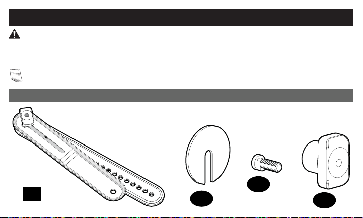
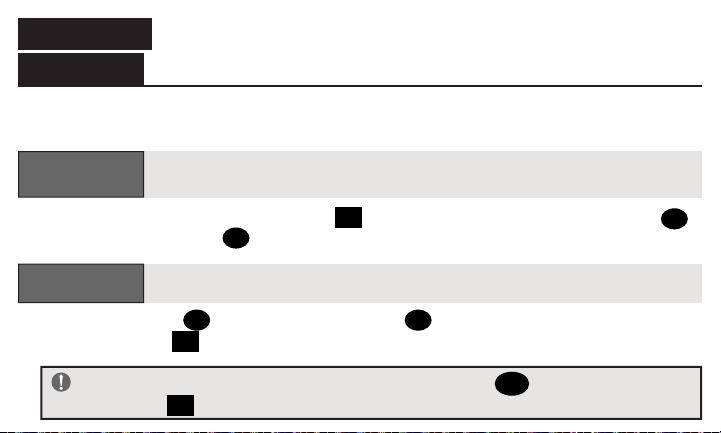
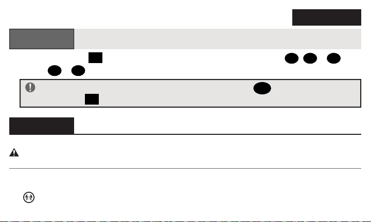
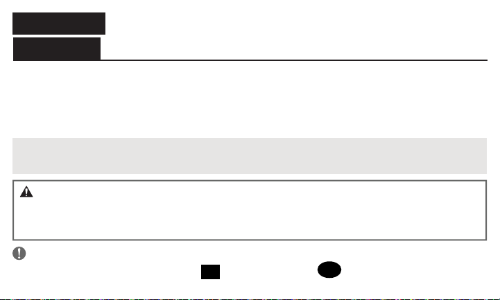
NOTE: Not all hardware included will be used.
WARNING:
This product contains small items that could be a choking hazard if swallowed.
Before starting assembly, verify all parts are included and undamaged. If any parts are missing or damaged,
do not return the damaged item to your dealer; contact Customer Service. Never use damaged parts!
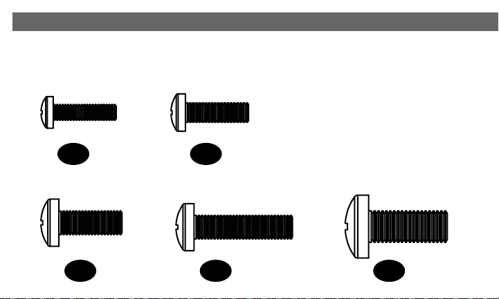
Parts and Hardware for STEP 1
01
x 2
x 2
02
x 2
03
x 2
04
Soundbar
Bracket
Fender
Washer
Keyhole
Screw
Keyhole Screw
Knob
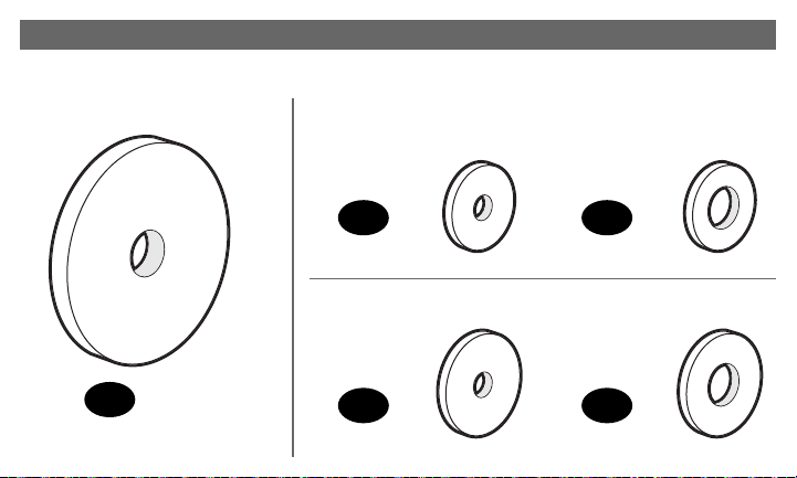
Supplied Parts and Hardware
7
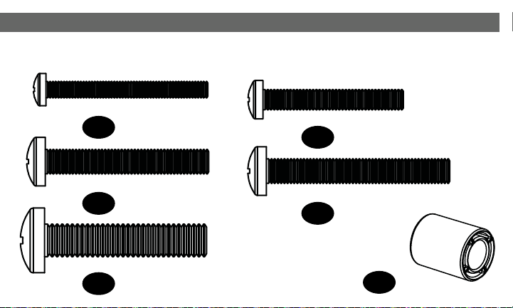
x 2
05
Parts and Hardware for STEP 1 & STEP 3
M4/M5
06
x 4
M4/M5
08
x 4
M6/M8
07
x 8
M6/M8
09
x 4
Mount Spacer
Washer
Large
Washer
Washer
Large
Washer
8
Parts and Hardware for STEP 1 & STEP 3 (continued)
M8 x 20mm
14
x 4
M6 x 25mm
13
x 4
M6 x 16mm
12
x 6
M5 x 16mm
11
x 4
M4 x 16mm
10
x 4
9
M8 x 40mm
19
x 4
M6 x 50mm
18
x 4
22mm
20
x 4
M6 x 40mm
17
x 4
M5 x 40mm
16
x 4
M4 x 40mm
15
x 4
TV Spacers
10
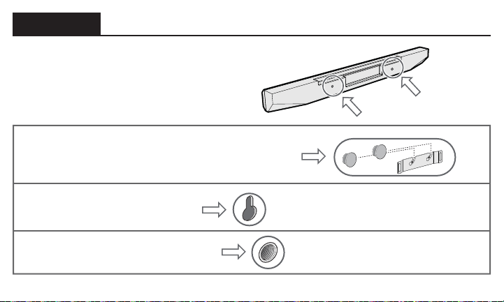
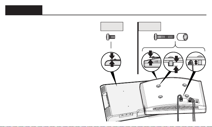
Secure the Brackets onto Your Sound Bar
STEP 1
Look at the mounting holes on the
back of your soundbar to determine
your install method A, B or C.
OPTION A: Rivets with a manufacturer’s
supplied hanger bracket
OPTION B: Key hole slots
OPTION C: Threaded inserts
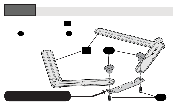
11
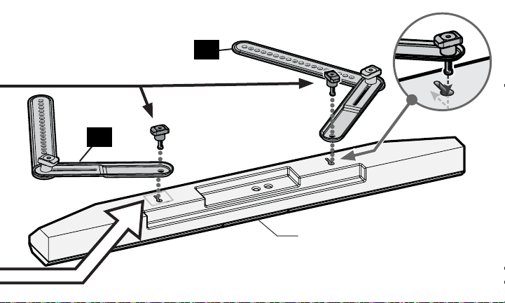
Attach the soundbar brackets
01
to
your soundbar’s hanger bracket with
knobs
04
and keyhole screws
03
.
SOUNDBAR MANUFACTURER
SUPPLIED HANGER BRACKET
Rivets with a Manufacturer’s Supplied Hanger Bracket
OPTION
A
:
04
01
03
Bottom of
Soundbar
& Hanger
Bracket
12
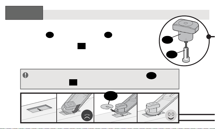
Assemble knobs
04
and keyhole screws
03
.
Attach the soundbar brackets
01
to
your soundbar using the knob assemblies.
Key Hole Slots
04
03
OPTION
B
:
02
IMPORTANT:
If needed, use fender washers
02
under
soundbar bracket
01
to rest fl at onto the soundbar surface.
13
01
01
Bottom of Soundbar
14
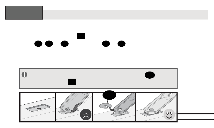
Attach the soundbar brackets
01
to your soundbar using
two screws
10
,
11
or
12
and washers
06
or
07
.
Threaded Inserts
OPTION
C
:
02
IMPORTANT:
If needed, use fender washers
02
under
soundbar bracket
01
to rest fl at onto the soundbar surface.
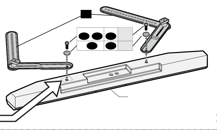
15
Bottom of Soundbar
01
10 11 12
06 07
screws
M4 M5 M6
washers
16
STEP 2
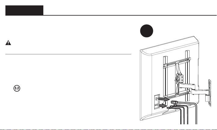
Prepare Your TV (if mounted)
1
If your TV is already mounted:
CAUTION: Follow your TV mount’s manual for
instructions on how to safely remove your TV and TV bracket.
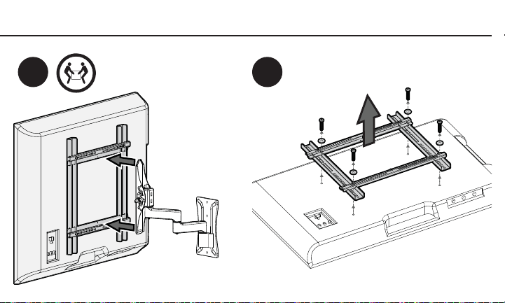
1. Remove any cables attached to your TV.
2. Remove your TV/bracket assembly from your wall
plate, arm assembly, or pillar.
HEAVY! You may need assistance with this step!
3. Remove the TV bracket(s) and hardware from your TV.
17
2 3
18
STEP 3
Install Soundbar Bracket with Your TV Mount
Determine which screw diameter
fits your monitor or TV —
M4, M5, M6, or M8.
• For TVs with a fl at/
unobstructed back,
follow Step 3.1.
*
• For TVs with a rounded/
irregular/obstructed back,
follow Step 3.2.
*
If you need extra space to
accommodate cables, recesses,
or protrusions, follow Step 3.2.
Step 3.1 Step 3.2
19
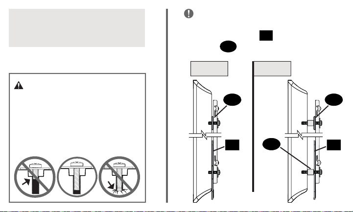
CAUTION: Verify adequate
thread engagement with
your screw/washer/spacer
combination AND all brackets.
— Too short will not hold the TV.
— Too long will damage the TV.
Standard confi gurations shown.
For special applications, contact
Customer Service.
IMPORTANT:
To offset the shift in
height of your TV bracket, due to the
soundbar brackets
01
, you MUST use
washers
05
, in the top hole locations.
Side View
Step 3.1 Step 3.2
05 05
01 01
20
20
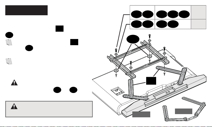
STEP 3.1
Option 1
Option 2
*
WARNING: You must use
the larger washers
08
or
09
(unless they do not fi t your TV bracket).
WARNING: Soundbar MUST
NOT be mounted on TOP of your TV.
05
01
10 11 12 13 14
06 08 07 09
screws
M4 M5 M6 M6 M8
washers
*
*
Install your TV mount’s interface bracket
with soundbar brackets
01
and washers
05
.
NOTE: Sound bar brackets
01
AND
washers
05
install BETWEEN your TV
and TV brackets.
NOTE: Extra screws and washers are
provided, if needed for better fi t
(TV screws are too short - or too long).
21
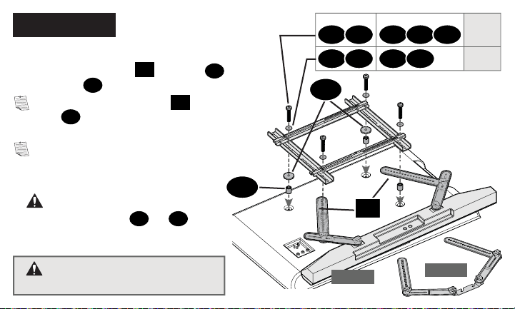
STEP 3.2
Option 1
Option 2
20
*
WARNING: You must use
the larger washers
08
or
09
(unless they do not fi t your TV bracket).
WARNING: Soundbar MUST
NOT be mounted on TOP of your TV.
05
01
15 16 17 18 19
06 08 07 09
screws
M4 M5 M6 M6 M8
washers
*
*
Install your TV mount’s interface bracket
with soundbar brackets
01
, washers
05
and spacers
20
.
NOTE: Sound bar brackets
01
AND
washers
05
install BETWEEN your TV
and TV brackets.
NOTE: Extra screws and washers are
provided, if needed for better fi t
(TV screws are too short - or too long).
22
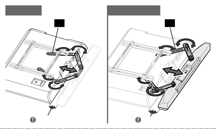
STEP 4
Adjust Soundbar Bracket
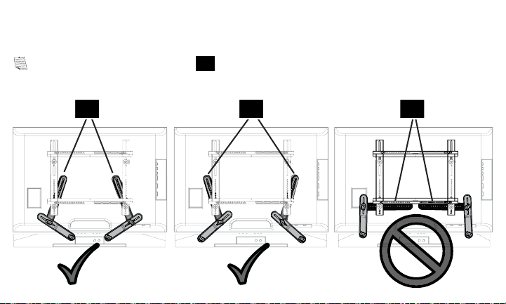
Adjust both arms of soundbar brackets
01
until your soundbar or soundbar
hanger is in your desired position.
NOTE: You may need to reposition the hole locations in soundbar brackets
01
to adjust your soundbar to the desired position.
IMPORTANT:
The fi nal position of your soundbar must be within 2 in. (51 mm)
of the TV.
NOTE: When positioning your soundbar, make sure you will be able to access
the control buttons.
23
≤ 2 in. (51 mm)
≤ 2 in. (51 mm)
OPTIONS B & COPTION A
0101
24
STEP 4
(continued)
CAUTION:
The MIDDLE
connection of
soundbar
brackets
01
must not
extend beyond the edge of
the TV.
01 01
25
01 01 01
NOTE: The soundbar brackets
01
should be positioned as vertically as possible.
26
STEP 5
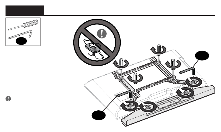
Tighten Connections
Once your soundbar or
soundbar hanger is in
the desired position,
tighten ALL screw and
knob connections.
IMPORTANT! Do not
over-tighten the screws —
this will deform the washers.
H
H
H
27
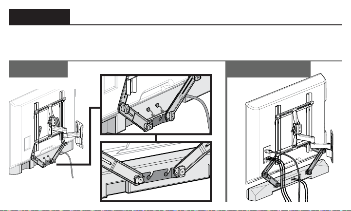
STEP 6
Hang Your TV/Soundbar Assembly
OPTIONS B & COPTION A
Follow your TV wall mount installation manual to hang your TV assembly.

28
ESPAÑOL
Verifi que los siguientes puntos:
Que su televisor, la barra de sonido, la montura de barra de sonido y cualquier accesorio
que vaya a instalar NO EXCEDAN el límite de peso especifi cado del soporte del televisor.
Que va a leer y que comprende estas indicaciones.
Que consulta la documentación proporcionada con su barra de sonido, su televisor y su
soporte de pared para televisor para obtener directrices adicionales.
Que tiene las herramientas necesarias para la instalación.
NO PUEDE UTILIZAR este producto si el soporte de acoplamiento de su televisor: incluye
separadores incorporados o integrados (consulte la Figura 1) o los orifi cios o ranuras de
montaje son superiores a 11 mm [0,43 pulg.] (consulte la Figura 2).
LEA EL MANUAL COMPLETO ANTES DE UTILIZAR ESTE PRODUCTO – CONSERVE ESTAS INSTRUCCIONES
INSTRUCCIONES DE SEGURIDAD IMPORTANTES
Antes de comenzar

29
ESPAÑOL
ADVERTENCIA:
• Esta montura de barra de sonido ha sido diseñada exclusivamente para su uso con soportes
de pared para televisores que cumplan las certifi caciones externas de seguridad.
• Esta montura de barra de sonido ha sido diseñada EXCLUSIVAMENTE para colocarse
DEBAJO del televisor (consulte la Figura 3).
• Esta montura de barra de sonido está diseñado para instalarse y utilizarse exclusivamente
como se especifi ca en este manual. El fabricante no se hace responsable por el armado,
manipulación o uso incorrectos de este producto.
• La pared debe soportar cinco veces el peso combinado del televisor, el soporte y la barra de
sonido.
• No seguir estas instrucciones podría ocasionar una situación inestable que puede causar
daños materiales o lesiones físicas.
Si tiene alguna duda, póngase en contacto con
nuestro servicio de atención al cliente:
1-800-359-5520
30
ESPAÑOL
Restricciones de peso
Límite de peso de SA405
Límite de peso de su soporte para televisor
NO EXCEDA los 6,8 kg (15 lb) en la
montura de barra de sonido
6,8 kg
(15 lb)
PRECAUCIÓN:
Evite posibles lesiones personales y daños materiales.
El peso del televisor, MÁS la montura de la barra de sonido, la barra de sonido y los accesorios DEBE SER
MENOR que el peso máximo permitido para el soporte del televisor. Consulte el peso máximo permitido en
el manual de su soporte para televisor.
0,09 kg
2 lb
__ kg
(__ lb)
__ kg
(__ lb)
__ kg
(__ lb)
(más) (más) (más)
(igual a)
Montura de
barra de sonido
OTROS
Accesorios
Su barra de
sonido
Su TV
PESO
TOTAL
Máximo para su
soporte de TV
PÁGINA 4

31
ESPAÑOL
*El soporte de pared para su televisor puede variar de las
ilustraciones que aparecen en este manual. Tenga en cuenta que
el procedimiento de instalación de la barra de sonido no varía.
Piezas necesarias
Este kit incluye
NOTA: No todos los elementos de sujeción incluidos deberán utilizarse.
ADVERTENCIA:
Este producto contiene piezas pequeñas que, si fuesen tragadas, podrían producir asfixia. Antes de iniciar
el ensamblaje, compruebe que todas las piezas estén incluidas y en buenas condiciones. Si faltan piezas o alguna está dañada, no
devuelva el artículo al distribuidor. Póngase en contacto con el servicio de atención al cliente. Nunca utilice piezas deterioradas.
Piezas y elementos de sujeción para el PASO 1
Piezas y elementos de sujeción para el PASO 1 y el PASO 3
Piezas y elementos de sujeción suministrados
PÁGINA 5
PÁGINA 6
PÁGINA 6
PÁGINA 7
32
ESPAÑOL
Instale el soporte de la barra de sonido
PASO 1
Utilizar el soporte de la barra de
sonidoproporcionado por el fabricante
OPCIÓN
A
:
Ensamble las perillas
04
y tornillos de las ranuras
03
.
Acople los soportes
01
a la barra de sonido utilizando las perillas de ensamblaje.
Ranuras de cerradura
OPCIÓN
B
:
PÁGINA 11
PÁGINA 10
PÁGINA 12
IMPORTANTE: Si lo necesita, use arandelas de protección
02
bajo el soporte de la
barra de sonido
01
para mantener plana la superfi cie.
Observe los orifi cios de montaje situados en la parte trasera de su barra de sonido para
determinar su método de instalación A, B o C. A: Remaches con soporte para colgar
independiente. B: Ranuras de cerradura. C: Orifi cios roscados.
Acople los soportes de la barra de sonido
01
al soporte de la misma con las perillas
04
y
los tornillos de las ranuras
03
.
33
Acople los soportes
01
a la barra de sonido utilizando los dos tornillos
10
,
11
o
12
y
arandelas
06
o
07
.
Orificios roscados
OPCIÓN
C
:
PÁGINA 14
IMPORTANTE: Si lo necesita, use arandelas de protección
02
bajo el soporte de la
barra de sonido
01
para mantener plana la superfi cie.
PASO 2
Prepare su televisor (si está instalado)
Si su televisor ya está instalado en un soporte:
PRECAUCIÓN: Siga las instrucciones del manual de instalación para retirar de forma segura su
televisor y el soporte del mismo.
1. Retire todos los cables conectados al televisor.
2. Retire el conjunto del televisor/soporte de la placa de pared, del brazo o del soporte vertical.
¡ELEMENTO PESADO! Es posible que necesite ayuda en este paso.
3. Retire el soporte del televisor o los elementos de sujeción de su televisor.
PÁGINA 16
ESPAÑOL
34
PASO 3
Instale el soporte de la barra de sonido con el de su televisor
Determine el diámetro de los tornillos para su monitor y su tipo de televisor: M4, M5, M6, o M8.
• Para televisores con dorso plano/libre de obstrucciones, siga el Paso 3-1.
*
• Para televisores con dorso redondeado/irregular/con obstrucciones, siga el Paso 3-2.
*
Si necesita más espacio para cables, concavidades o protuberancias, siga el Paso 3-2.
ESPAÑOL
PRECAUCIÓN: Verifique el enrosque adecuado de la combinación tornillo/arandela/
espaciador y todos los soportes.
— Si es demasiado corto, no sujetará el televisor. — Si es demasiado largo, dañará el televisor.
Se muestra la confi guración estándar. En caso de aplicaciones especiales, comuníquese
con el servicio de atención al cliente.
IMPORTANTE: Para compensar la variación de altura de su soporte para televisor a causa
de los soportes de la barra de sonido
01
UTILICE arandelas
05
, en los orificios superiores.
PÁGINA 18
35
ESPAÑOL
PASO 3-1
PASO 3-2
Monte el soporte de acoplamiento de su montura para televisor con los soportes de la barra de
sonido
01
y arandelas
05
.
Monte el soporte de acoplamiento de su montura para televisor con los soportes de la
barra de sonido
01
, arandelas
05
y separadores
20
.
*
ADVERTENCIA: Debe usar las arandelas más grandes
08
o
09
, a menos que no
sean adecuadas para el soporte del televisor.
*
ADVERTENCIA: Debe usar las arandelas más grandes
08
o
09
, a menos que no
sean adecuadas para el soporte del televisor.
ADVERTENCIA: NO INSTALE la barra de sonido en la PARTE SUPERIOR de su televisor.
ADVERTENCIA: NO INSTALE la barra de sonido en la PARTE SUPERIOR de su televisor.
PÁGINA 20
PÁGINA 21
NOTA: Los soportes y las arandelas barra de sonido instalan entre el televisor y televisión corchetes.
NOTA: Se proporcionan tornillos y arandelas adicionales, si es necesario para un mejor ajuste
(Tornillos de televisión son demasiado cortos - o demasiado largo).
NOTA: Los soportes y las arandelas barra de sonido instalan entre el televisor y televisión corchetes.
NOTA: Se proporcionan tornillos y arandelas adicionales, si es necesario para un mejor ajuste
(Tornillos de televisión son demasiado cortos - o demasiado largo).
36
ESPAÑOL
PASO 4
Ajuste el soporte de la barra de sonido
Ajuste los dos brazos de los soportes de la barra de sonido
01
hasta que esta o su
soporte se encuentren en la posición deseada.
NOTA: Posiblemente necesite reubicar los orifi cios de los soportes de la barra de sonido
01
para ajustarla a la posición deseada.
IMPORTANTE: La posición fi nal de la barra de sonido debe encontrarse a 51 mm (2
pulg.) del televisor como máximo.
NOTA: Al posicionar la barra de sonido, asegúrese de que podrá acceder a los botones
de los controles.
PRECAUCIÓN: La conexión CENTRAL
de los soportes de la barra de
01
no debe
traspasar el borde del televisor.
NOTA: Los soportes de la barra de sonido
01
deben colocarse lo más verticales posible.
PÁGINA 22

37
ESPAÑOL
PASO 5
Cuando la barra de sonido o su soporte se encuentre en la posición deseada, ajuste
TODAS las conexiones de tornillos y perillas.
¡IMPORTANTE! No ajuste en exceso los tornillos ya que podría deformar las arandelas.
PASO 6
Siga las instrucciones del manual de instalación del soporte de pared para televisor para
colgar el módulo.
PÁGINA 26
PÁGINA 27
Ajuste las conexiones
Colgar el conjunto de barra de sonido/televisor

38

39

Thank you for choosing Sanus! Please take a moment to let us know how we did:
Call us: 1-800-359-5520
Leave a review: sanus.com
Email us: [email protected]
Find us on Facebook: SANUS
Follow us on Twitter @sanussystems
SANUS • 6436 City West Parkway • Eden Prairie, MN 55344 USA
6901-602051 00
©2016 Milestone AV Technologies. All rights reserved.
Sanus is a division of Milestone.
All other brand names or marks are used for identifi cation purposes and are
trademarks of their respective owners.
