Loading ...
Loading ...
Connecting Your Wires
3
Wiring Terminations
Terminal Function Description
Rc Input 24 Volt AC Cooling Transformer
(Dual Transformer Systems Only)
Rh Input Power Connection (24 Volt AC Heating
Transformer or Millivolt Power Source)
G Output Fan Control
W1 / E Output (W1) Conventional Heat Relay
(E) Auxiliary/Emergency Heat
O / B / V3 Output (O) Cool Active Reversing Valve
(B) Heat Active Reversing Valve
(V3) Zone Valve Power Close
Y1 Output Compressor Relay
H/D Output (H) Humidification Relay
(D) Dehumidification Relay
C Input 24 Volt AC Transformer Common
S1
S2
Input Optional Remote Sensor (indoor or outdoor)
3 Installer Manual
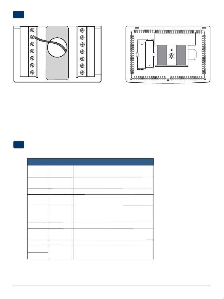
Provide Power
C
24VAC Power Terminal (C)
2
+
+
• For 24 Volt AC power, you must connect the common side of the transformer to the C terminal on the thermostat
sub-base. In dual transformer installations, the transformer common must come from the cooling transformer.
• For battery power, insert the 2 supplied “AA” type alkaline batteries into the battery compartment located in the rear
housing of the thermostat. Make sure to position the Positive (+) and Negative (-) sides of the batteries correctly with
the +/- symbols in the battery compartment.
Batteries Installed as Shown
Loading ...
Loading ...
Loading ...