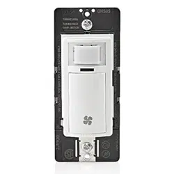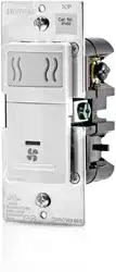
Single Pole Humidity Sensor and Fan Controller
Cat. No. IPHS5 - INDOOR USE ONLY
120VAC, 60Hz - Single Pole Only
Incandescent: 600W - MLV/Fluorescent: 400VA - LED/CFL: 150W - Fan: 1/6Hp
INSTALLATION INSTRUCTIONS
WARNINGS AND CAUTIONS:
• TO AVOID FIRE, SHOCK, OR DEATH: TURN OFF POWER AT CIRCUIT BREAKER OR FUSE AND TEST THAT THE POWER IS OFF BEFORE WIRING!
• TO AVOID PERSONAL INJURY OR PROPERTY DAMAGE, DO NOT install to control a receptacle, or a load in excess of the specified rating.
• To be installed and/or used in accordance with electrical codes and regulations.
• If you are not sure about any part of these instructions, consult an electrician.
WARNINGS AND CAUTIONS:
• Clean outer surface gently with damp cloth only. DO NOT use soaps or cleaning liquids.
• No user serviceable components. DO NOT attempt to service or repair.
• Use this device WITH COPPER OR COPPER CLAD WIRE ONLY.
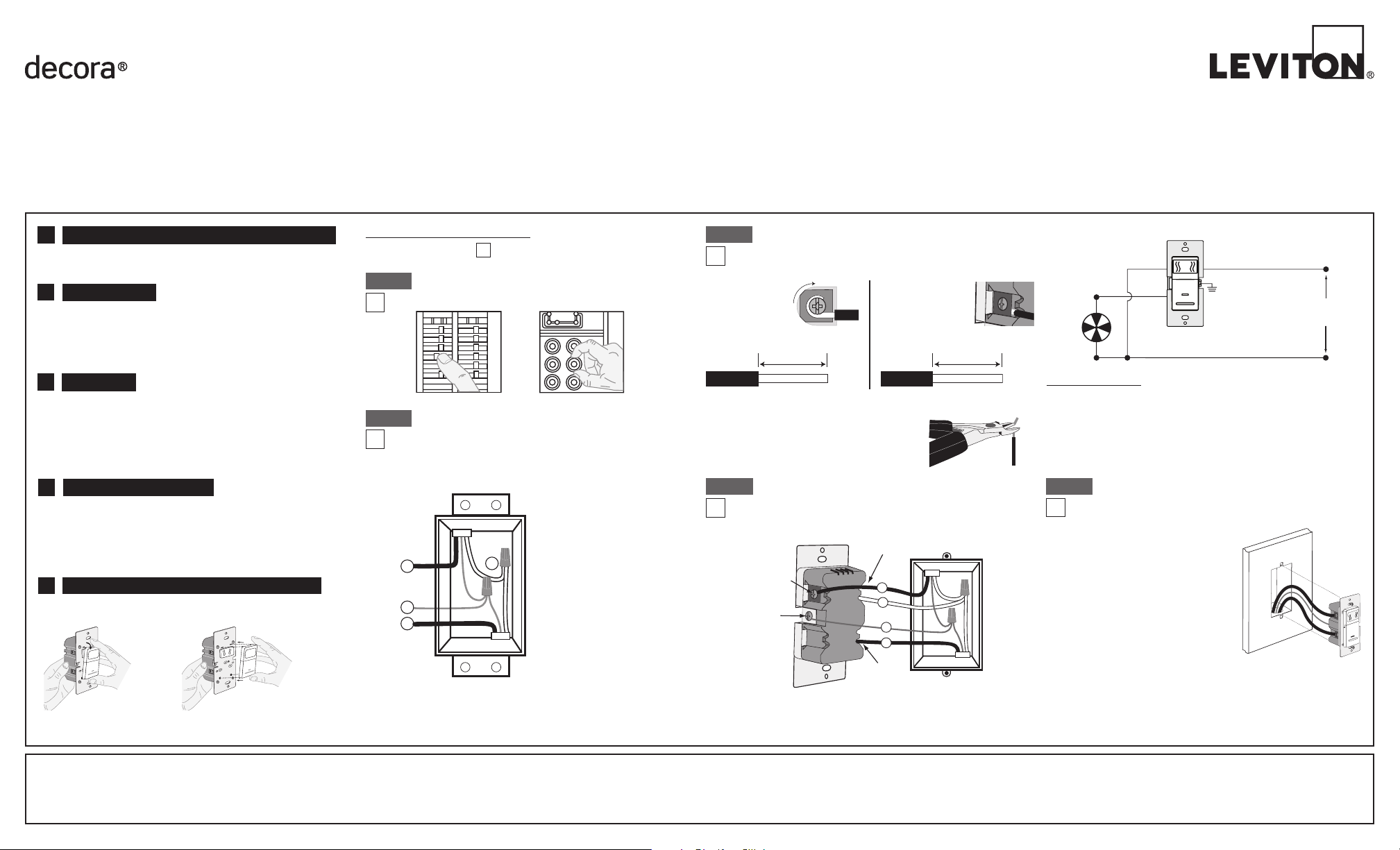
WIRING SENSOR:
Connect wires per WIRING DIAGRAM as follows:
• Green or bare copper wire in wall box to Green terminal screw.
• Line Hot wall box wire to terminal screw marked "BK".
• Load/fan wall box wire to terminal screw marked "RD".
• Neutral wall box wire to terminal screw marked "WH".
• Proceed to Step 5.
BK
WH
RD
4
1
3
2
Terminal Screw
Marked White (WH)
Sensor
Terminal
Screw marked
Red (RD)
Terminal
Screw marked
Black (BK)
Ground
(Green Scre
w)
DI-000-IPHS5-02A
INSTALLING YOUR DEVICE
NOTE: Use check boxes when Steps are completed.
√
ONOFF
ONOFF
ONOFF
ONOFF
ONOFF
ONOFF
ONOFFONOFF
ONOFF
ONOFF
ONOFF
ONOFF
Step 1
WARNING: TO AVOID FIRE, SHOCK, OR DEATH;
TURN OFF POWER at circuit breaker or fuse and test that
power is off before wiring!
Step 2
Identifying your wiring application
(most common):
NOTE: If the wiring in the wall box does not resemble this
configuration, consult an electrician.
2
4
3
1
Single-Pole
1. Line (Hot)
2. Neutral
3. Ground
4. Load
Installation:
Step 4
LIMITED 5 YEAR WARRANTY AND EXCLUSIONS
Leviton warrants to the original consumer purchaser and not for the benefit of anyone else that this product at the time of its sale by Leviton is free of defects in materials and workmanship under normal and proper use for five years from the purchase date. Leviton’s only obligation is to correct
such defects by repair or replacement, at its option. For details visit www.leviton.com or call 1-800-824-3005.This warranty excludes and there is disclaimed liability for labor for removal of this product or reinstallation. This warranty is void if this product is installed improperly or in an
improper environment, overloaded, misused, opened, abused, or altered in any manner, or is not used under normal operating conditions or not in accordance with any labels or instructions. There are no other or implied warranties of any kind, including merchantability and fitness for
a particular purpose, but if any implied warranty is required by the applicable jurisdiction, the duration of any such implied warranty, including merchantability and fitness for a particular purpose, is limited to five years. Leviton is not liable for incidental, indirect, special, or consequential
damages, including without limitation, damage to, or loss of use of, any equipment, lost sales or profits or delay or failure to perform this warranty obligation. The remedies provided herein are the exclusive remedies under this warranty, whether based on contract, tort or otherwise.
Hot (Black)
Neutral (White)
BKWH
Sensor
Blac
k
White
RD
Green
Ground
Line
120 VAC,
60Hz
TOOLS NEEDED TO INSTALL YOUR DEVICE
Slotted/Phillips Screwdriver Electrical Tape Pliers
Pencil Cutters Ruler
A
• Compatible with Incandescent, LED, CFL and Fluorescent loads when
used with combination fan & light fixtures.
• Sensitivity adjustment.
• Built in countdown timer feature for manual operation.
• Automatic ventilation/air circulate mode for continuous operation with
hourly pre-set time outs.
FEATURES C
The IPHS5 is a humidity sensor and switch for control of bath fans and
combination bath fan/lights. The IPHS5 detects changes in humidity for
control of condensation in bathroom application or house ventilation. It
is compatible with bath fans rated at 1/6th HP and fan/light combinations
with single switched load.
DESCRIPTION B
For bathroom applications the device should be placed at a level to
detect steam. Placing the detector directly above a heater or near drafts
is not recommended.
LOCATION / MOUNTING
NOTE: DO NOT use to control a fan/light combination where this is the
only means of illumination.
D
Wire
3/4" (1.9 cm)
Wire
5/8" (1.6 cm)
Preparing and connecting wires:
This device can be wired using side wire terminal screws
or back wire openings. Choose appropriate wire stripping
specifications accordingly.
• Make sure that the ends of the wires from the wall box are straight
(cut if necessary).
• Strip conductors 3/4” (1.9 cm) for side wire
applications or 5/8”
(1.6 cm) for back wire applications.
• Go to Step 4 for wiring instructions.
Cut
(if necessary)
Step 3
TO SIDE WIRE:
Side wire terminals
accept #14-12 AWG
solid and stranded
copper wire.
TO BACK WIRE:
Back wire openings
use #14-12 AWG
solid copper wire
only.
BK
RD
YL 3-Way
CHANGING THE COLOR OF YOUR DEVICE
Push down tabs per
diagram, one at a time
and rotate forward to
release
RESET
RESET
TEST
TEST
2 2
1 3
2 3
1 4
20
off
Lo
Md
off
Hi
cycle
80
Attach new face by inserting
bottom hinge tabs, then
pivot and snap the color
change kit to attach
Your device may include color options. To change color of the face
proceed as follows:
E
• Position all wires to provide room in
outlet wall box for device.
• Ensure the word "TOP" is facing up
on the device strap.
• Partially screw in mounting screws in
the wall box mounting holes.
• Restore power at the circuit breaker
or fuse.
• The Locator LED in the center of the
push pad should be illuminated and
not blinking.
Refer to Locator Light Status Chart
to confirm operational state of device.
• Press and release push pad – This will turn ON the load/fan and
activate the internal countdown timer. The load/fan will turn OFF
after the set time out expires.
• Press and release the push pad again to manually turn OFF the load/fan.
Testing your Device prior to Mounting in Wall Box:
Step 5
NOTE: Dress wires with a bend as shown in diagram in order
to relieve stress when mounting device.
For additional information, contact Leviton’s Techline at
1-800-824-3005 or visit Leviton’s website at www.leviton.com
TROUBLESHOOTING
Load/fan does not turn ON in the presence of humidity (e.g. after a
shower):
• If the sensor is installed in a high humidity area it may be necessary
to adjust the humidistat settings.
Load/fan turns ON throughout the day:
• Change sensor's mode of operation to desired setting.
Load/fan turns ON and OFF during a shower:
• This is normal operation for rooms with good ventilation.
NOTE: DO NOT use to control a fan/light combination where this is the
only means of illumination.
NOTE: The Leviton humidity sensor and fan control will not eliminate
condensation and must be used with a properly sized ventilation fan in
an enclosed space.
DI-000-IPHS5-02A
© 2014 Leviton Mfg. Co., Inc.
This device complies with Part 15 of the FCC Rules. Operation is subject
to following two conditions: (1) this device may not cause harmful
interference, and (2) this device must accept any interference received,
including interference that may cause undesired operation of the device.
This equipment has been tested and found to comply with the limits for
a Class B Digital Device, pursuant to Part 15 of the FCC Rules. These
limits are designed to provide reasonable protection against harmful
interference in a residential installation. This equipment generates, uses,
and can radiate radio frequency energy and, if not installed and used in
accordance with the instructions, may cause harmful interference to radio
communications. However, there is no guarantee that interference will
not occur in a particular installation. If this equipment does cause harmful
interference to radio or television reception, which can be determined
by turning the equipment OFF and ON, the user is encouraged to try to
correct the interference by one or more of the following measures:
• Reorient or relocate the receiving Antenna.
• Increase the separation between the equipment and the receiver.
• Connect the equipment into an outlet on a circuit different from that to
which the receiver is connected.
• Consult the dealer or an experienced radio/tv technician for help.
FCC CAUTION
Any changes or modifications not expressly approved by Leviton Manufacturing
Co., Inc., could void the user's authority to operate the equipment.
FCC COMPLIANCE STATEMENT
FOR CANADA ONLY
For warranty information and/or product returns, residents of Canada
should contact Leviton in writing at Leviton Manufacturing of Canada
Ltd to the attention of the Quality Assurance Department, 165
Hymus Blvd, Pointe-Claire (Quebec), Canada H9R 1E9 or by
telephone at 1 800 405-5320.
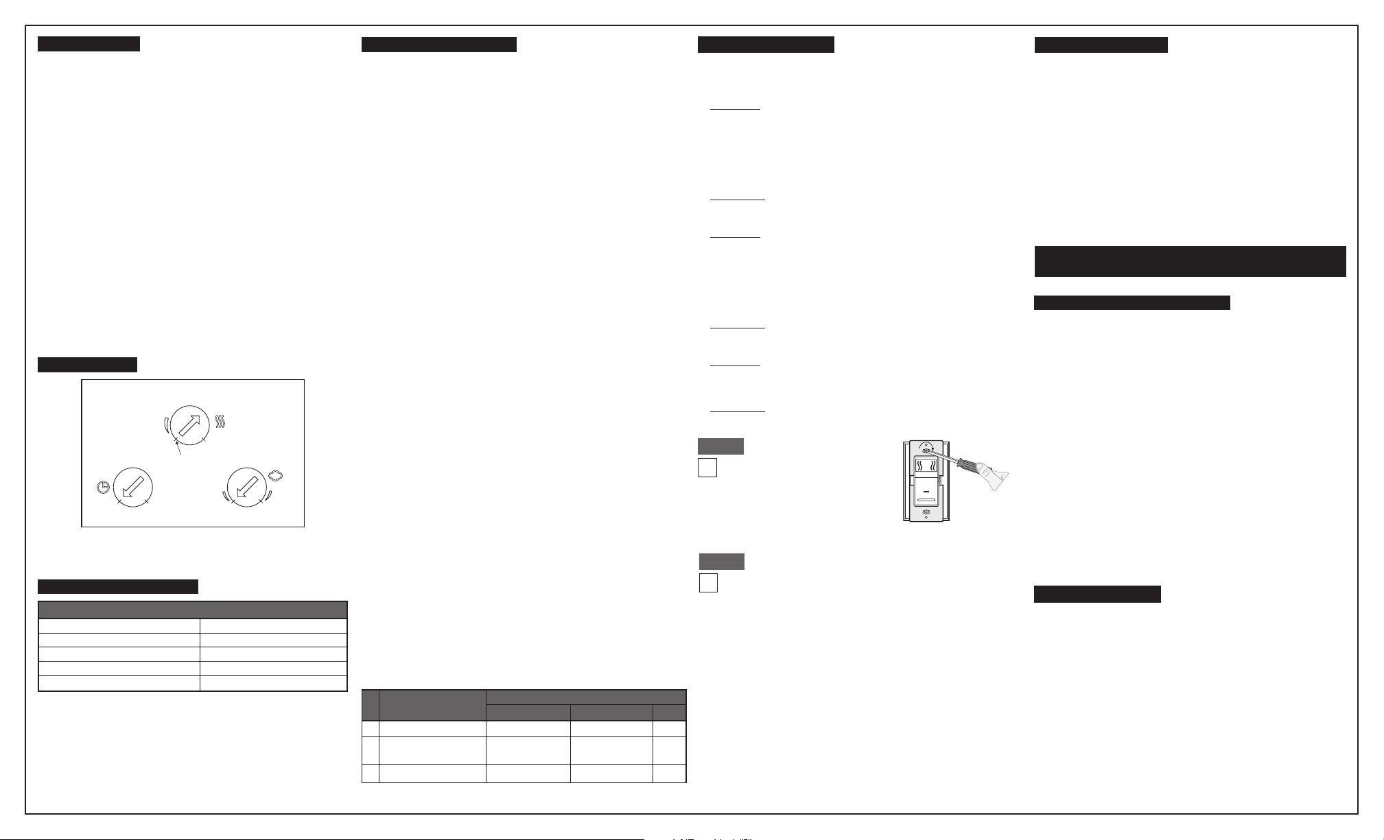
DIAL SETTINGS
With the power restored and the wallplate removed, remove the face
of the device to expose the setting controls (see Color Change Kit
removal on page 1). Use a small screwdriver to make adjustments to
the device as required for the application.
Time - factory default is 10 minutes (1)
1. Adjust the time selector to set the time out duration, which is the
minimum desired length of time the load/fan will remain ON after
being turned on in any mode of operation.
2. Refer to Sensors Dials chart for available time period options.
3. For use with all three Automatic Modes of Operation.
Sensitivity - To reduce false activation, reduce sensitivity.
1. Hi - Default Setting.
2. Medium
3. Low
4. OFF - used in Air Cycle mode.
Humidistat – factory default is OFF (off)
1. OFF - device ignores the humidity set point and controls load/fan
based on detection of excess humidity.
2. Minimum relative humidity set point may be set between 20% and
80% - sets the ambient humidity threshold below which the load/
fan must be operated manually and/or above which the load/fan will
be operated according to one of the automatic modes of operation.
3. Cycle - Only used in Air Cycle Mode.
SENSOR DIALS
Sensitivity
Lo Md
Off
Off
Hi
Time Humidistat
23
14
20 80
cycle
(10 min.) (45 min.)
(20 min.) (30 min.)
(Stop Mark)
NOTE: DO NOT rotate the adjustment dials past the stop marks shown
in the figure above.
ON
LED
OFF
Blinking 2 sec. ON, 2 sec. OFF
Blinking 2 sec. ON, 1/10 sec. OFF
Locator Light Status Chart
Fan (load) OFF
Status
Fan (load) ON
Air Cycle Mode is active
Manual override
LOCATOR LIGHT STATUS
MANUAL OPERATION
Restore Power: Restore power at circuit breaker or fuse.
Installation is complete.
Step 7
Device Mounting:
TURN OFF POWER AT
CIRCUIT BREAKER OR FUSE.
Step 6
Installation may now be
completed by tightening
mounting screws into wall
box. Attach wallplate.
1. Automatic ON/Automatic OFF (Factory Default Mode)
The device is pre-set at the factory to turn ON the load/fan when excess humidity
is detected. The load/fan will turn OFF after the humidity level declines to an
acceptable level and the time out has expired. To set the device back to this
factory default mode:
A. Remove the face of the device to access the adjustment dials. Refer to
Section E on the front page of these instructions.
B. Rotate the Humidistat dial counter clockwise to OFF.
C. Rotate the Sensitivity dial to Hi (default setting). Set to Hi in large rooms
or to increase the sensitivity of the device. Set to Lo in small rooms or to
minimize false activation.
D. Rotate the Time dial to the number 1 for the default time out of 10 minutes
or to the number corresponding to the minimum desired length of time you
wish the load/fan to stay ON once it is turned on in any mode of operation.
Refer to Sensors Dials chart for available time out options.
E. Re-attach the face of the device. Refer to Section E on the front page of
these instructions.
2. Automatic ON/Automatic OFF Mode with humidity set points
The device will automatically turn ON the load/fan only upon detection of excess
humidity above the minimum relative humidity set point:
A. Remove the face of the device to access the adjustment dials. Refer to
Section E on the front page of these instructions.
B. Rotate the Humidistat dial between 20% and 80% to set the minimum
relative humidity set point.
C. Rotate the Sensitivity dial to Hi, Md, or Lo. Set to Hi in large rooms or to
increase the sensitivity of the device. Set to Md in mid sized rooms. Set to
Lo in small rooms or to minimize false activation.
D. Rotate the Time dial to the number 1 for the default time out of 10 minutes
or to the number corresponding to the minimum desired length of time you
wish the load/fan to stay ON once it is turned on in any mode of operation.
Refer to Sensors Dials chart for available time out options.
E. Re-attach the face of the device. Refer to Section E on the front page of
these instructions.
3. Air Cycle Mode
Provides pre-set ventilation ON time for meeting ventilation codes. After the initial
ON time is set by manually turning ON the load/fan with the push pad the device
will provide continuous ON/OFF time every hour. The length of time that the
device will remain ON is determined by the Time dial setting. To set the device to
operate in this mode:
A.Manually turn the device OFF with the push pad if it is ON or wait for the
device to time out automatically.
B. Remove the face of the device to access the adjustment dials.
Refer to Section E on the front page of these instructions.
C. Rotate the Humidistat dial clockwise to the Cycle setting.
D. Rotate the Sensitivity dial to the OFF position.
E. Rotate the Time dial to the number 1 for the default time out of 10 minutes
or to the number corresponding to the minimum desired length of time you
wish the load/fan to stay ON each time it cycles.
F. Re-attach the face of the device. Refer to Section E on the front page of
these instructions.
G. Press the push pad to manually turn the load/fan ON and set the initial ON
time. The device will cycle ON every hour after the initial ON time is set and
remain ON for the length of time set with the Time dial.
NOTE: pressing the push pad while the load/fan is ON in this mode will
manually turn OFF the load/fan and deactivate the Air Cycle mode. To re-
activate Air Cycle mode manually turn ON the load/fan with the push pad
which sets a new initial ON time.
At any time the device can be manually controlled with the push pad on the
front of the device just below the Locator Light.
1. Manual Operation in Auto ON/Auto OFF
Manual ON - When manually turned ON with the push pad in this
mode, and unless the device enters automatic operation by detecting
excess humidity thereafter, the device will time out and turn OFF based
on the time out setting. If the device has been manually turned on and
excess humidity is detected before the time out period has lapsed, the
device will override manual operation and assume control in automatic
mode, turning the load/fan OFF after the humidity level declines to an
acceptable level.
Manual OFF - At any time the push pad can be pressed to manually turn
the load/fan OFF.
2. Manual Operation in Auto ON/Auto OFF with humidity set points
Manual ON - When manually turned ON with the push pad in this mode,
and unless the device enters automatic operation by detecting excess
humidity above the humidity set point thereafter, the device will time
out and turn OFF based on the time out setting. If the device has been
manually turned on and excess humidity is detected above the humidity
set point before the time out period has lapsed, the device will override
manual operation and assume control in automatic mode, turning the
load/fan OFF after the humidity level declines to an acceptable level.
Manual OFF - At any time the push pad can be pressed to manually turn
the load/fan OFF.
3. Manual Operation in Air Cycle Mode
Manual ON - When manually turned ON with the push pad in this mode,
setting the initial ON time, the device will time out and turn OFF based on
the time out setting and continue to cycle ON every hour until it is shut
OFF.
Manual OFF - Pressing the push pad when the load/fan is ON will
disable the Air Cycle Mode until the load/fan is manually turned back ON.
MODES OF OPERATION
Auto ON/Auto OFF
W/ Humidity Set Points
Auto ON/Auto OFF
Modes of Operation
Time
Any
Any
Humidistat
Between 20 and 80
OFF
Sensitivity
Low, Med or High
Low, Med or High1
2
Dials
Air Cycle
Any
Cycle
OFF
3