WARNINGS AND CAUTIONS:
• Ifyouarenotsureaboutanypartoftheseinstructions,consultanelectrician.
• Cleanoutersurfacegentlywithdampclothonly.DO NOT usesoapsorcleaningliquids.
• Nouserserviceablecomponents.DO NOT attempttoserviceorrepair.
• UsethisdeviceWITH COPPER OR COPPER CLAD WIRE ONLY.
WARNINGS AND CAUTIONS:
• TO AVOID FIRE, SHOCK, OR DEATH; TURN OFF POWER AT CIRCUIT BREAKER OR FUSE AND TEST THAT THE
POWER IS OFF BEFORE WIRING!
• Tobeinstalledand/orusedinaccordancewithelectricalcodesandregulations.
• Toavoidoverheatingandpossibledamagetothisdeviceandotherequipment,DO NOTinstalltocontrolareceptacle.
• DO NOT controlaloadinexcessofspeciedratingsoryoumaydamageproperty,orcauseinjuryordeath.
RESET
RESET
TEST
TEST
1 2
0 3
Push down tabs per
diagram, one at a time and
rotate forward to release
1 2
0 3
1 2
0 3
Attach new face by inserting
bottom hinge tabs, then pivot
and snap the color kit to attach
Tools needed to install your Device
Changing the color of your device
Slotted/PhillipsScrewdriver ElectricalTape Pliers
Pencil Cutters Ruler
√
INSTALLING YOUR DEVICE
NOTE: UsecheckboxeswhenStepsarecompleted.
ONOFF
ONOFF
ONOFF
ONOFF
ONOFF
ONOFF
ONOFFONOFF
ONOFF
ONOFF
ONOFF
ONOFF
Step 1
WARNING:TO AVOID FIRE, SHOCK, OR DEATH;
TURN OFF POWERatcircuitbreakerorfuseandtest
thatpowerisoffbeforewiring!
2
4
3
1
Single-Pole
1. Line(Hot)
2. Neutral
3. Ground
4. Load
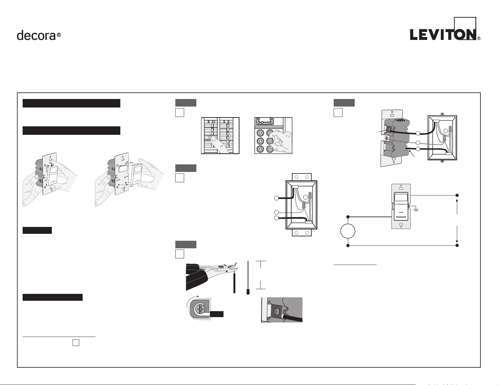
Step 2
Identifying your wiring application
(most common):
NOTE:Ifthewiringinthewallbox
doesnotresembleanyofthese
congurations,consultanelectrician.
WIRING SENSOR:
Connect wires per WIRING DIAGRAM as follows:
NOTE: Agroundconnectionisrequiredtooperate.Usethegroundwire
intheelectricalboxforgroundconnection.Ifthereisnogroundwire,
makesuretheelectricalboxisgroundedandattachthegroundwireto
theboxwithascrew.
• GreenorbarecopperwireinwallboxtoGreenterminalscrew.
• LineHotwallboxwiretoterminalscrewmarked"BK".
• Loadwallboxwiretoterminalscrewmarked"RD".
• ProceedtoStep5.
Hot (Black)
Neutral (White)
Red
Black
Black
White
LOAD
Line
120VAC, 60 Hz
Sensor
Green
Ground
BK
RD
Terminal
Screw marked
Red (RD)
2
Terminal
Screw marked
Black (BK)
4
1
3
Single Pole Wiring Application:
Step 4
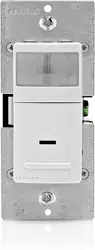
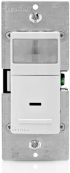
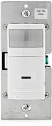
Single Pole Wide View Motion Activated Light Control
Cat. No. IPS02, IPV02 - INDOOR USE ONLY
Ratings:120VAC,60Hz-300WIncandescent-150WLED,CFL-200VAELV,MLV-Fluorescent2.5A-Resistive-1/6thHP
INSTALLATION INSTRUCTIONS
PK-93020-10-00-2A
FEATURES
• Cat.No.IPS02andIPV02haveasensingareaofcoverageof30ft.x
30ft.,andasensingangleof180
O
(seeSensingAreaCoveragegure
onpage2)
• Adjustablelightandtime-delaycontrolsarelocatedonthefrontofthe
device.Seeadjustmentsettingsectiononpage2fordetails.
• LEDindicatorisusedtoalerttheuserofthestatusofthedevice.
• AdjustableTimeDelaysettingfor30seconds,5minutes,
15minutesand30minutes.
• Occupancysensorscanbeconvertedtovacancysensors.
See Adjustment Section page 2.
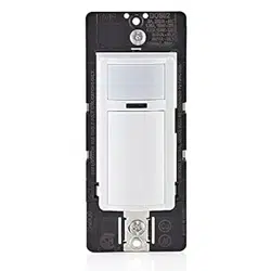
LOCATION / MOUNTING
Thedevicerespondstotemperaturechangesandcareshouldbetaken
whenmountingthedevice.DO NOTmountdirectlyaboveaheatsource,
inalocationwherehotorcolddraftswillblowdirectlyonthesensor,or
whereunintendedmotion(e.g.,hallwaytrafc)willbewithinsensor’s
eld-of-view.
Preparing and connecting wires:
Thisdevicecanbewiredusingsidewireterminalscrews.
Chooseappropriatewirestrippingspecicationsaccordingly.
Strip Gage
(measure bare wire
here or use gage on
back of the sensor)
5/8”
(1.6 cm)
Cut
(if necessary)
Side Wire Connection
Sidewireterminalsaccept#14-12
AWGsolid copper wire only.
Step 3
Back Wire
Backwireopeningsuse#14-12
AWGsolid copper wire only.
BK
RD
YL 3-Way
Yourdevicemayincludecoloroptions.Tochangecoloroftheface
proceedasfollows:
• Makesurethattheendsofthewiresfromthewallboxarestraight
(cut if necessary).
• Removeinsulationfromeachwireinthewallboxasshown.

LIMITED5YEARWARRANTYANDEXCLUSIONS
Levitonwarrantstothe originalconsumerpurchaserand notforthe benetof anyone
else that this product at the time of its sale by Levitonis free of defectsin materials
and workmanship under normaland proper use forfive years from the purchase
date. Leviton’s only obligation is to correct such defects byrepairor replacement, at
itsoption, ifwithin suchveyearperiod theproduct isreturnedprepaid, withproof of
purchasedate, anda descriptionoftheproblemtoLeviton Manufacturing Co., Inc.,
Att: Quality Assurance Department, 201 North Service Road, Melville, New York
11747.Thiswarrantyexcludesandthere isdisclaimed liabilityforlaborforremovalof
thisproductorreinstallation.Thiswarrantyisvoidifthisproductisinstalledimproperly
orinanimproperenvironment,overloaded,misused,opened,abused,oralteredinany
manner,orisnotusedundernormaloperatingconditionsornotinaccordancewithany
labelsorinstructions.There are no other or implied warranties of any kind, including
merchantability and fitness for a particular purpose,but ifany impliedwarranty is
requiredbytheapplicablejurisdiction,thedurationofanysuchimpliedwarranty,including
merchantabilityandtnessforaparticularpurpose,islimitedtoveyears.Leviton is not
liable for incidental, indirect, special, or consequential damages, including without
limitation, damage to, or loss of use of, any equipment, lost sales or profits or delay
or failure to perform this warranty obligation.Theremediesprovidedhereinarethe
exclusive remedies under this warranty, whether basedoncontract,tort or otherwise.
PK-93020-10-00-2A©2012LevitonMfg.Co.,Inc.
• Positionallwirestoprovideroomin
outletwallboxfordevice.
• Ensurethattheword"TOP"is
facingupondevicestrap.
• Partiallyscrewinmountingscrews
inwallboxmountingholes.
• Restorepoweratcircuitbreakerorfuse.
• Wait40secondsforsensortopowerup.
• ForIPS02,lightswillautomaticallyturnON
afterpowerisapplied.
• ForIPV02,presspushpad.Lightsshould
turnON.
If lights still do not turn ON, refer to the
TROUBLESHOOTING section.
Step5
Restore Power:Restorepoweratcircuitbreakeror
fuse.Installation is complete.
Step 7
Device Mounting: TURN OFF POWER AT CIRCUIT
BREAKER OR FUSE.
Step 6
Installationmaynowbe
completedbytightening
mountingscrewsintowall
box.Attachwallplate.
OPERATION
NOTE: Dresswireswithabendas
shownindiagraminordertorelieve
stresswhenmountingdevice.
For additional information, contact Leviton’s Techline at
1-800-824-3005orvisitLeviton’swebsiteatwww.leviton.com
ThisproductiscoveredbyU.S.Pat.No.7,924,155&correspondingforeignpatents.
©2012LevitonManufacturingCo.,Inc.AllRightsIncludingTradeDressRightsReserved
DECORAisatrademarkofLevitonManufacturingCo.,Inc.registeredintheUnited
States,Canada,MexicoandChina.
ADJUSTMENT SETTINGS
TROUBLESHOOTING
Lights do not operate with push pad and LED indicator does not
blink when motion is present:
• Ensurepropergroundconnectionispresentinthewallbox.
Whenconrmed,verifywiringconnectionstosensor.
Lights do not switch ON when motion is detected (IPS02):
• Motionisbeyondsensingrange,moveclosertoswitch.
• Adjustthelightleveladjustmenttowardlighter(counterclockwise),
dependingonroomconditions.
Lights always stay ON:
• ChecktimedelaysettingsandcomparetohowlongthelightsstayON.
• Ensurethatnomotionoccursincoverageareafortimeselected.
• Checkthatswitchisnotinstallednearaheatsource(e.g.,stove,lights,
heatvents)ordetectingmotionfromanadjacentarea(e.g.,hallway
trafc).Ifso,switchmayhavetoberelocated.
Lights do not turn ON - IPV02:
• Checkthatcontrolisinstalledcorrectly.
• CheckthatpowerisON.
• Checkthatlightbulbisfunctioning.
NOTE:Ifproblemscontinue,consultanelectrician.
IPS02
Auto On: LightswillautomaticallyturnONwhen
roomisoccupiedormotionisdetected.
TheIPS02willswitchlightsOFFwhenno
motionisdetectedinun-occupiedroomafterset
periodoftime.
Time delay adjustment:Refertosectionon
Adjustmentsettings.
TheIPS02willmanuallyturn-onlightsorthe
loadbydepressingtheON/OFFpaddleonthe
device.TheIPS02canbesettoonlyturnONby
thepushpad(noautomaticONoperation)byadjustingtheambientlight
controltothe"0"position.
IPV02
Manual On:TheIPV02requirestheusertomanuallyturn-onlightsorthe
loadbydepressingtheON/OFFpaddleonthedevice.
Thelightsorloadwillautomaticallyturn-offwhentheroomisleft
un-occupiedforasetperiodoftime.
Time delay adjustment:RefertosectiononAdjustmentsettings.
Locator Light LED:
LEDblinksonceevery2secondswhenmotionisdetectedandiftheload
isONorOFF.
FCC COMPLIANCE STATEMENT
ThisdevicecomplieswithPart15oftheFCCRules.Operationissubjecttofollowing
twoconditions:(1)thisdevicemaynotcauseharmfulinterference,and(2)thisdevice
mustacceptanyinterferencereceived,includinginterferencethatmaycauseundesired
operationofthedevice.
ThisequipmenthasbeentestedandfoundtocomplywiththelimitsforaClassBDigital
Device,pursuanttoPart15oftheFCCRules.Theselimitsaredesignedtoprovide
reasonableprotectionagainstharmfulinterferenceinaresidentialinstallation.This
equipmentgenerates,uses,andcanradiateradiofrequencyenergyand,ifnotinstalled
andusedinaccordancewiththeinstructions,maycauseharmfulinterferencetoradio
communications.However,thereisnoguaranteethatinterferencewillnotoccurina
particularinstallation.Ifthisequipmentdoescauseharmfulinterferencetoradioor
televisionreception,whichcanbedeterminedbyturningtheequipmentOFFandON,
theuserisencouragedtotrytocorrecttheinterferencebyoneormoreofthefollowing
measures:
•ReorientorrelocatethereceivingAntenna.
•Increasetheseparationbetweentheequipmentandthereceiver.
•Connecttheequipmentintoanoutletonacircuitdifferentfromthattowhichthe
receiverisconnected.
•Consultthedealeroranexperiencedradio/tvtechnicianforhelp.
FCC CAUTION
AnychangesormodicationsnotexpresslyapprovedbyLevitonManufacturingCo.,Inc.,
couldvoidtheuser'sauthoritytooperatetheequipment.
SENSING AREA COVERAGE
Field-of-View (Horizontal)
Side (Vertical) Field-of-View
Testing your Device prior to mounting in
wall box:
1. Withpowerrestoredandwallplateremoved,removefaceofdeviceto
exposesettingcontrols,seecolorchangeinstructionsinpage1.Use
yourngerorasmallscrewdrivertoadjustthelightsensitivityandtime
settingsonthedeviceasfollows:
Light Level Adjustment:
• Turnthecontrolclockwise.LightswillturnONinlighterconditions.
• Turnthecontrolcounterclockwise.LightswillturnONinlesslighting
conditions.
Time Selection:
• Adjustthetimeselectortothedesiredlengthoftimethelightsareto
remainON.LightswillremainONfrom30secondsto30minutesafter
theroomisvacated.
• Turnthecontrolclockwise.LightswillremainONupto30minutes.
• Turnthecontrolcounterclockwise.LightswillremainONupto30
seconds.
2. Testthatthelightlevelandtimeselectionareasdesired.Ifnot,repeat
adjustmentsuntilsatised.
3. Mountwallplate.INSTALLATION IS COMPLETE.
Lens
Push
Pad
Locator
Light
1.5m
5ft
30ft
9.1m
30ft
9.1m
6ft
1.7m
1.8m
6ft
5ft
1.5m
30ft
9.1m
1.4m
4ft
8.4m
27ft
2.1m
7ft
1.5m
5ft
1.2m
4ft
1.7m
6ft
2.6m
8ft
Light Level
Adjustment
Time
Selection
1 2
0 3
1 2
0 3
0
1
2
3
Settings
30Sec
5Min
15Min
30Min
Time
NOTE:TooperatetheIPS02asavacancysensor(ManualON/AutoOFF):
rotatethelightlevelsensitivityfullycounterclockwise.
FOR CANADA ONLY
Forwarrantyinformationand/orproductreturns,residentsofCanadashouldcontact
LevitoninwritingatLeviton Manufacturing of Canada Ltd to the attention of
theQualityAssuranceDepartment,165HymusBlvd,Pointe-Claire(Quebec),
Canada H9R 1E9orbytelephoneat1800405-5320.