Single Pole (One location) or 3-Way (Multi-location)
Electronic Countdown Timer Switch
Cat. No. LTB15, LTB30, LTB60, LTB02, LTB12 Lighted
20A Resistive/Inductive, 1800W Incandescent, 1HP
120VAC, 60Hz
INSTALLATION INSTRUCTIONS
WARNINGS AND CAUTIONS:
• Tobeinstalledand/orusedinaccordancewithappropriateelectricalcodesandregulations.
• Ifyouareunsureaboutanypartoftheseinstructions,consultanelectrician.
• Levitonelectroniccountdowntimerswitchesarenotcompatiblewithstandard3-wayor4-wayswitches.Theymustbeusedwithcompatible
Vizia
+
®
ON/OFFremoteswitches.
• Recommendedminimumwallboxdepthis2-1/2”.
WARNINGS AND CAUTIONS:
• Disconnect power at circuit breaker or fuse when servicing, installing or removing fixture.
• Useonlyone(1)Levitonelectroniccountdowntimerswitchinamulti-locationcircuitwithupto9coordinatingremoteswitches
withoutLEDsorupto4matchingremoteswitcheswithLEDs
.
• Maximumwirelengthfromtimerswitchtoallinstalledremoteswitchescannotexceed300ft(90m).
• Usethisdeviceonlywithcopper or copper clad wire only.
IMPORTANT:For3-Wayapplications,notethatoneofthescrewterminals
fromtheoldswitchbeingremovedwillusuallybeadifferentcolor(Black)
orlabeledCommon.Tagthatwirewithelectricaltapeandidentifyasthe
common(LineorLoad)inboththeswitchwallboxandremotewallbox.
TOOLS NEEDED TO INSTALL YOUR TIMER SWITCH
Slotted/PhillipsScrewdriver ElectricalTape Pliers
Pencil Cutters Ruler
WIRING TIMER SWITCH:
Connect wires per WIRING DIAGRAM as follows:
• GreenorbarecopperwireinwallboxtoGreenlead.
• LineHotwallboxwiretoBlacklead.
• LoadwallboxwiretoRedlead.
• LineNeutralwallboxwiretoWhitelead.
• TimerSwitchYellow/RedleadshouldhaveRedinsulationlabelafxed.
• Proceed to Step 5.
Hot (Black)
Neutral (White)
Coordinating Remote Switch (no LED)
YL/RD
YL/RD
RD
WH
RD
BK
Bla c k
BK WH
White
Line
120VAC, 60Hz
Green
Ground
Green
Ground
(u n used )
(u n used )
Load
Timer Switch
WIRING TIMER SWITCH:
Connect wires per WIRING DIAGRAM as follows:
NOTE:ThetimerswitchmustbeinstalledinawallboxthathasaLine
Hot connection.
NOTE:Maximumwirelengthfromtimerswitchtoallinstalledremote
switchescannotexceed300ft(90m).
• GreenorbarecopperwireinwallboxtoGreenlead.
• LineHot(common)wallboxwireidentied(tagged)whenremoving
oldswitchtoBlacklead.
• FirstTravelerwallboxwiretoRedlead(note wire color).
• RemoveRedinsulatinglabelfromYellow/Redlead.
• SecondTravelerwallboxwiretoYellow/Redlead(note wire color).
Thistravelerfromthetimerswitchmustgototheterminalscrewon
theremoteswitchmarked"YL/RD".
• LineNeutralwallboxwiretoWhitelead.
WIRING VIZIA COORDINATING REMOTE SWITCH:
Connect wires per WIRING DIAGRAM as follows:
NOTE:"BK"and"RD"terminalsoncoordinatingremoteswitchare
unused.Tightenbothscrews.
NOTE:Maximumwirelengthfromtimerswitchtolastremoteswitch
is300ft(90m).
• GreenorbarecopperwireinwallboxtoGreenterminalscrew.
• Loadwallboxwireidentied(tagged)whenremovingoldswitchto
First Traveler (note color as above).
• SecondTravelerwallboxwire(note color as above)toterminal
screwmarked"YL/RD".Thistravelerfromtheremoteswitchmustgo
totheYellow/Redleadofthetimerswitch.
• RemoveWhiteinsulatinglabelfromterminalscrewmarked"WH".
• LineNeutralwallboxwiretoterminalscrewmarked"WH".
• ProceedtoStep5.
ONOFF
ONOFF
ONOFF
ONOFF
ONOFF
ONOFF
ONOFFONOFF
ONOFF
ONOFF
ONOFF
ONOFF
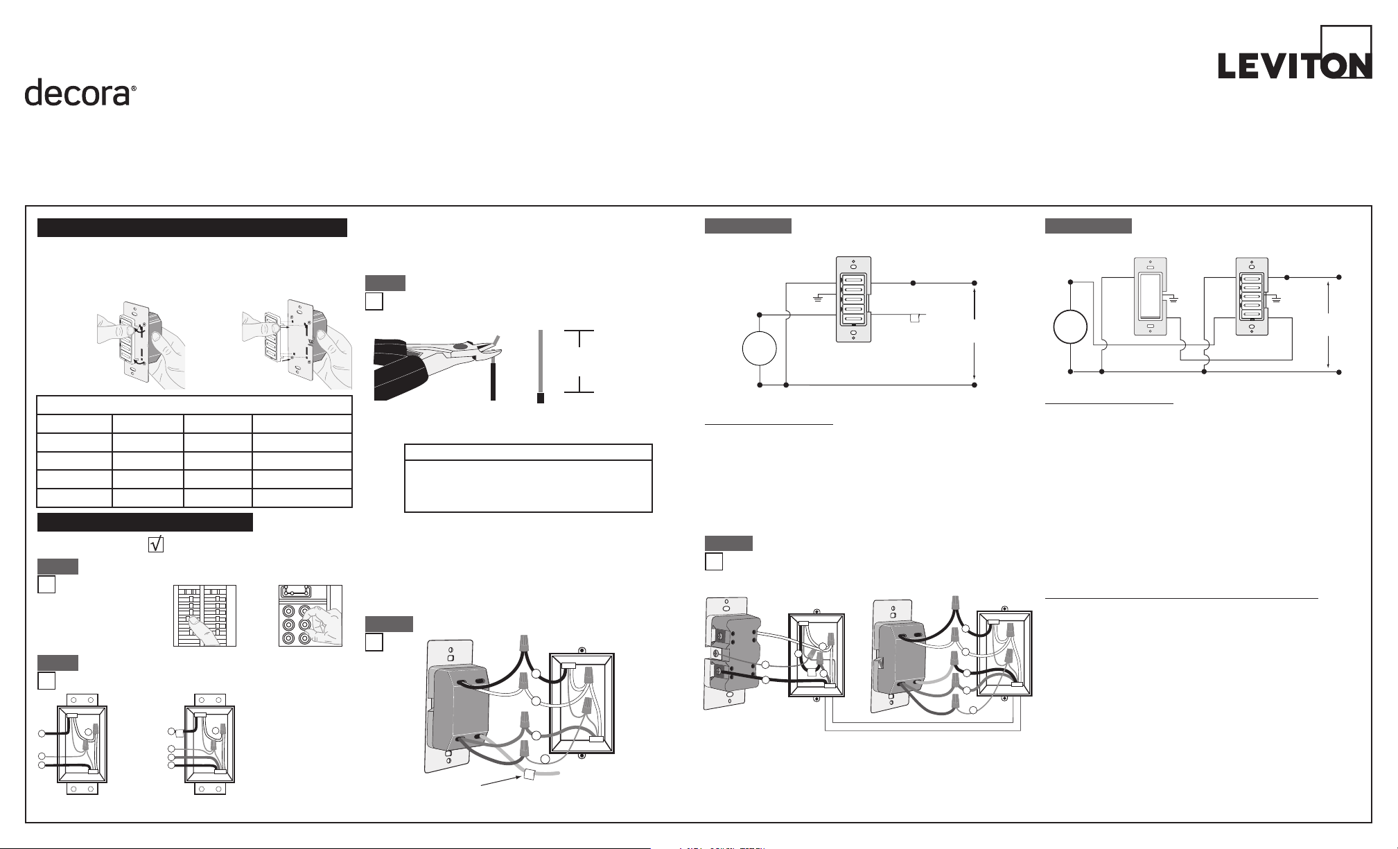
WARNING: TO AVOID FIRE SHOCK OR DEATH; TURN
OFF POWER atcircuitbreakerorfuseandtestthatpoweris
offbeforewiring!
Step 1
2
4
3
1
2
4
1
5
3
Single Pole
1. Line (Hot)
2. Neutral
3.Ground
4. Load
3-Way
1. Line or Load
(see
IMPORTANT
instruction)
2. Neutral
3.Ground
4. First Traveler – note color
5. Second Traveler – note
color.
Identifying your wiring application (most common):
NOTE:Ifthewiringinyourwallboxdoesnotresembleanyof
thesecongurations,consultanelectrician.
Step 2
Insulating label:
This wire is used in 3-way installations only.
For single pole installations, do not remove
this insulating label.
1
2
Black
White
Red
4
Yellow/Red
Green
3
Single Pole Wiring Application:
Step 4a
Step 4a cont'd
2
1
4
BK
RD
YL/RD
Coordinating Remote Switch Timer Switch
5
3
1
2
Black
White
Red
4
Yellow/Red
Green
3
5
WH
3-Way Wiring with Vizia
+
Coordinating Remote
Switch (no LED) Application:
Step 4b
• Makesurethattheendsofthewiresfromthewallboxare
straight (cut if necessary).
• Removeinsulationfromeachwireinthewallboxasshown.
• ForSingle-PoleApplication,gotoStep4a.
• For3-WayCoordinatingRemoteSwitch(noLEDs)Application,gotoStep4b.
• For3-WayMatchingRemoteSwitch(withLEDs)Application,gotoStep4c.
Step 3
Preparing and connecting wires:
Pulloffpre-cutinsulationfromtimerswitchleads.Makesure
thattheendsofthewiresfromthewallboxarestraight(cutif
necessary).Removeinsulationfromeachwireinthewallbox
asshown:
5/8"
(1.6 cm)
Strip Gage
(measure bare
wire here)
Cut
(if necessary)
Step 4b cont'd
Changing the color of your device:
Yourdevicemayincludecoloroptions.Tochangecoloroftheface,
proceedasfollows:
Push in side
at tab to release
Line up tabs and
press in sides one
at a time to attach
For non-standard wiring applications, refer to
Wire Nut and Connector Size Chart
WIRE CONNECTOR / # OF COND. COMBINATION CHART
1 - #12 w/ 1 to 3 #14, #16 or #18
2 - #12 w/ 1 to 2 #16 or #18
1 - #14 w/ 1 to 4 #16 or #18
2 - #14 w/ 1 to 3 #16 or #18
Timer Switch
Insulating
Label
Black
Hot (Black)Black
Line
120 VAC, 60Hz
Neutral (White)
Red Yellow/Red
White
White
Green
Ground
Load
PK-93796-10-00-2A
NOTE:UsecheckboxeswhenStepsarecompleted.
INSTALLING YOUR TIMER SWITCH
+
MAXIMUM LOAD PER TIMER FOR MULTI-DEVICE INSTALLATIONS
Load Single TwoDevices More than 2 devices
Resistive Load 20A(2400W) 16A(1920W) 16A(1920W)
Incandescent Load
1800W 1800W 1800W
Inductive Load 20A 16A 16A
Motor Load 1HP 1HP 1HP
NOTE:Formatchingremotew/LEDsinstallation,
the First TravelerbecomesLineHot.
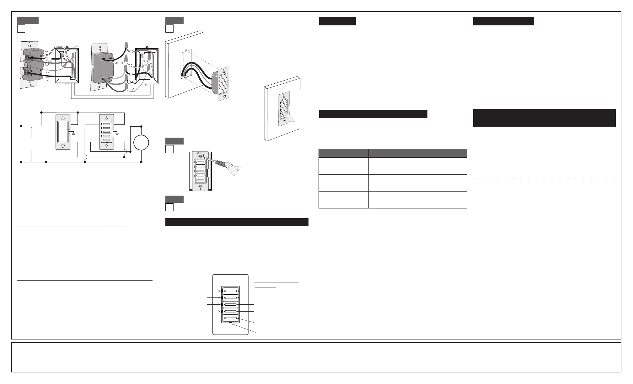
NOTE:ThetimerswitchmustbeinstalledinawallboxthathasaLoad
connection.Thematchingremoteswitchmustbeinstalledinawallbox
withaLineHotconnectionandaNeutralconnection.ANeutralwireto
thematchingremoteswitchneedstobeaddedasshown.
Ifyouareunsureaboutanypartoftheseinstructions,consultan
electrician.
NOTE:Maximumwirelengthfromtimerswitchtoallinstalledremote
switchescannotexceed300ft(90m).
WIRING VIZIA MATCHING REMOTE SWITCH
(wall box with Line Hot connection):
Connect wires per WIRING DIAGRAM as follows:
• GreenorbarecopperwireinwallboxtoGreenterminalscrew.
• LineHot(common)wallboxwireidentied(tagged)whenremoving
oldswitchandFirstTravelertoremoteterminalscrewmarked"BK".
• SecondTravelerwallboxwirefromswitchtoremoteterminal
screwmarked"YL/RD"(note wire color).Thistravelerfromtheremote
mustgototheYellow/Redleadonthetimerswitch.
• LineNeutralwallboxwiretoremoteterminalscrewmarked"WH".
WIRING TIMER SWITCH (wall box with Load connection):
Connect wires per WIRING DIAGRAM as follows:
• GreenorbarecopperwireinwallboxtoGreenlead.
• Loadwallboxwireidentied(tagged)whenremovingoldswitchto
Red lead.
• FirstTravelerLineHottoBlacklead.
• RemoveRedinsulatinglabelfromYellow/Redlead.
• SecondTravelerwallboxwire(note color as above)toYellow/Red
lead.Thistravelerfromthetimerswitchmustgototheterminalscrew
ontheremoteswitchmarked"YL/RD".
• LineNeutralwallboxwiretoWhitelead.
• ProceedtoStep5.
3-Way Wiring with Vizia
+
Matching
Remote Switch (w/LED) Application:
BK
RD
YL/RD
Additional
Neutral Wire
Matching Remote Switch
3
5
1
2
4
Timer Switch
1
2
Black
White
Red
4
Yellow/Red
Green
3
5
WH
Hot (Bla c k )
Neutral (White)
Timer SwitchMatching Remote Switch (with LED)
YL/RD
RD YL/RD
WH
BK
BK
Black
White
Line
120VAC, 60Hz
WH
Load
Green
Ground
Green
Ground
• Restorepoweratcircuitbreakerorfuse.
• Pressanytimerbuttontoturntheloadon.
If the load does not turn ON, refer to the
TROUBLESHOOTING section.
Timer Switch Mounting:
TURN OFF POWER AT CIRCUIT BREAKER OR FUSE.
Installationmaynowbecompletedby
tighteningmountingscrewsintowallbox.
Attachwallplate.
LIMITED 5 YEAR WARRANTY AND EXCLUSIONS
LevitonwarrantstotheoriginalconsumerpurchaserandnotforthebenetofanyoneelsethatthisproductatthetimeofitssalebyLevitonisfreeofdefectsinmaterialsandworkmanshipundernormalandproperuseforveyearsfromthepurchasedate.Leviton’sonlyobligationistocorrectsuchdefectsbyrepairorreplacement,
atitsoption,ifwithinsuchveyearperiodtheproductisreturned prepaid, with proof of purchase date,andadescription of the problemtoLeviton Manufacturing Co., Inc., Att: Quality Assurance Department, 201 North Service Road, Melville, NY 11747.Thiswarrantyexcludesandthereisdisclaimedliabilityforlabor for
removalofthis productorreinstallation.This warrantyis voidif thisproductisinstalledimproperlyorin animproperenvironment,overloaded,misused,opened,abused,or alteredinanymanner,orisnotused undernormaloperatingconditionsornot inaccordancewithanylabelsorinstructions.There are no other or implied
warranties of any kind, including merchantability and fitness for a particular purpose, but ifany implied warrantyis requiredbythe applicablejurisdiction, theduration of anysuch impliedwarranty, including merchantability and tness for a particular purpose, islimited tove years. Leviton is not liable for incidental,
indirect, special, or consequential damages, including without limitation, damage to, or loss of use of, any equipment, lost sales or profits or delay or failure to perform this warranty obligation.Theremediesprovidedhereinaretheexclusiveremediesunderthiswarranty,whetherbasedoncontract,tortorotherwise.
PK-93796-10-00-2A
©2009LevitonMfg.Co.,Inc.
Testing your Timer Switch prior to mounting in
wall box:
• Positionallwirestoprovideroomin
outletwallboxfordevice.
• Ensurethattheword“TOP”isfacing
upondevicestrap.
• Partiallyscrewinmountingscrewsin
wallboxmountingholes.
NOTE:Dresswireswithabendas
shownindiagraminordertorelieve
stresswhenmountingdevice.
Step 5 Step 4c
Step 6
Restore Power:
Restorepoweratcircuitbreakerorfuse.
Installation is complete.
Step 7
1. ToturntheloadONpressoneofthetimerbuttons.ThegreenLED
adjacenttothatbuttonwillilluminateandthetimerwillbeginto
countdownfortheselectedtimerperiod.
2. Toselectadifferentcountdowntimepressthebuttoncorrespondingto
thedesiredtime.TheLEDadjacenttothatbuttonwillilluminateandthe
timerwillbegincountdownfromthenewselection.
3. ToturntheloadOFFpresstheOFFbuttonorwaituntiltheselected
amountoftimehaspassed.TheLEDadjacenttoeachbuttonwill
extinguishastimepassestothenextpresetlevel.
OPERATION
For additional information, contact Leviton’s
Techline at 1-800-824-3005 or visit Leviton’s
website at www.leviton.com
CoveredbyoneormoreUS&Foreign
Patentsandpatentspending
©2009LevitonManufacturingCo.,Inc.
AllRightsIncludingTradeDressRightsReserved
•Degreeofprotectionprovided:IP20
•TypeofAction:1Q
FCC COMPLIANCE STATEMENT
ThisdevicecomplieswithPart15oftheFCCRules.Operationissubject
tofollowingtwoconditions:(1)thisdevicemaynotcauseharmful
interference,and(2)thisdevicemustacceptanyinterferencereceived,
includinginterferencethatmaycauseundesiredoperationofthedevice.
Thisequipmenthasbeentestedandfoundtocomplywiththelimitsfor
aClassBDigitalDevice,pursuanttoPart15oftheFCCRules.These
limitsaredesignedtoprovidereasonableprotectionagainstharmful
interferenceinaresidentialinstallation.Thisequipmentgenerates,uses,
andcanradiateradiofrequencyenergyand,ifnotinstalledandusedin
accordancewiththeinstructions,maycauseharmfulinterferencetoradio
communications.However,thereisnoguaranteethatinterferencewill
notoccurinaparticularinstallation.Ifthisequipmentdoescauseharmful
interferencetoradioortelevisionreception,whichcanbedetermined
byturningtheequipmentOFFandON,theuserisencouragedtotryto
correcttheinterferencebyoneormoreofthefollowingmeasures:
• ReorientorrelocatethereceivingAntenna.
• Increasetheseparationbetweentheequipmentandthereceiver.
• Connecttheequipmentintoanoutletonacircuitdifferentfromthatto
whichthereceiverisconnected.
• Consultthedealeroranexperiencedradio/tvtechnicianforhelp.
FCC CAUTION
AnychangesormodicationsnotexpresslyapprovedbyLeviton
ManufacturingCo.,Inc.,couldvoidtheuser'sauthoritytooperatethe
equipment.
TROUBLESHOOTING
• IntermittentOperation
-Loadhasabadconnection.
-Wiresnotsecuredrmlytoleadsoftimerswitch
and/orremoteswitch.
• LoaddoesnotturnONandLocatorLEDdoesnotturnON
- Circuitbreakerorfusehastripped.
-Loadisburnedout.
-Neutralconnectionisnotwired.
• Remotedoesnotoperateload
-Ensurethattotalwirelengthdoesnotexceed300ft(90m).
-Ensurethataneutralwireisusedwithmatchingremoteswitches.
Timer Select Mode - You can change the time outs on your timer
without buying a new device!
ADVANCED PROGRAMMING FEATURE
• Four(4)TimerbuttonsandanOFFbutton.
• EachtimerbuttonhasanadjacentgreenLEDtoindicatethecurrent
countdowntime.
• ThegreenbottomLEDisONwhentheloadisOFFandisOFFwhen
the load is ON.
• Yourtimerswitchcanbeeasilyprogrammedtofunctionas1of4timers.
• LTB02isnotprogrammableasa12hourtimerbutcanbeprogrammedto
functionasanyoftheothertimers.
Timer Override
TooverridetheTimercountdownpressandholdthetopbuttonforseveral
seconds.ThelocatorLEDwillturnambertoindicatetheEXTENDEDON
state.InthisstatethetimerwillautomaticallyturnOFFafter24hours.Toexit
theEXTENDEDONstatepressanyofthetimerbuttonsortheOFFswitch.
Yourtimercanbeprogrammedtofunctionasanyofthetimersinthe
tablebelow:
NOTE:IfyouchangetheONtimesofyourtimertheprintedfacewillno
longermatchtheONtimes.Atimerchangekitshouldbepurchasedto
alleviate this situation.
To select different on times please follow the subsequent steps:
1. Press and hold the 1st and 3rdtimerbuttonstoenterSelectTimerMode.
2. ThecurrentactiveTimerLEDwillashgreentoindicatethedeviceisin
SelectTimerMode.
3. Pressthebutton(fromthetableabove)correspondingwiththetimeouts
you desire.
4. ThenewTimerbuttonwillbrieyashtodemonstratethetimermode
chosen.
5. PressingtheOFFbuttonwillsaveprogrammingandexitprogramming
mode.Thetimerwillalsoexitprogrammingmodeautomaticallyifno
buttonsarepressedfor3minutes.
Multi-Location Control
TheTimercanbeturnedONorOFFfromanyoftheVizia
+
®
Remote
Switchlocations.ThedefaultONtimewhenaremoteispressedtoturn
theloadONwillbethelastcountdowntimechosen.Thetimercanbe
controlledfromupto10locationsusingVizia
+
CoordinatingRemote
Switchesorupto5locationsusingVizia
+
MatchingRemoteSwitches.
NOTE: Sharinganeutralwiremaycauseimproperoperation.Connectall
timerstothesamephaseorrunaseperateneutraltoeachphase.
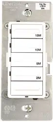
FEATURES OF YOUR COUNTDOWN TIMER SWITCH
Button 1 - Longest ON time
Button 2
LED indicator
lights
Locator LED
Button 3
Button 4 - Shortest ON time
OFF switch
Timer buttons
+
Timer Switch Number Buttons Time outs
LTB02 1(toptimerbutton) 15m,30m,1hr,2hr
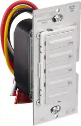
LTB12 1(toptimerbutton) 2,4,8,12hours
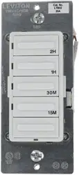
LTB60 2 10,20,30,60minutes
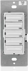
LTB30 3 5,10,15,30minutes
LTB15 4(bottomtimerbutton) 2,5,10,15minutes
N/A 5-OFFbutton N/A