WARNINGS AND CAUTIONS:
• TO AVOID FIRE, SHOCK, OR DEATH; TURN OFF POWER AT CIRCUIT BREAKER OR FUSE AND TEST THAT THE POWER IS OFF BEFORE WIRING!
• Tobeinstalledand/orusedinaccordancewithelectricalcodesandregulations.
• Toavoidoverheatingandpossibledamagetothisdeviceandotherequipment,DO NOTinstalltocontrolareceptacle,amotor,oratransformer-operatedappliance
otherthanapplicablespeciedlightingload:IncandescentandLED.
• Whenusingina3-wayapplicationuseonesensorandonestandard3-wayswitch.Cannotbeusedwithanothersensor,orina4-wayapplication.
WARNINGS AND CAUTIONS:
• Ifyouarenotsureaboutanypartoftheseinstructions,consultanelectrician.
• Cleanoutersurfacegentlywithdampclothonly.DO NOT usesoapsorcleaningliquids.
• Nouserserviceablecomponents.DO NOT attempttoserviceorrepair.
• UsethisdeviceWITH COPPER OR COPPER CLAD WIRE ONLY.
RESET
RESET
TEST
TEST
1 2
0 3
Push down tabs per
diagram, one at a time and
rotate forward to release
1 2
0 3
1 2
0 3
Attach new face by inserting
bottom hinge tabs, then pivot
and snap the color kit to attach
TOOLS NEEDED TO INSTALL YOUR DEVICE
Slotted/PhillipsScrewdriver ElectricalTape Pliers
Pencil Cutters Ruler
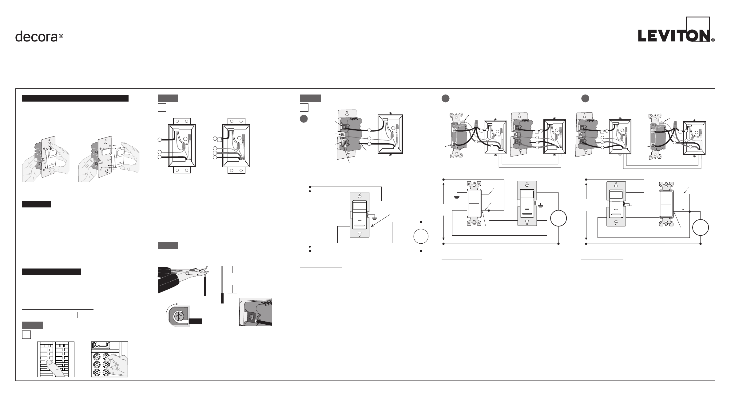
Changing the color of your device:
Yourdevicemayincludecoloroptions.Tochangecolorofthe
faceproceedasfollows:
BK
RD
3-Way
Terminal
Screw marked
Red (RD)
2
Terminal
Screw marked
Black (BK)
Brass
Terminal Screw
Marked 3-Way
Terminal Label:
Use Terminal for 3-Way Applications Only.
For Single Pole Applications, Do Not Remove This Label.
4
1
3
Ground
(Green Screw)
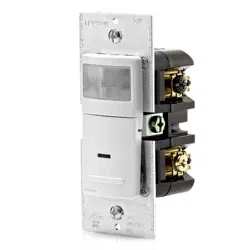
Sensor
Single Pole and 3-Way Wide View Motion Activated Light Control
Cat. No. IPS06, IPV06 - INDOOR USE ONLY
Ratings:120VAC,60Hz600WIncandescent&150WLED
INSTALLATION INSTRUCTIONS
PK-93978-10-00-2A
FEATURES
• Cat.No.IPS06andIPV06haveasensingareaofcoverageof
30ft.x30ft.,andasensingangleof180
O
(see Sensing Area
Coverage figure on page 2).
• Adjustablelightandtime-delaycontrolsarelocatedonthefront
ofthedevice(See adjustment setting section on page 2
for details).
• LEDindicatorisusedtoalerttheuserofthestatusofthedevice.
• AdjustableTimeDelaysettingfor30seconds,5min,15min
&30min.
• Occupancysensorcanbeconvertedtoavacancysensor
(See adjustment settings on page 2).
LOCATION / MOUNTING
Thedevicerespondstotemperaturechangesandcareshouldbe
takenwhenmountingthedevice.DO NOTmountdirectlyabove
aheatsource,inalocationwherehotorcolddraftswillblow
directlyonthesensor,orwhereunintendedmotion(e.g.,hallway
trafc)willbewithinsensor’seld-of-view.
Sensor is located in electrical box with LINE
connection:
C
Hot (Black)
Neutral (White)
BK
LOAD
Line
120VAC
60 Hz
Sensor
Green
Ground
3-Way/
Brass
3-Way Switch
Common Terminal
(Black Screw)
Pigtail
Pigtail
Green
Ground
RD
First Traveler
Second Traveler
Hot (Black)
Neutral (White)
BK
LOAD
Line
120VAC
60 Hz
Sensor
Green
Ground
Green
Ground
3-Way/
Brass
3-Way Switch
Common Terminal
(Black Screw)
Pigtail
Pigtail
First Traveler
Second Traveler
RD
BK
RD
3-Way
2
3-Way Switch
2
Sensor
1
3
5
Common
Terminal
(Black
Screw)
Ground
(Green Screw)
1
4
4
3
5
Common
Terminal
(Black
Screw)
Ground
(Green Screw)
BK
RD
3-Way
2
Sensor
3
5
1
4
3-Way Switch
2
1
5
4
3
B
Sensor is located in electrical box with LOAD
connection:
WIRING SWITCH:
Connect wires per WIRING DIAGRAM as follows:
• GreenorbarecopperwireinwallboxtoGreenterminalscrew.
• OnepigtailwiretotheBlackscrewterminalmarked"COM"and
onepigtailwiretotheBrassterminal(same side of switch).
• Connectthefollowing4wiresusinganappropriatelysized
wirenut:
1. Common/Linewire(identified in step 2).
2. SecondTravelerwire(note color from step 2).
3. Twopigtailwiresfromthe3-wayswitch.
• FirstTravelerwallboxwire(note color from step 2)to
Brassscrewterminalontheswitch(opposite side from the
Black screw).
WIRING SENSOR:
Connect wires per WIRING DIAGRAM as follows:
• GreenorbarecopperwireinwallboxtoGreenterminalscrew.
• Common/Loadwallboxwireidentiedwhenremovingold
switch(step 2)toterminalscrewmarked"BK".
• FirstTravelerwallboxwire(note color from step 2)toterminal
screwmarked"3-way".
• SecondTravelerwallboxwire(note color from step 2)to
terminalscrewmarked"RD".ThisTravelerfromtheswitchmust
gototheterminalscrewonthesensormarked"RD".
WIRING SENSOR:
Connect wires per WIRING DIAGRAM as follows:
• GreenorbarecopperwireinwallboxtoGreenterminalscrew.
• Common/Linewallboxwireidentiedwhenremovingoldswitch
(step 2)toterminalscrewmarked"BK".
• FirstTravelerwallboxwire(note color from step 2)toterminal
screwmarked"RD".
• SecondTravelerwallboxwire(note color from step 2)to
terminalscrewmarked"3-way".
WIRING SWITCH:
Connect wires per WIRING DIAGRAM as follows:
• GreenorbarecopperwireinwallboxtoGreenterminalscrew.
• OnepigtailwiretotheBlackscrewterminalmarked"COM"and
aonepigtailwiretothebrassterminal(samesideofswitch)
• Connectthefollowing4wiresusinganappropriatelysized
wirenut:
1. Common/Loadwire(identified in step 2).
2. FirstTravelerwire(note color from step 2).
3. Twopigtailwiresfromthe3-Wayswitch.
• SecondTravelerwallboxwire(note color from step 2)to
Brassscrewterminalontheswitch(opposite side from the
Black screw).
IMPORTANT:For3-wayapplications,notethatoneofthescrew
terminalsfromtheoldswitchbeingremovedwillusuallybea
differentcolor(Black)orlabeledCommon.Tagthatwirewith
electricaltapeandidentifyasthecommon(LineorLoad)inboththe
sensorwallboxandremotewallbox.
3-Way
1. LineorLoad (See important
instruction below)
2. Neutral
3. Ground
4. FirstTraveler–notecolor
5. SecondTraveler–notecolor
2
4
3
1
Single-Pole
1. Line(Hot)
2. Neutral
3. Ground
4. Load
Step 2
Identifying your wiring application
(most common):
NOTE:Ifthewiringinthewallboxdoesnotresembleany
ofthesecongurations,consultanelectrician.
Preparing and connecting wires:
Thisdevicecanbewiredusingsidewireterminal
screws.Chooseappropriatewirestripping
specicationsaccordingly.
• Makesurethattheendsofthewiresfromthewallboxarestraight
(cut if necessary).
• Removeinsulationfromeachwireinthewallboxasshown.
• For Single Pole Application, go to Step 4A.
• For 3-Way Application with the sensor on the Load side, go to Step 4B.
• For 3-Way Application with the sensor on the Line side, go to Step 4C.
Strip Gage
(measure bare wire
here or use gage on
back of the sensor)
5/8”
(1.6 cm)
Cut
(if necessary)
Side Wire Connection
Sidewireterminalsaccept#14-12
AWGsolid copper wire only.
Step 3
Back Wire
Connection
Backwireopeningsuse#14-12
AWGsolid copper wire only.
BK
RD
YL 3-Way
2
4
1
5
3
√
INSTALLING YOUR DEVICE
NOTE: UsecheckboxeswhenStepsarecompleted.
ONOFF
ONOFF
ONOFF
ONOFF
ONOFF
ONOFF
ONOFFONOFF
ONOFF
ONOFF
ONOFF
ONOFF
Step 1
WARNING:TO AVOID FIRE, SHOCK, OR
DEATH; TURN OFF POWERatcircuitbreakeror
fuseandtestthatpowerisoffbeforewiring!
WIRING SENSOR:
Connect wires per WIRING DIAGRAM as follows:
• GreenorbarecopperwireinwallboxtoGreenterminalscrew.
• LineHotwallboxwiretoterminalscrewmarked"BK".
• Loadwallboxwiretoterminalscrewmarked"RD".
• Terminalscrewmarked"3-way"shouldhaveRedinsulationlabel
afxed.
NOTE: Ifinsulatinglabelisnotafxedtoterminalscrewmarked
"3-way",useelectricaltapetocover.
• ProceedtoStep5.
Use Terminal for 3-Way
Applications Only.
For Single Pole Applications,
Do Not Remove This Label.
Hot (Black)
Neutral (White)
RD
Black
BK
White
LOAD
Line
120VAC, 60 Hz
Sensor
Green
Ground
3-Way
(Brass
Screw)
Step 4
Single Pole Wiring Application:
A
3-Way Wiring with 3-Way Switch Application:
Whenconnectingthesensorfor3-waycontrol,rstchoosewhich
wallswitchlocationthesensorwillbeinstalledin.Next,identify
whichelectricalboxhasthelineconnection.Ifthelineconnection
isintheboxwherethestandard3-wayswitchislocated,usewiring
diagram4B.Ifthelineconnectionisintheboxwherethesensoris
located,usewiringdiagram4C.
NOTE: Apairofshortpigtailwireswillbeneededforconnectionto
the3-wayswitch.
LIMITED 5 YEAR WARRANTY AND EXCLUSIONS
Levitonwarrants to theoriginal consumerpurchaser and notforthe benet ofanyoneelsethat thisproductat thetime of itssale by Levitonis freeof defectsin materials and workmanshipunder normal andproperuse forveyearsfrom thepurchase date. Leviton’s only obligationisto correct suchdefectsbyrepair or replacement,at its option,if withinsuch veyearperiod theproduct isreturned prepaid,with
proofofpurchase date, and adescription oftheproblemto Leviton Manufacturing Co., Inc., Att: Quality Assurance Department, 201 North Service Road, Melville, New York 11747.Thiswarrantyexcludesand thereisdisclaimed liability forlabor forremovalofthis product orreinstallation.Thiswarrantyisvoidifthis product isinstalledimproperly orinan improperenvironment,overloaded,misused, opened,
abused,or altered in any manner,or is not used under normal operating conditions or not in accordance with any labels or instructions.There are no other or implied warranties of any kind, including merchantability and fitness for a particular purpose, butif any implied warranty is required by the applicable jurisdiction, the duration of any such implied warranty, including merchantability and tness for
a particular purpose, is limited to veyears.Leviton is not liable for incidental, indirect, special, or consequential damages, including without limitation, damage to, or loss of use of, any equipment, lost sales or profits or delay or failure to perform this warranty obligation.The remedies provided hereinare the exclusiveremedies underthis warranty, whether based on contract, tort or otherwise.
PK-93978-10-00-2A
©2012LevitonMfg.Co.,Inc.
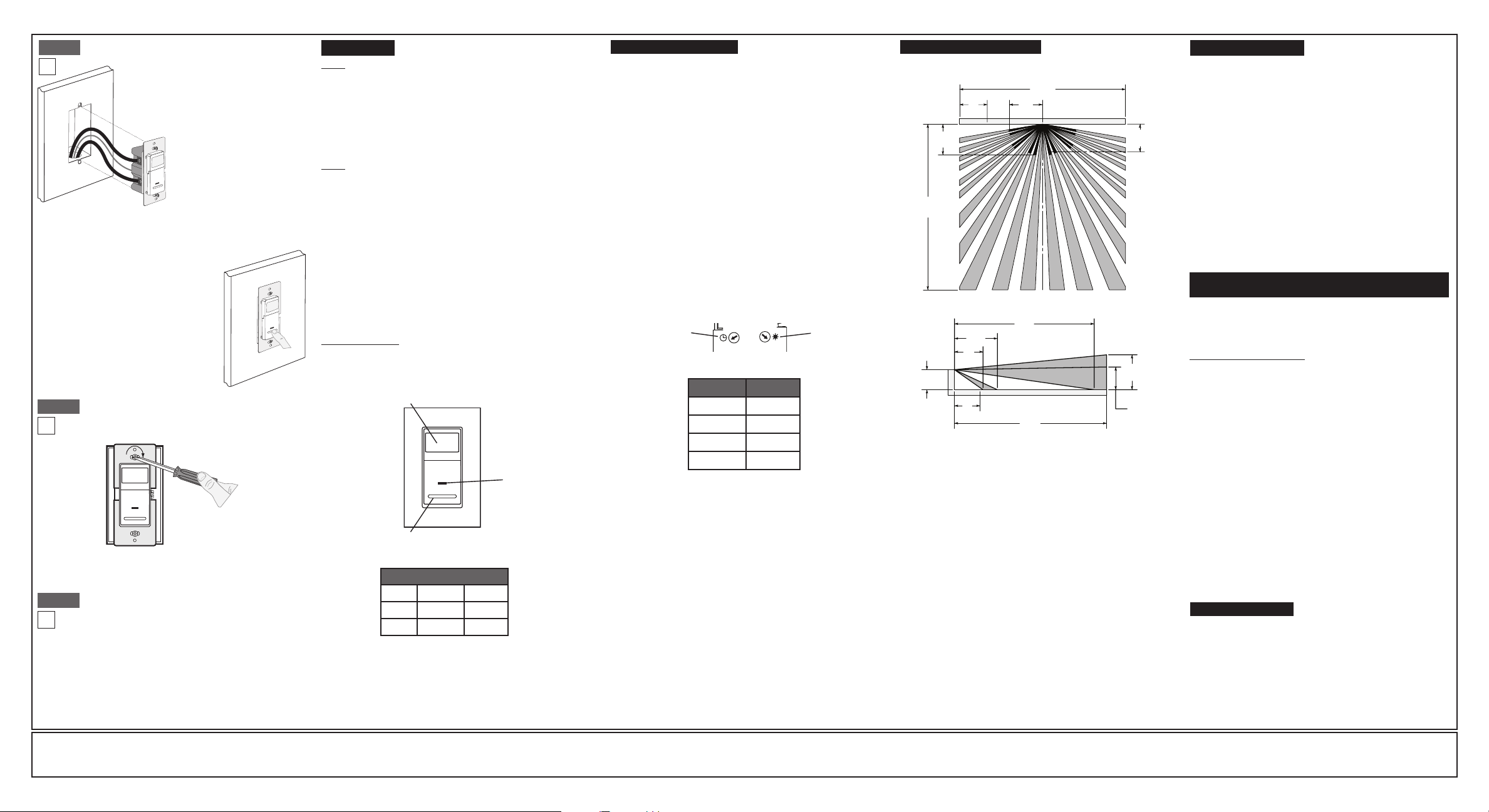
• Positionallwirestoprovideroominoutletwallboxfordevice.
• Ensurethattheword"TOP"isfacingupondevicestrap.
• Partiallyscrewinmountingscrewsinwallboxmountingholes.
• Restorepoweratcircuitbreakerorfuse.
• ForIPS06lightswillautomaticallyturnON
afterpowerisapplied.
• ForIPV06pressamdreleasepushpadto
turnthelightsON.
See Locator Light Status chart to
confirm the operational state of the
device.
If lights still do not turn ON, refer to the
TROUBLESHOOTING section.
Testing your Device prior to mounting in
wall box:
Step 5
Restore Power:Restorepoweratcircuitbreaker
orfuse.
Installation is complete.
Step 7
Device Mounting:
TURN OFF POWER AT CIRCUIT BREAKER OR
FUSE.
Step 6
Installationmaynowbecompletedbytighteningmountingscrews
intowallbox.Attachwallplate.
OPERATION
Locator Light LED:
IPS06:
LEDblinkswhenmotionisdetectedandiftheloadisONorOFF.
IPV06: LEDblinkswhenmotionisdetectedandwhenloadisON.
LEDwillremainilluminatedwhenloadisOFF.
NOTE: Dresswireswithabendas
shownindiagraminordertorelieve
stresswhenmountingdevice.
For additional information, contact Leviton’s Techline at
1-800-824-3005 or visit Leviton’s website at www.leviton.com
ThisproductiscoveredbyU.S.Pat.No.7,924,155
andcorrespondingforeignpatents.
©2012LevitonManufacturingCo.,Inc.
AllRightsIncludingTradeDressRightsReserved
TROUBLESHOOTING
Lights do not switch ON - IPS06:
• Motionisbeyondsensingrange,moveclosertoswitch.
• Adjustthelightleveladjustmenttowardlighterordarker,
dependingonroomconditions.
Lights always stay ON:
• Checktimedelaysettingsandcomparetohowlongthelights
stayON.
• Besurethatnomotionoccursincoverageareafortime
selected.
• Checkthatswitchisnotinstallednearaheatsource(e.g.,stove,
lights,heatvents)ordetectingmotionfromanadjacentarea
(e.g.,hallwaytrafc).Ifso,switchmayhavetoberelocated.
Lights do not turn ON - IPV06:
• Checkthatswitchisinstalledcorrectly.
• CheckthatpowerisON.
• Checkthatlightbulbisfunctioning.
NOTE:Ifproblemscontinue,consultanelectrician.
ADJUSTMENT SETTINGS
1. Withpowerrestoredandwallplateremoved,removefaceof
devicetoexposesettingcontrols,seecolorchangeinstructionsin
page1.Useasmallscrewdrivertoadjustthelightsensitivityand
timesettingsonthedeviceasfollows:
Light Level Adjustment:
•Adjustthelightleveldialclockwise.LightswillturnONinlighter
conditions.
•Adjustthelightleveldialcounterclockwise.LightswillturnON
inlesslightingconditions.
•Adjustinglightlevelfullycounterclockwisewillrequiremanual
operationofthesensor.
Time Selection:
• Adjustthetimeselectordialtothedesiredlengthoftimethe
lightsaretoremainON.LightswillremainONfrom30seconds
to30minutesaftertheroomisvacated.
• Adjustthetimeselectordialclockwisetoincreasetheduration
oftheONtimeupto30minutes.
• Adjustthetimeselectordialcounterclockwisetodecreasethe
durationoftheONtimedownto30sec.
2. Testthatthelightlevelandtimeselectionareasdesired.
Ifnot,repeatadjustmentsuntilsatised.
3. Mountwallplate.INSTALLATION IS COMPLETE.
IPS06
Auto On: LightswillautomaticallyturnONwhenroomisoccupiedor
motionisdetected.TheIPS06willswitchlightsOFFwhennomotion
isdetectedinun-occupiedroomaftersetperiodoftime.
Time delay adjustment:RefertosectiononAdjustmentSettings.
Light level adjustment:RefertosectiononAdjustmentsettings.
Manual ON: TheIPS06willmanuallyturnONlightsortheloadby
depressingthepushpadonthedevice.
IPV06
Manual ON:TheIPV06requirestheusertomanuallyturnONlights
ortheloadbydepressingthepushpadonthedevice.
ThelightsorloadwillautomaticallyturnOFFwhentheroomisleft
un-occupiedforasetperiodoftime.
TheIPV06canalsobeturnedoffmanuallybydepressingthe
pushpad.
Time delay adjustment:refertosectiononAdjustmentsettings
Light Level
Adjustment
Time Selection
1 2
0 3
1 2
0 3
Settings Time
0 30Sec
1 5Min
2 15Min
3 30Min
Push
Pad
LOCATOR LIGHT STATUS
LOAD
IPS06 IPV06
OFF
Blinking Lit
ON
Blinking Blinking
NOTE:Ina3-wayapplication,the3wayswitchprovidestheabilityto
manuallyswitchtheloadONfromasecondlocation.Thesensorwill
timeoutandswitchtheloadOFFoncemotionisnolongerdetected
andthetimedelayexpires.
SENSING AREA COVERAGE
Field-of-View (Horizontal)
Side (Vertical) Field-of-View
1.5m
5ft
30ft
9.1m
30ft
9.1m
6ft
1.7m
1.8m
6ft
5ft
1.5m
30ft
9.1m
1.4m
4ft
8.4m
27ft
2.1m
7ft
1.5m
5ft
1.2m
4ft
1.7m
6ft
2.6m
8ft
Locator
Light
Lens
FCC COMPLIANCE STATEMENT
ThisdevicecomplieswithPart15oftheFCCRules.Operationissubjectto
followingtwoconditions:(1)thisdevicemaynotcauseharmfulinterference,
and(2)thisdevicemustacceptanyinterferencereceived,including
interferencethatmaycauseundesiredoperationofthedevice.
Thisequipmenthasbeentestedandfoundtocomplywiththelimitsfora
ClassBDigitalDevice,pursuanttoPart15oftheFCCRules.Theselimits
aredesignedtoprovidereasonableprotectionagainstharmfulinterference
inaresidentialinstallation.Thisequipmentgenerates,uses,andcanradiate
radiofrequencyenergyand,ifnotinstalledandusedinaccordancewith
theinstructions,maycauseharmfulinterferencetoradiocommunications.
However,thereisnoguaranteethatinterferencewillnotoccurinaparticular
installation.Ifthisequipmentdoescauseharmfulinterferencetoradioor
televisionreception,whichcanbedeterminedbyturningtheequipmentOFF
andON,theuserisencouragedtotrytocorrecttheinterferencebyoneor
moreofthefollowingmeasures:
•ReorientorrelocatethereceivingAntenna.
•Increasetheseparationbetweentheequipmentandthereceiver.
•Connecttheequipmentintoanoutletonacircuitdifferentfromthatto
whichthereceiverisconnected.
•Consultthedealeroranexperiencedradio/tvtechnicianforhelp.
FCC CAUTION
AnychangesormodicationsnotexpresslyapprovedbyLeviton
ManufacturingCo.,Inc.,couldvoidtheuser'sauthoritytooperatethe
equipment.
NOTE: TooperatetheIPS06asavacancysensor(manualON/Auto
OFF)-rotatethelightleveladjustmentfullycounterclockwise.
FOR CANADA ONLY
Forwarrantyinformationand/orproductreturns,residents
ofCanadashouldcontactLevitoninwritingatLeviton
Manufacturing of Canada Ltd to the attention of the Quality
Assurance Department, 165 Hymus Blvd, Pointe-Claire
(Quebec), Canada H9R 1E9orbytelephoneat1 800 405-5320.