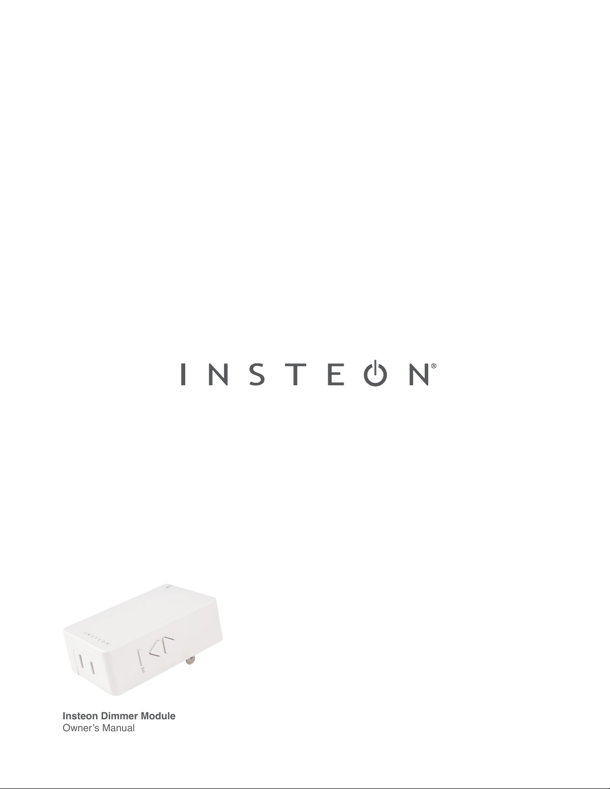
Insteon Dimmer Module
Owner’s Manual
Insteon Dimmer Module
Owner’s Manual

Contents
Getting Started
Insteon Dimmer Module 4
Device Overview
Buttons
Installation
Leave Your Lamp On
Insteon Links
Understanding Linking 6
Links are One-Way
Links Remember a Device’s State
Controllers
Responders
Controller-Only 7
Responder-Only
Grouping Devices
Use Cross Linking
Insteon Hub
Linking to the Insteon Hub 9
Manual Linking
Linking with a Single-Button Controller 11
Linking with a Multi-Button Controller 12
Multi-Linking or Making a Scene 13
Unlinking from a Single-Button Controller 14
Unlinking from a Multi-Button Controller 15
Multi-Unlinking or Removing a Scene 16
Local Programming
About Local Programming 18
Load Sense 19
Hardware Reset
Factory Reset 21
Software-Only Features
Beep on Button Press 23
Disable Local Programming
Blink on Trac
Error Blink
Appendix
Specications 26
Troubleshooting 29
Certications and Warnings 31
Product Warranty 32

3
Everything you need to quickly get up and running.
Getting Started
Everything you need to quickly get up and running.
Getting Started
4
Leave Your Lamp OnInstallation
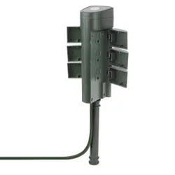
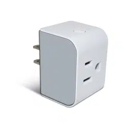
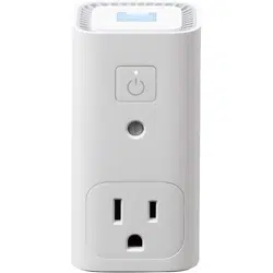
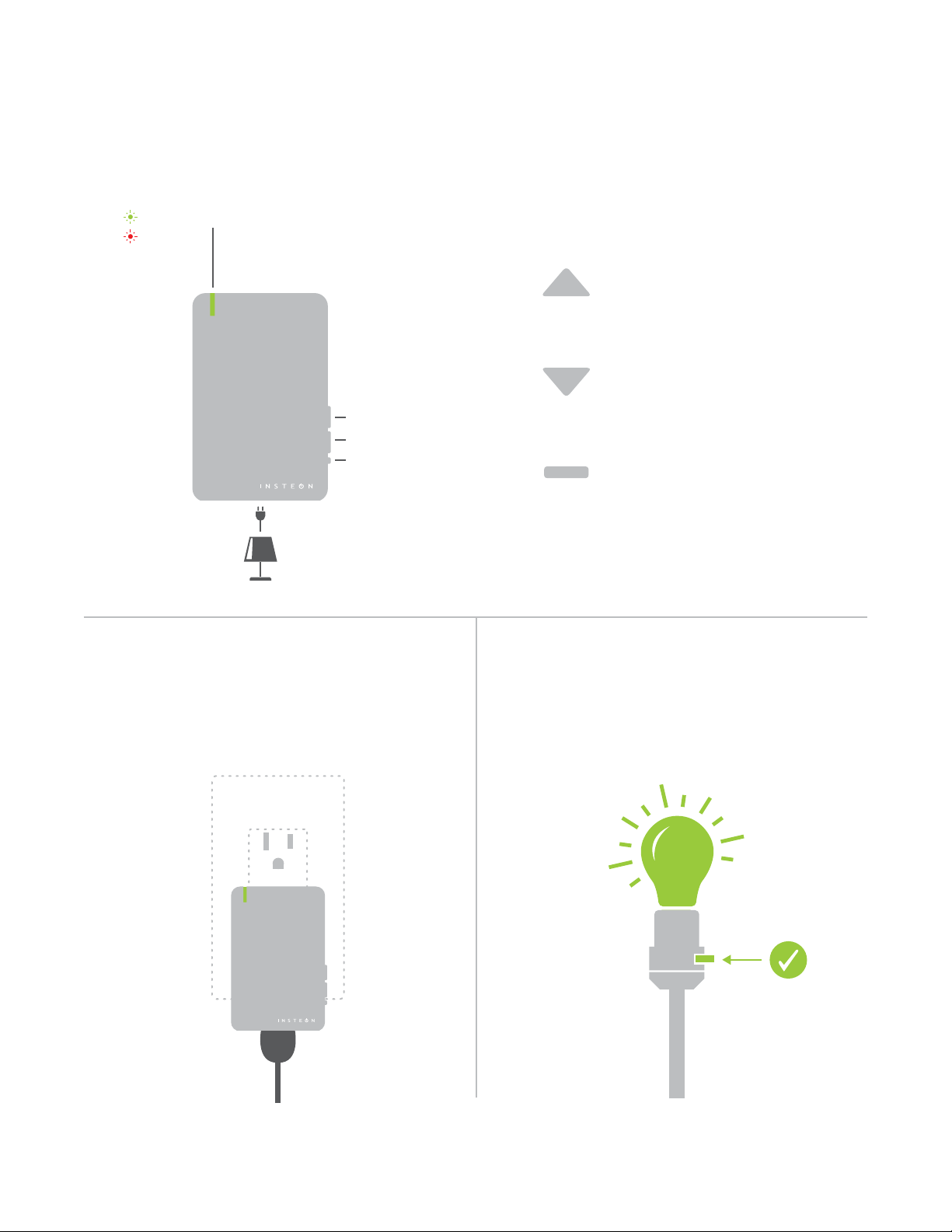
ButtonsDevice Overview
Insteon Dimmer Module
Set Button
On
O
Status LEDOn
O
®
Plug your lamp into the bottom of the
Dimmer Module and plug the Dimmer Module
into an unswitched wall outlet.
Tap to turn o
Double-tap to turn o instantly
Press and hold to dim
Tap to turn on
Double-tap to turn on instantly
Press and hold to brighten
See sections on Basic Linking and
Local Programming for set button
functions
®
If your lamp’s switch is OFF, the Dimmer Module
will be unable to remotely control your lamp.
ON
5
Insteon devices can stand alone and function as a local switch or dimmer,
but their real power comes when they are connected together to form a
control system. Most Insteon devices can control one another and be the
recipient of control. The process of associating multiple Insteon devices to
one another is called Linking.
Insteon Links
6
When linking Insteon devices, the links that
are created are one-way.
The current state of the controlled device is
stored in the link: on, o or dimmed.
Switch A will turn Switch B on and o but
Switch B cannot turn Switch A on or o.
The switch will turn on the Dimmer Module
to 75% brightness.
A SwitchB Dimmer Module
NEW
X
NEW
X
75%
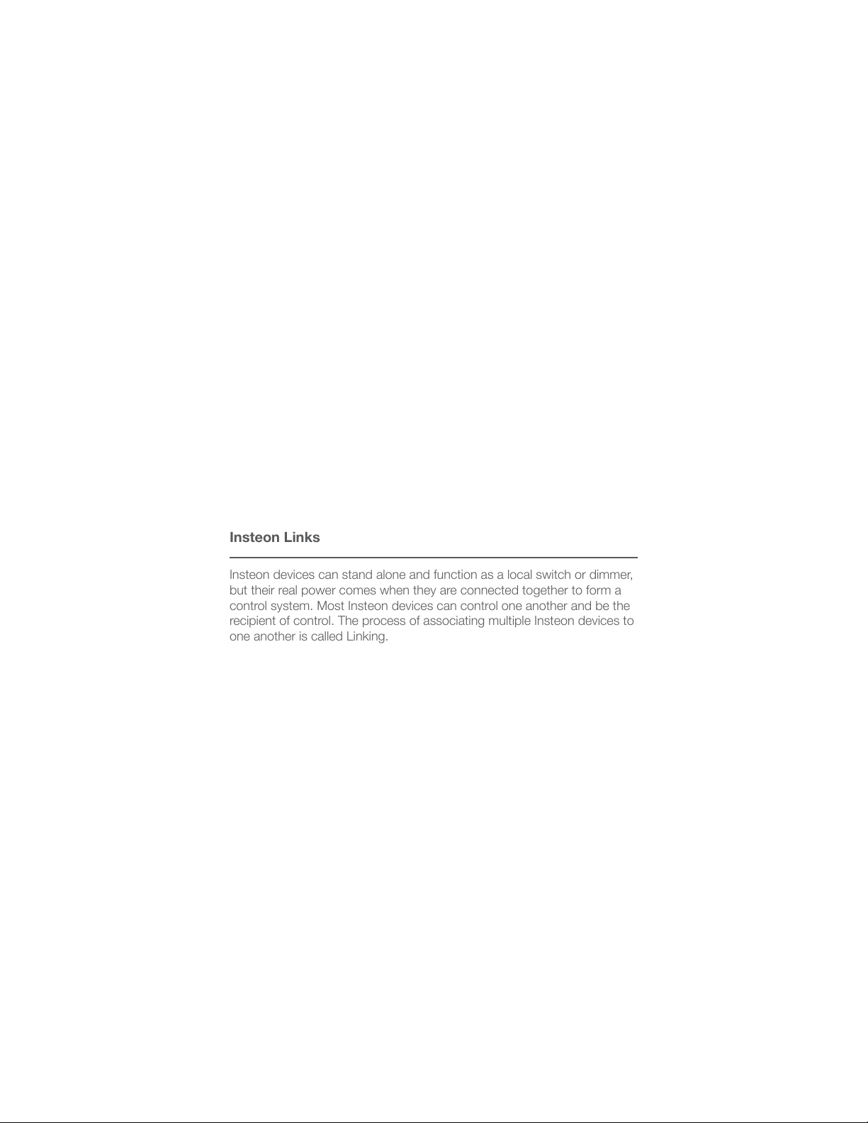
Insteon devices that can turn other devices on
or o are called controllers.
Sensors, Switches, Keypads and the
Hub are common controllers.
NEW
X
Insteon devices that receive the command of a
controller are called responders.
Switches, LED Bulbs, Plug-In Modules and
Micro Modules are common responders.
NEW
X
RespondersControllers
Links Remember a Device’s StateLinks are One-Way
Understanding Linking
Neutral
On
Off
Set
N
N
Load L1
Line L
7
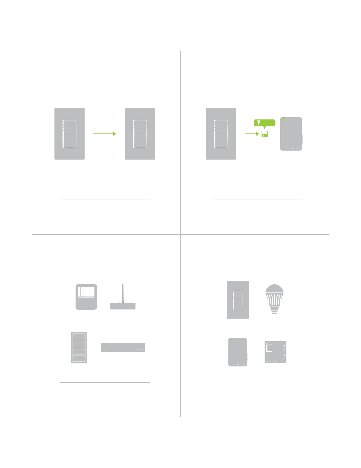
Controller-Only
Some devices like sensors can only control
other devices.
The Motion Sensor will turn on the Switch
but the switch cannot control the Motion
Sensor.
Motion Sensor
NEW
X
X
Responder-Only
Some devices cannot control other devices;
these devices only receive Insteon commands.
Some devices can only link as
responders to devices and scenes.
LED Bulb Dimmer SwitchDimmer Switch
NEW
X
X
Understanding Linking
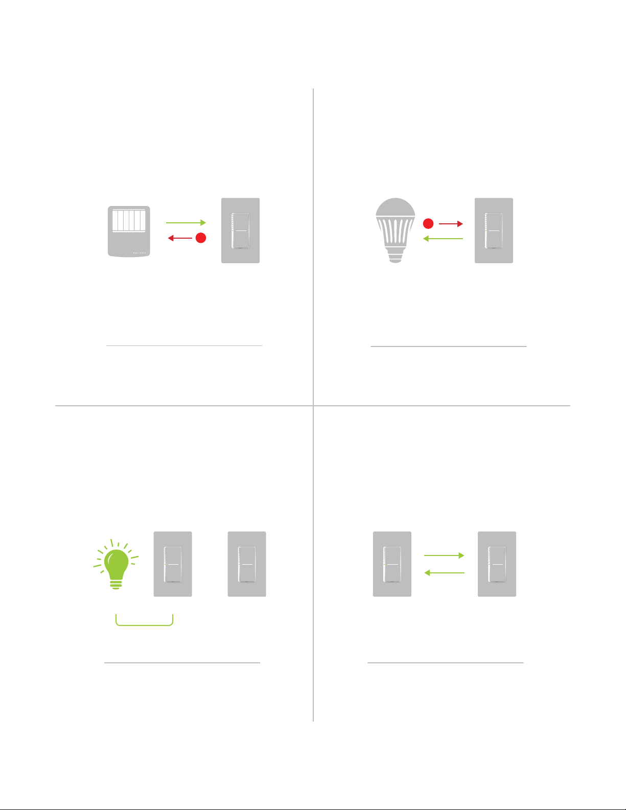
Grouping Devices Use Cross Linking
You may want to group together two
devices, for example, in a virtual-three way
conguration. For Insteon, this is called Cross
Linking.
To Cross Link, simply turn on the devices and
perform the linking process twice, once in
each direction.
To group Switch A and B so that they each
control one another and the connected
load, Cross Linking is necessary.
Link Switch A to Switch B and repeat to link
Switch B to Switch A.
NEW
X
NEW
X
A AB BLoad

8
The Insteon Hub allows you to congure your device, customize its
properties, create scenes and more, all from your smartphone or tablet.
Insteon Hub
The Insteon Hub allows you to congure your device, customize its
properties, create scenes and more, all from your smartphone or tablet.
Insteon Hub
9
You can now control your Dimmer
Module from the Insteon Hub.
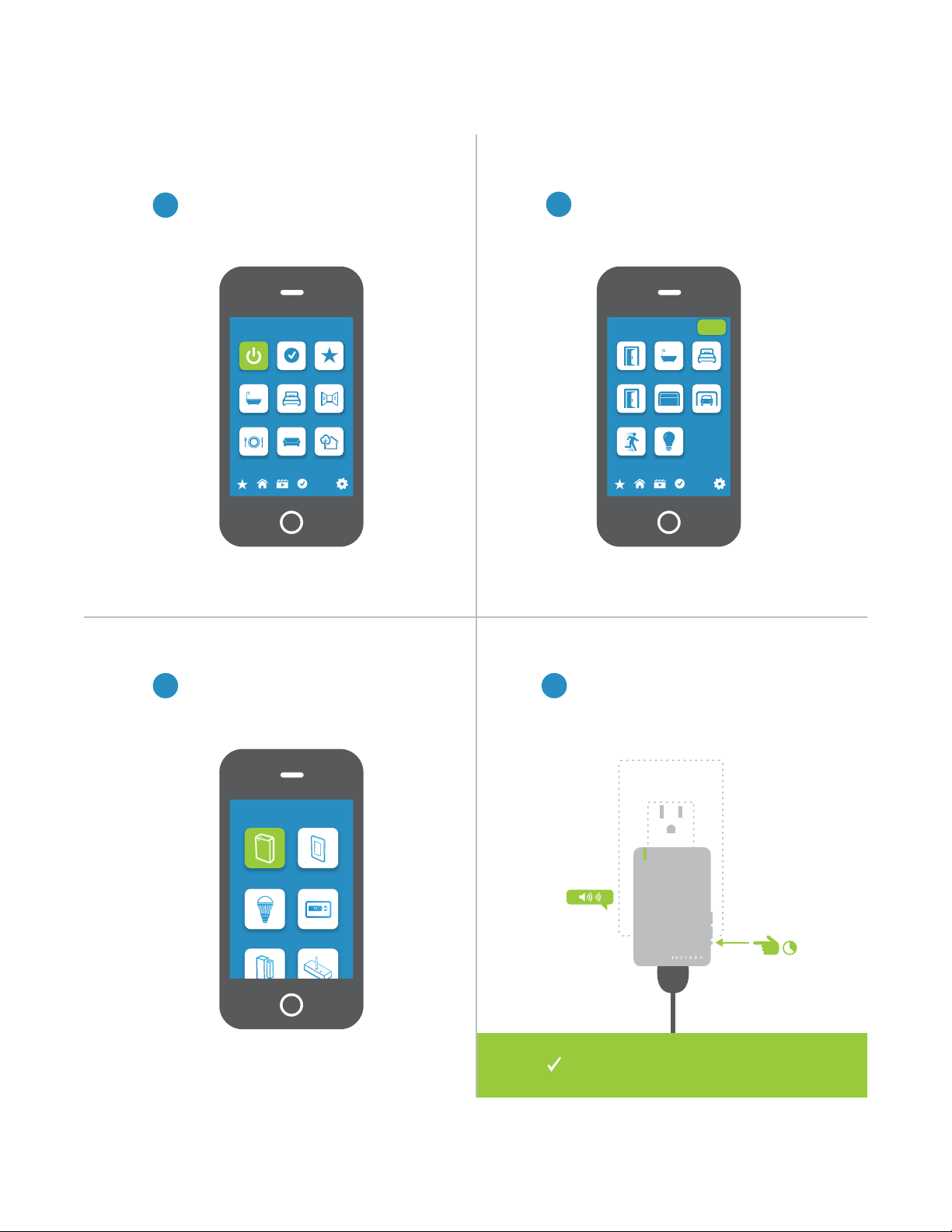
Linking to the Insteon Hub
1
4
From Rooms, navigate to All Devices.
When prompted, press and hold the
set button on your Dimmer Module
until the device double-beeps.
®
Rooms
All Devices Check-In Favorites
Bathroom Bedroom Hallway
Kitchen Living Room Outside
72º
Add Device
Plug-In Module Wired In
LED Bulb Thermostat
3
Select Plug-In Module form the list of
devices.
2
Tap the Add button.
All Devices
Back Door Bathroom Bedroom
Font Door Garage Door Garage Light
Motion Sensor Outside Lights
72º
Add
10
When not using a central controller like the Insteon Hub, Insteon devices
can be congured and linked manually on a device-to-device basis. It is
strongly advised that you not perform manual linking when using a central
controller. Instead, let your central controller handle the linking for you.
Manual Linking
11
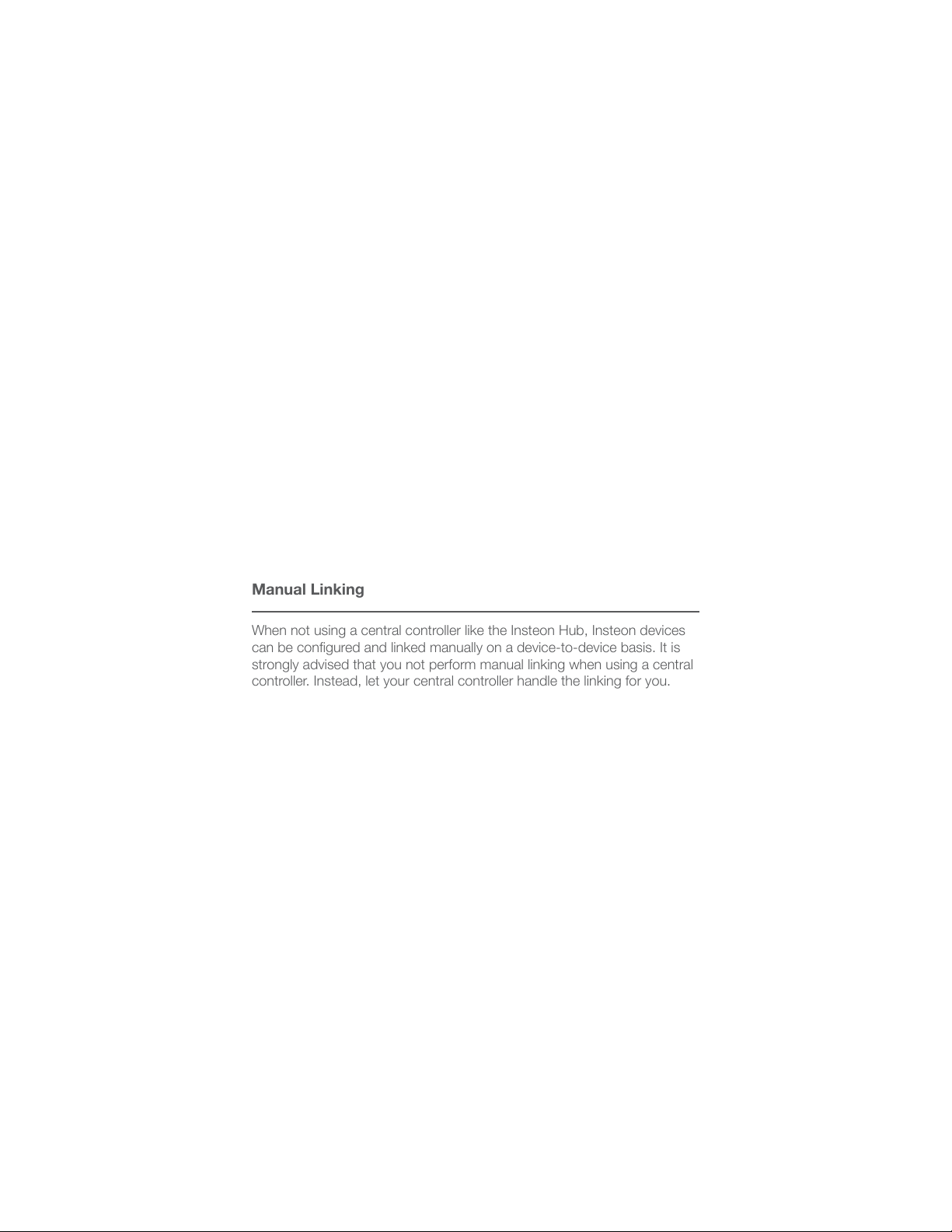
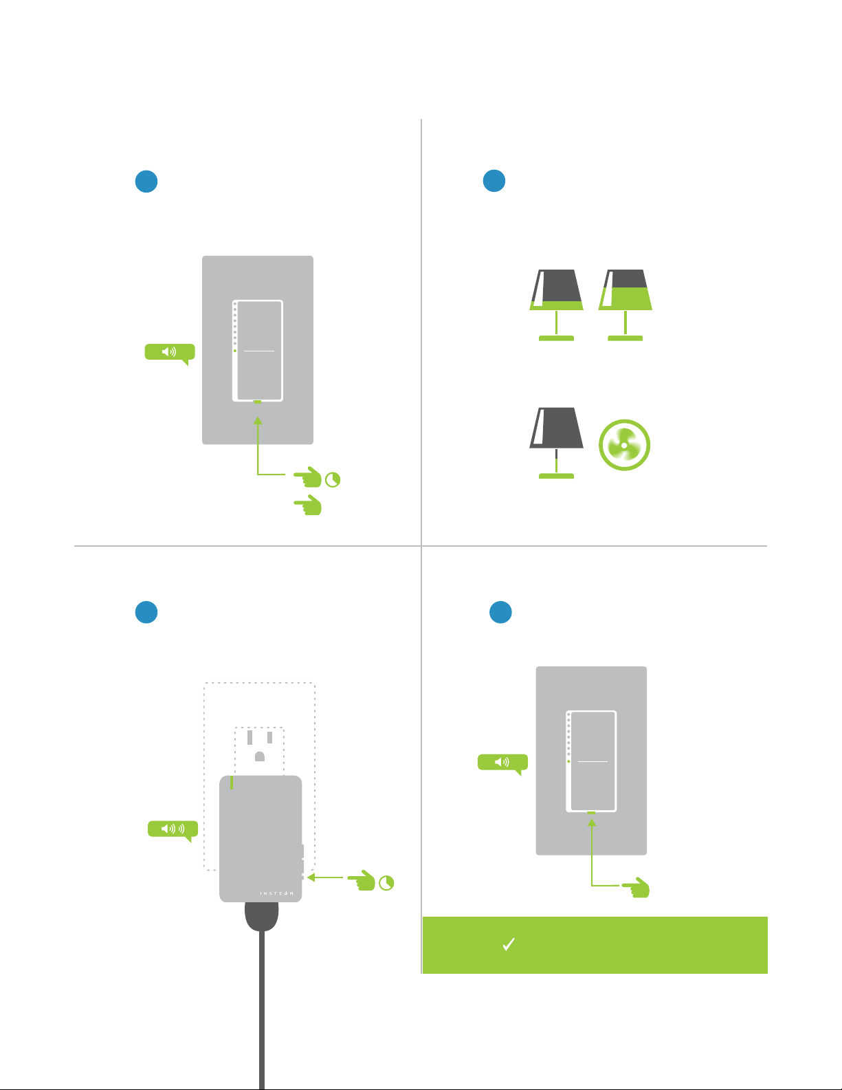
Linking with a Single-Button Controller
2
Make sure the Dimmer Module is
On and then press and hold the
Dimmer Module’s set button until
the device double-beeps.
1
On your Insteon controller, press
and hold the set button until the
device beeps.
Manual Linking Only
®
®
Your Insteon controller will now
control your Dimmer Module.
12
A
B
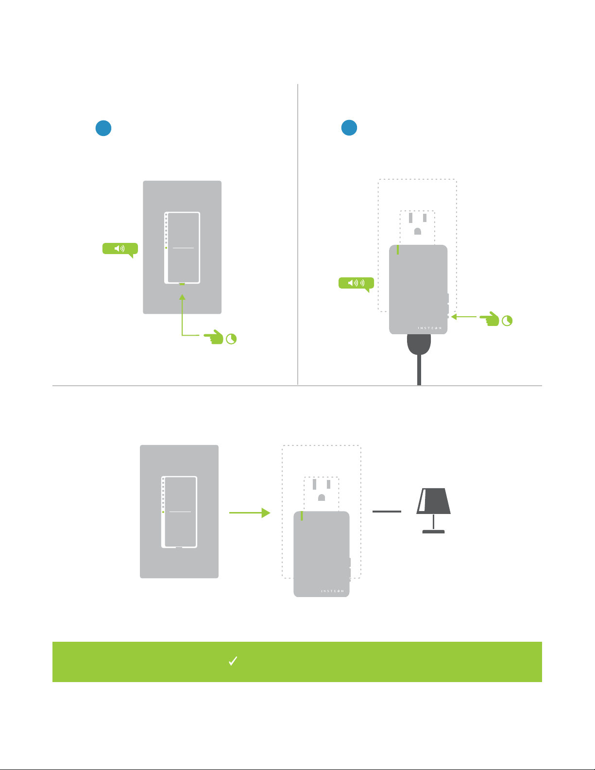
Linking with a Multi-Button Controller
2
Make sure the Dimmer Module is
On and then press and hold the
Dimmer Module’s set button until
the device double-beeps.
1
On your Insteon controller, tap the
desired control button and then
press and hold the set button until
the device beeps.
®
®
Your Insteon controller will now
control your Dimmer Module.
Manual Linking Only
13
Multi-Linking or Making a Scene
2
3 4
Adjust your scene members to
their desired state: on, o, or
brightness level if dimming.
Lamp 1
Lamp 3
Lamp 2
Appliance
One at a time, press and hold the
set button on each scene member
until it double-beeps.
Tap the set button on your Insteon
controller to nish building your
scene.
1
On your Insteon controller, press
and hold the set button until the
device beeps, then tap the set
button.
50% 72%
30%
ON
®
A
B
Your Insteon controller will now
control your scene.
Manual Linking Only
14
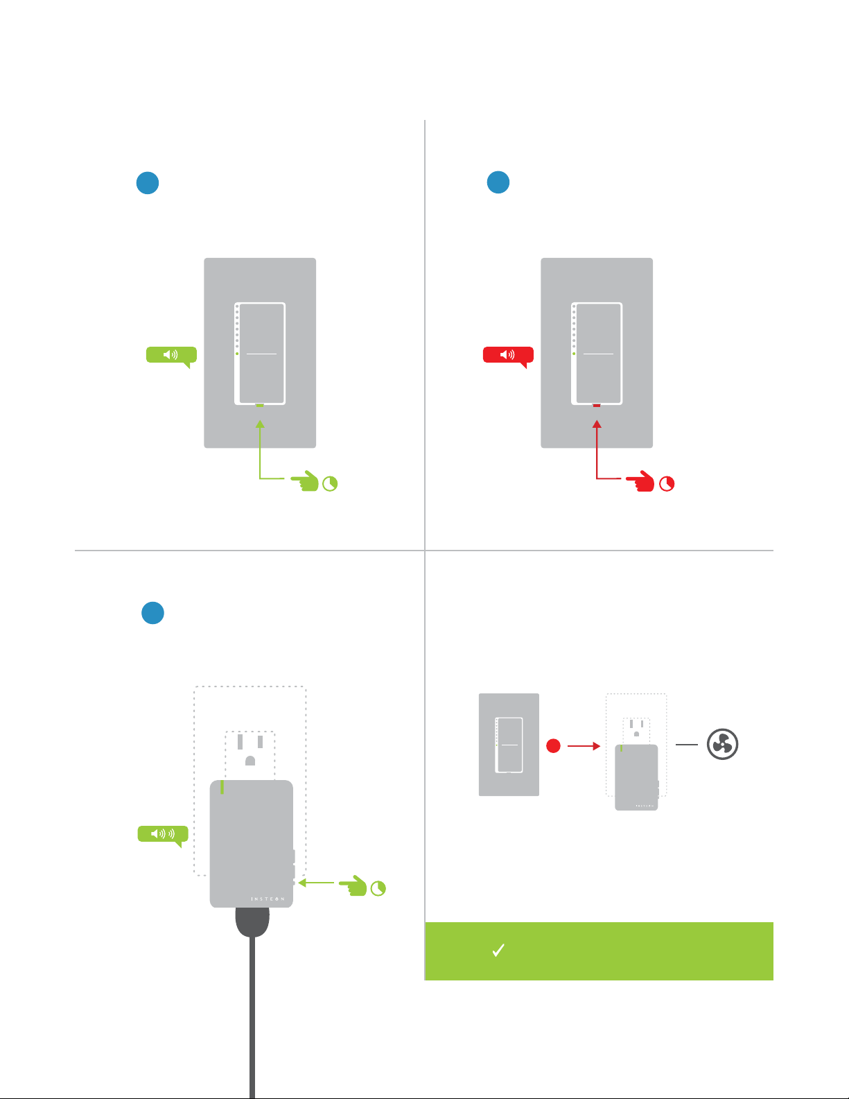
Unlinking from a Single-Button Controller
1
On your Insteon controller, press
and hold the set button until the
device beeps.
2
Press and hold the set button
again until the device beeps.
3
Press and hold the Dimmer
Module’s set button until the
device double-beeps.
®
®
X
Your Insteon controller will no longer
control your Dimmer Module.
Manual Linking Only
15
A
B
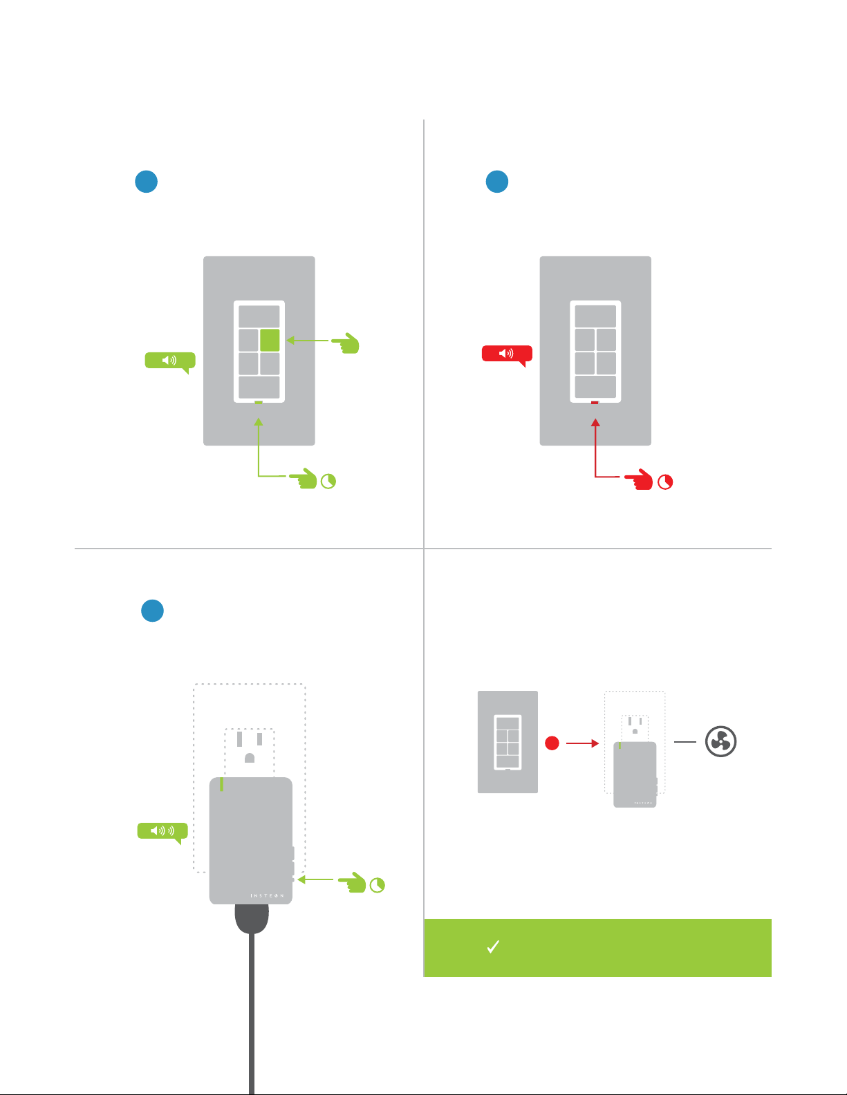
1
On your Insteon controller, tap the
desired control button and then
press and hold the set button until
the device beeps.
Unlinking from a Multi-Button Controller
2
Press and hold the set button
again until the device beeps.
3
Press and hold the Dimmer
Module’s set button until the
device double-beeps.
®
®
X
Your Insteon controller will no
longer control your Dimmer Module.
Manual Linking Only
16
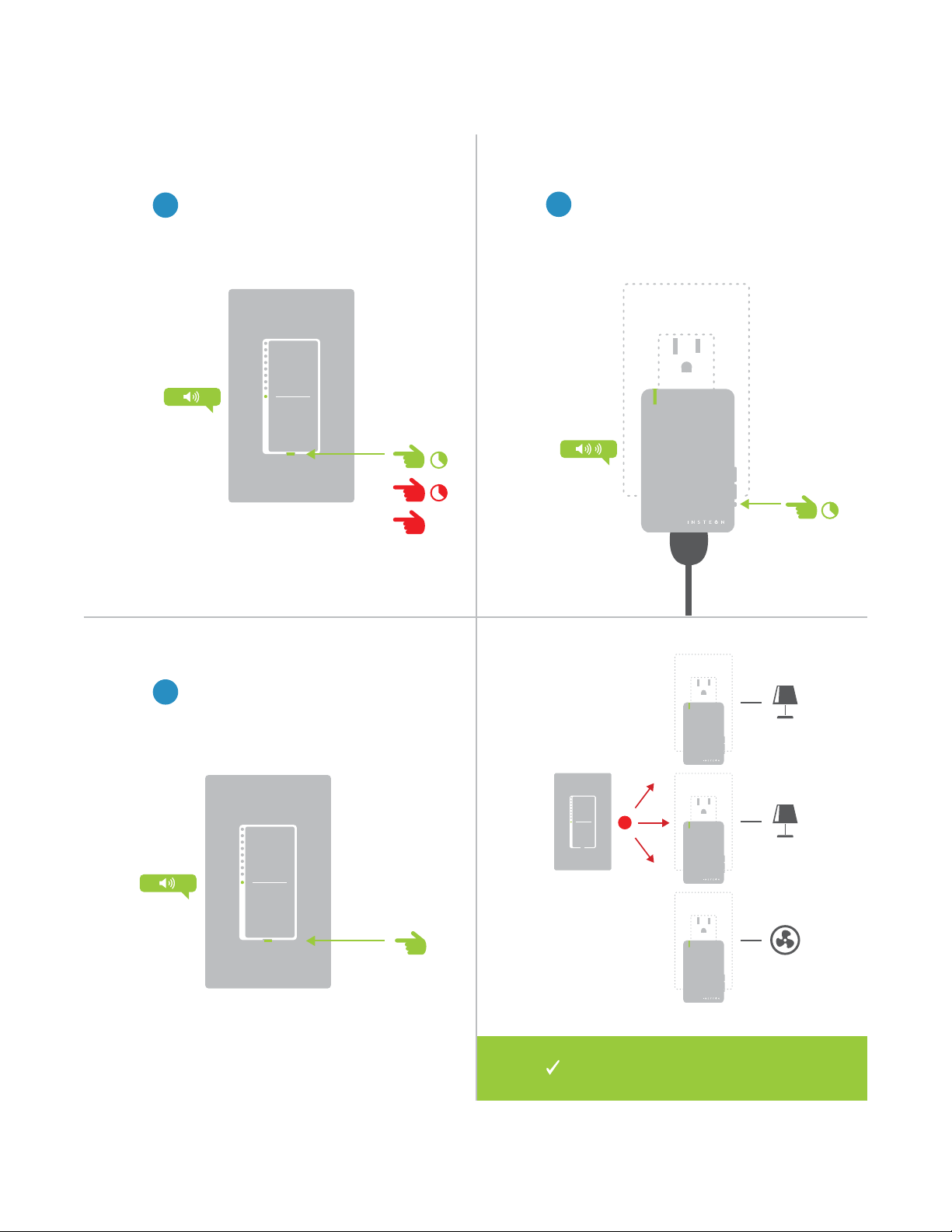
Multi-Unlinking or Removing a Scene
2
3
One at a time, press and hold the
set button on each scene member
until it double-beeps.
Tap the set button on your Insteon
controller to exit Multi-Unlinking
mode.
1
On your Insteon controller, press
and hold the set button until the
device beeps. Press and hold the
set button again, then tap the set
button.
®
A
B
C
®
®
®
X
Your Insteon controller will no longer
control your Insteon responders.
Manual Linking Only

17
Use the local programming to set local on-level, ramp rates and even
perform a factory reset.
Local Programming
Use local programming to set local on-level, ramp rates and even perform
a factory reset.
Local Programming
18
About Local Programming
Local Programming Features
Linking Mode Readies the module for linking to another Insteon device. As linking is directional, the rst device placed
into linking mode will become the controller in the controller/responder relationship. The second device will
become the responder. The device automatically exits linking mode after a link has been made with another
Insteon device or four minutes have elapsed without linking.
Multi-Linking
Mode
Readies the module for linking to multiple Insteon devices. The module will remain in linking mode for 4
minutes or until the module’s set button is tapped. This mode is very usefully for manually creating scenes.
Unlinking
Mode
Allows the removal of links from the Insteon device. The device will automatically exit unlinking mode after a
link has been removed from another Insteon device or four minutes have elapsed without linking.
Multi-
Unlinking
Mode
Allows the removal of multiple links from the Insteon device. The device will stay in unlinking mode for 4
minutes or until the device’s set button is tapped.
LED
Brightness
Allows adjusting the brightness level of the module’s status LED.
RF Beacon Places the device in a mode that broadcasts a signal over Insteon RF. Any devices beeping or displaying a
blinking LED are within range of the module’s RF signal.
Factory Reset Erases any user-customized programming from the device including all Insteon device links, scenes, ramp
rate, on-level, etc. A factory reset cannot be undone.
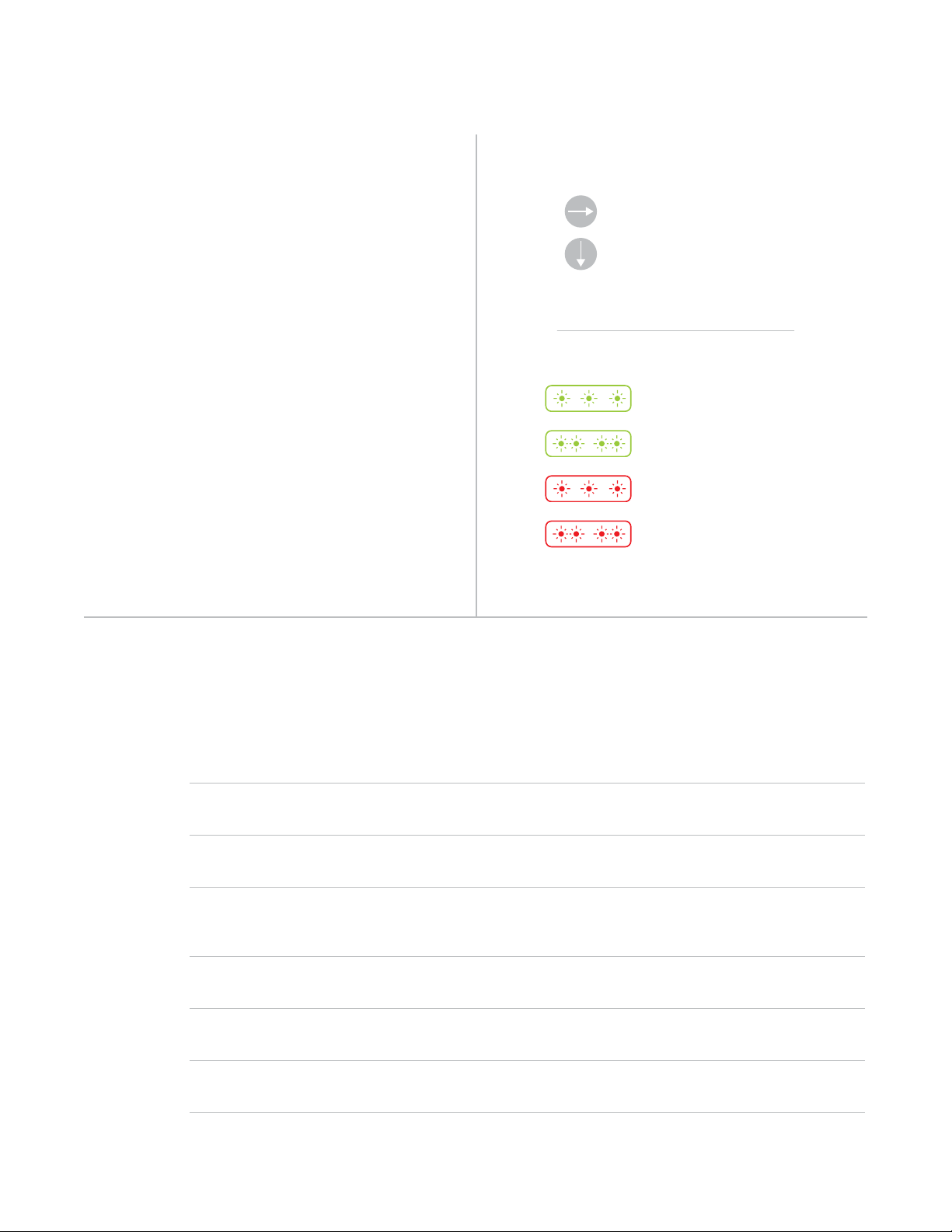
To move right, press and
hold the set button
To move down, tap the set
button
Status LED blinks green
Status LED double-blinks
green
Status LED blinks red
Status LED double-blinks
red
The Local Programming Flowchart is a visual
representation of the device’s settings. Many
device features can be congured using this
diagram. Some devices have more options
than others but the Local Programming
Flowchart presents even the most
complicated devices with a straightforward,
navigable path.
If using the Insteon Hub or any other central
controller, it is strongly advised that you
not use Local Programming. Your central
controller can manage the device properties
and links for you.
Navigation Local Programming
Using a Central Controller
NEW
X
19
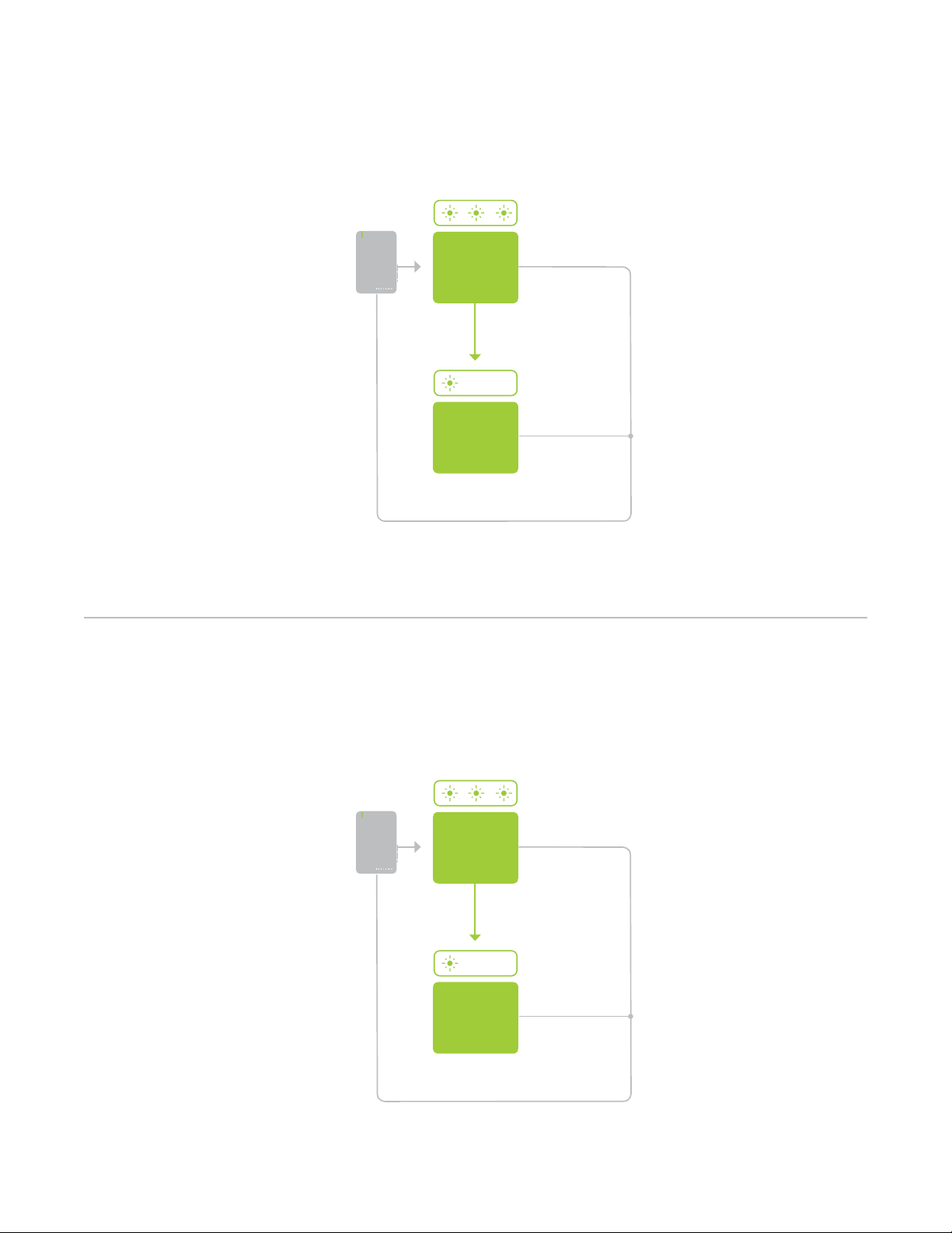
Load Sense
Load Sense
Linking Mode
Linking Mode
Disable
Load Sense
SOLID
Enable
Load Sense
SOLID
Press
Press
Tap 2x Tap 3x
Exit
Exit
Disable
Enable
20
Chapter explanation
Chapter Title
A factory reset will erase all links stored in the device’s database as well as
any customized properties.
Hardware Reset
A factory reset will erase all links stored in the device’s database as well as
any customized properties.
Hardware Reset
21
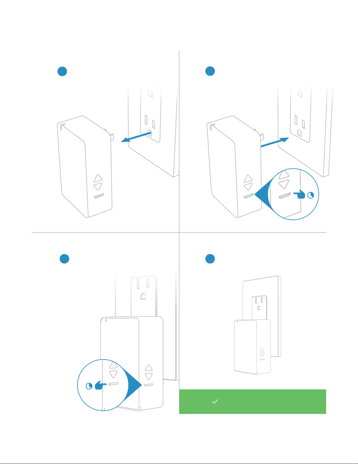
Your Dimmer Module has been
restored to factory settings.
Factory Reset
1
Unplug Dimmer Module from its
power outlet.
2
Simultaneously press and hold
the set button while reconnecting
Dimmer Module to power.
3
Continue holding the set button
until Dimmer Module stops
beeping
4
When the reset is complete,
Dimmer Module will double-beep
22
Most Insteon devices contain features that can only be enabled, disabled
or modied using Insteon control software such as HouseLinc and an
Insteon PowerLine Modem or the Insteon Hub.
Software-Only Features
Most Insteon devices contain features that can only be enabled, disabled
or modied using Insteon control software such as HouseLinc and an
Insteon PowerLine Modem or the Insteon Hub.
Software-Only Features
23
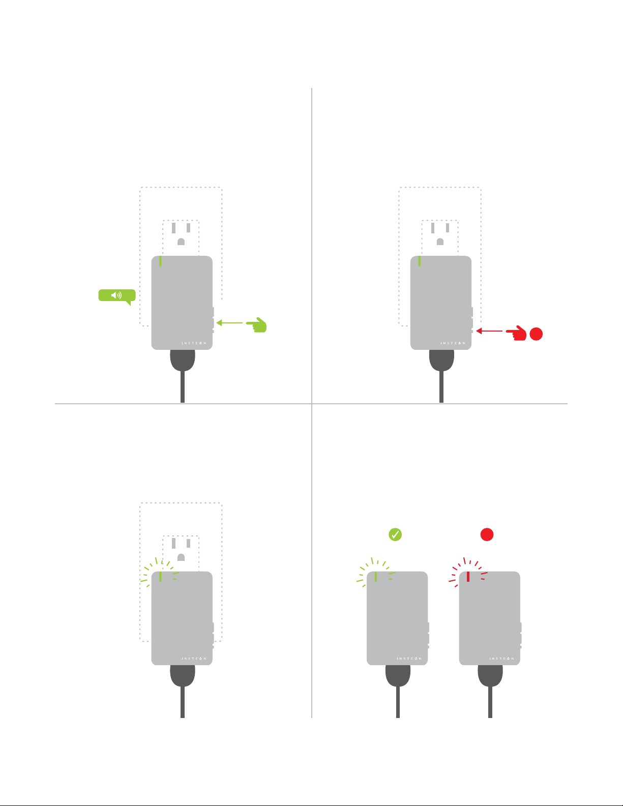
Software-Only Features
Beep on Button Press Disable Local Programming
Blink on Trac Error Blink
The Dimmer Module will beep every time one
of its buttons are tapped. By default, this
feature is disabled.
Prevents changing any settings using the
set button or tap-and-hold programming. By
default, this feature is disabled.
The Dimmer Module LED will blink if it detects
Insteon communication. By default, this
feature is disabled.
The Dimmer Module LED will blink red once if
one or more responders do not acknowledge
a message and will blink green once if all
responders successfully acknowledge a
message. By default, this feature is enabled.
®
®® ®
®
X
X

24
Everything else you might need to know about your Insteon product.
Appendix
Everything else you might need to know about your Insteon product.
Appendix

25
Insteon Glossary
Controller The Insteon transmitter
Responder The Insteon receiver
Blinking LED turning on and o repeatedly
Dual-Band An Insteon device that can send and receive both Insteon powerline signals and Insteon
radio frequency signals
Ramp Rate The speed at which the load fades on or o
On-Level The preset brightness level a device will return to when turned on
Insteon A dual-band, mesh networking technology developed by Smarthome/Insteon. The world’s
most reliable, expandable and simple home automation and control technology.
Link A one way association between a controller and responder
Linking A method for associating Insteon controller buttons with groups of Insteon responders such
that the responders instantly return to a memorized state when the button is pushed. Links
can be made manually with the set button or using software.
Unlinking The process by which an Insteon device can remove stored links. Just as with linking,
unlinking is a one-way process and should be performed in both directions for devices that
are both controllers and responders of each other, as in a 3-way switch scenario.
Multi-Linking
/ Unlinking
A special mode that allows more than one link to be either created or removed
simultaneously, without laborious set button presses. When in linking or unlinking mode,
an Insteon device will continue to link to other devices until the set button is tapped or four
minutes have elapsed, whichever occurs rst.
Factory Reset A process that erases all stored links and recongures the device to factory defaults.
Load The device that you are controlling (e.g. a light bulb, ceiling fan, etc.)
On/O A device that can control its connected load to turn on and o but cannot dim. Usually a
relay-based device.
Retry A 2nd (or subsequent) attempt by a controller to send an Insteon signal, usually after an
acknowledge is not received from the responder in the expected time-slot.
Scene Multiple devices respond to memorized states. For example, a dinner time scene turns
on the dining table light, dims the kitchen lights to 10%, backyard lights turn o and the
thermostat adjusts to 72º.
Set Button A button on an Insteon device that is used for setting or changing its properties
Simulcast A method for increasing the reliability of message delivery in a network. When a node in
a network sends a message, every other node that hears the message retransmits it at
precisely the same time based on a global clock, provided that the message has not already
been retransmitted some maximum number of times. Message propagation is more robust
because each node adds its energy to the signal, much like voices in a choir. Simulcasting
is much simpler than message routing because there are no routing tables to maintain and
nodes can join the network without any installation procedure.
X10 A legacy powerline networking technology. Many Insteon devices are backwards compatible
with X10 devices by setting a house and unit code.

26
Specications
General
Available Colors White
Brand: Insteon
FCC ID SBP2475D2A
Industry Canada 5202A-2475D2A
Manufacturer Product No.: 2475D2
Patent No.: Protected under US and Foreign Patents (see www.insteon.com/
patents)
UPC: 813922010183
Warranty: 2 years, limited
Operation
Audio Alert Beeper, can be enabled/disabled through software
Operation Modes Insteon. Versions prior to 3.6 also support X10.
Load Sensing Yes. Versions prior to 3.6 do not support load sense.
Local Control Yes
Setup Memory Non-volatile EEPROM
Status LED Red/Green LED
Insteon Features
Insteon Device Category 0x01 dimmable lighting control
Insteon Device Subcategory 0x37
Insteon ID 1
Insteon Links 400
Insteon Messages Repeated Yes
Insteon Minimum Receive Level 10 mV
Insteon Minimum Transmit Level 3.2 Vpp into 5 Ohms
Insteon Powerline Device Yes
Insteon Powerline Frequency 131.65 KHz
Insteon RF Device Yes
Maximum Controlled Scenes 1

27
Maximum Scene Memberships 400
Multi-Link Support Yes
Multi-Unlink Support Yes
RF Beacon Yes
Radio Frequency 915.0 MHz
Radio Frequency Range 150 feet
Scene Commands Supported as
Controller
On O
Fast-On Fast-O
Begin Brighten Begin Dim
End Brighten End Dim
Scene Commands Supported as
Responder
On O
Fast-On Fast-O
Begin Brighten Begin Dim
End Brighten End Dim
Beep
Software Congurable Yes
Mechanical
Dimensions 3.2” H x 2.05” W x 1.05” D
81.2mm H x 53mm W x 26.6mm D
Dimming Technology Employed Leading-edge TRIAC dimmer
Enclosure Material UV stabilized plastic
Mounting Ungrounded, polarized electrical outlet, NEMA 1-15
Operating Environment Indoors
Operating Humidity Range 0-85% relative humidity, non-condensing
Operating Temperature Range 32º to 104º F
0º to 40º C
Set Button Yes
Storage Temperature Range -4º to 158º F
-20º to 70º C
Weight 3.3 oz

28
Electrical
Controlled Outlet Yes, ungrounded polarized. NEMA 1-15 type
Hardwired Remote Control No
Load Types Plug-in incandescent lighting sources
Maximum Load 300 Watts
Minimum Load 5 Watts
Pass-through Outlet No
Power Consumption <0.75 Watts
Supply Voltage 120 Volts AC ± 10%, 60 Hertz, single phase
Surge Resistance Surges over 1,000 volts
X10 Features (Powerline Only)
X10 Support No. Versions prior to 3.6 support X10.

29
Troubleshooting
Dimmer Module LED does not turn on
It is possible your Dimmer Module is not receiving power. If the attached load can still be controlled, It is possible
that the status LED has been disabled.
Try this:
• Test Dimmer Module in a dierent power outlet. If the LED illuminates when using a dierent outlet, check
the original outlet for power. Some outlets are controlled by a switch elsewhere in the room. Avoid switched
outlets as they disable your Insteon device when turned o.
• If the outlet works and the connected lamp can be toggled, use software or the Local Programming
Flowchart to change the behavior of the status LED. The status LED brightness can be dimmed to the
point that it appears o. The Insteon Hub and other central controller software allow setting of this device
property.
Unable to add Dimmer module to a scene as a controller or a responder
If the device has power, something is likely interfering with the Insteon signal. Large appliances, power strips and
some electronic devices may generate powerline noise.
Try this:
• Check to see if you have connected Dimmer Module to a power strip, surge suppressor, backup battery or
AC line lter. These devices often lter out the Insteon powerline signal. Relocate the Dimmer Module to a
standard AC outlet.
• Large appliances like refrigerators or air conditioners may be generating powerline noise that is disrupting
the Insteon signal. If the issue only appears to happen when one of these large appliances is running, install
a noise lter at that device. If you are uncertain of the device generating the noise, disconnect the potentially
oending devices from power and test your Dimmer Module again. If the issue is resolved, install noise
lters at each oending appliance.
• Some small electronics devices that include an AC/DC power supply can generate substantial electrical
noise, in some cases, enough to disrupt an entire house of Insteon devices. Search your home for speaker
docks, small stereos, etc. and disconnect them from power to perform testing. If removing these devices
from your powerline resolves the Insteon issue, install a noise lter at each oending small electronic
appliance.
• Your Dimmer Module may be too far from another Insteon device to receive a signal. Try locating the
Dimmer Module closer to another Insteon device and if the issue is resolved, install a Range Extender
or other Dual-Band Insteon device between the intended location of your Dimmer Module and the next
nearest Insteon device.
The Dimmer Module is slow to respond to commands from a controller
This issue most likely lies with the controller, not the Dimmer Module; the controller is most likely repeating
commands not acknowledged by an Insteon device that has been removed from the network. The repeated
commands are slowing down the Insteon network, resulting in a delayed response from the Dimmer Module.
Try this:
• Consider if you have removed any Insteon devices from you network that were part of the slow-to-respond
scene. If so, the links to these devices need to be removed from the controller. Use software to examine the
database of the controller or if you know the modules that were removed, manually remove their links using
the standard unlinking procedure.
• If you are unable to identify the missing devices, perform a factory reset on the controller. This will remove
all links from the controller’s database but will also require that you recongure the device’s scenes and
properties.

30
Troubleshooting
The connected lamp turned on by itself
There must be a device in your Insteon network that is unexpectedly linked to the Dimmer Module. If you have
given your device an X10 address, powerline noise may be triggering the Insteon device.
Try this:
• Use software to examine the Dimmer Module’s links. If you can identify the stray controller, remove the link.
• If you are unable to identify the unexpected controller, perform a factory reset on the Dimmer Module.
This will remove all links from the module’s database but will also require that you recongure the device’s
scenes and properties.
• If you have assigned your device an X10 address, try assigning a dierent X10 address or taking steps to
identify and isolate electronics that may be generating powerline noise.
Using a controller, Dimmer Module will turn o but not turn on
Most likely, the Dimmer Module was linked to the controller with the load set to O
Try this:
• Make sure the Dimmer Module’s connected load is on and then re-link the device to your Insteon controller.
This link will overwrite the previous “o” link.
Dimmer Module does not respond to button taps or controller links
A power surge or excessive powerline noise may have caused the module to unexpectedly stop responding.
Try this:
• Unplug Dimmer Module for 10 seconds and then reconnect the device to power. Test the local buttons to
see if the load will turn on or o.
• While unusual, Dimmer Module may require a factory reset to restore normal operation. Follow the
procedure outlined in Local Programming to reset the device to factory settings. You will be required to
recongure the device’s scenes and properties after the reset.
When using the connected lamp’s switch, the load does not turn on
Your load may not be receiving power if the Dimmer Module is o.
Try this:
• Use the buttons on the side of the Dimmer Module to turn on the connected device. Remember, if the
connected lamp is turned o using its own switch, Dimmer Module is unable to control the device.
• Check the bulb in your lamp. It is possible that your light bulb needs to be replaced.

31
Certications and Warnings
Read and understand these instructions before installing and retain them for future reference.
This product is not designed or approved for use on powerlines other than 120VAC, 50Hz or 60Hz, single
phase. Attempting to use this product on unapproved powerlines may have hazardous consequences.
• Use only indoors or in outdoor rated box
• This product may feel warm during operation. The amount of heat generated is within approved limits and
poses no hazards. To minimize heat buildup, ensure the area surrounding this product is as clear of clutter
as possible.
• Each Insteon product is assigned a unique Insteon I.D., which is printed on the product’s label.
• To reduce the risk of overheating and possible damage to other equipment, do not use this product to
control loads in excess of the specied maximum(s) or, install in locations with electricity specications
which are outside of the product’s specications. If this device supports dimming, please note that dimming
an inductive load, such as a fan or transformer, could cause damage to the dimmer, the load bearing
device, or both. If the manufacturer of the load device does not recommend dimming, use a non-dimming
Insteon device. USER ASSUMES ALL RISKS ASSOCIATED WITH DIMMING AN INDUCTIVE LOAD.
This device complies with FCC Rules and Industry Canada license-exempt RSS standard(s). Operation is
subject to the following two conditions: (1) this device may not cause harmful interference, and (2) this device
must accept any interference, including interference that may cause undesired operation of the device.
Le present appareil est conforme aux CNR d’Industrie Canada applicables aux appareils radio exempts
de licence. L’exploitation est autorise aux deux conditions suivantes: (1) l’appareil ne doit pas produire de
brouillage, et (2) l’utilisateur de l’appareil doit accepter tout brouillage radiolectrique subi, mme si le brouillage est
susceptible d’en compromettre le fonctionnement.
CAUTION - To reduce the risk of overheating and possible damage to other equipment do not install to control
a receptacle, a motor-operated appliance, a uorescent lighting xture, or a transformer-supplied appliance.
Gradateurs commandant une lampe a lament de tungstene – an de reduire le risqué de surchaue et la
possibilite d’endommagement a d’autres materiels, ne pas installer pour commader une prise, un appareil a
moteur, une lampe uorescente ou un appareil alimente par un transformateur.
The digital circuitry of this device has been tested and found to comply with the limits for a Class B digital
device, pursuant to Part 15B of the FCC Rules. These limits are designed to provide reasonable protection
against harmful interference in residential installations. This equipment generates, uses, and can radiate
radio frequency energy and, if not installed and used in accordance with the instructions, may cause harmful
interference to radio and television reception. However, there is no guarantee that interference will not occur in
a particular installation. If this device does cause such interference, which can be veried by turning the device
o and on, the user is encouraged to eliminate the interference by one or more of the following measures: •
Re-orient or relocate the receiving antenna of the device experiencing the interference • Increase the distance
between this device and the receiver • Connect the device to an AC outlet on a circuit dierent from the one that
supplies power to the receiver • Consult the dealer or an experienced radio/TV technician.
WARNING: Changes or modications to this device not expressly approved by the party responsible for
compliance could void the user’s authority to operate the equipment.
Cet appareil a été testé et s’avère conforme aux restrictions relatives aux équipements numériques de classe B,
d’après l’article 15 des règlements du Conseil supérieur de l’audiovisuel américain (FCC). Ces restrictions ont
été instaurées pour orir une protection raisonnable contre les interférences nuisibles au sein d’une installation
résidentielle. Cet appareil génère, utilise et peut émettre des fréquences radio et s’il n’est pas installé selon les
instructions, peut nuire aux radiocommunications. Toutefois, rien ne garantit que des parasites ne surviendront
pas dans une installation particulière. Si cet appareil cause des interférences nuisibles à la réception du
téléviseur ou de la radio, ce que vous pouvez déterminer en ouvrant et en fermant votre appareil, nous vous
invitons à essayer l’une des mesures correctives suivantes : • Réorientez l’antenne de réception installée sur
l’appareil qui manifeste les parasites.
• Éloignez l’appareil du composant qui reçoit les ondes. • Branchez l’appareil dans une prise de courant CA
diérente de celle du composant qui reçoit les ondes. • Au besoin, consultez votre marchand électronique ou un
technicien spécialisé dans le service des radios/téléviseurs pour des suggestions supplémentaires.

32
Product Warranty
Limited Warranty
Seller warrants to the original consumer purchaser of this product that, for a period of two years from the date
of purchase, this product will be free from defects in material and workmanship and will perform in substantial
conformity to the description of the product in this Owner’s Manual. This warranty shall not apply to defects or
errors caused by misuse or neglect. If the product is found to be defective in material or workmanship, or if the
product does not perform as warranted above during the warranty period, Seller will either repair it, replace it,
or refund the purchase price, at its option, upon receipt of the product at the address below, postage prepaid,
with proof of the date of purchase and an explanation of the defect or error. The repair, replacement, or refund
that is provided for above shall be the full extent of Seller’s liability with respect to this product. For repair or
replacement during the warranty period, call 866-243-8022 with the Model # and Revision # of the device to
receive an RMA# and send the product, along with all other required materials to:
Insteon
ATTN: Receiving
16542 Millikan Ave.
Irvine, CA 92606-5027
Limitations
The above warranty is in lieu of and Seller disclaims all other warranties, whether oral or written, express or
implied, including any warranty or merchantability or tness for a particular purpose. Any implied warranty,
including any warranty of merchantability or tness for a particular purpose, which may not be disclaimed
or supplanted as provided above shall be limited to the two-year of the express warranty above. No other
representation or claim of any nature by any person shall be binding upon Seller or modify the terms of the
above warranty and disclaimer.
Home automation devices have the risk of failure to operate, incorrect operation, or electrical or mechanical
tampering. For optimal use, manually verify the device state. Any home automation device should be viewed as
a convenience, but not as a sole method for controlling your home.
In no event shall Seller be liable for special, incidental, consequential, or other damages resulting from
possession or use of this device, including without limitation damage to property and, to the extent permitted by
law, personal injury, even if Seller knew or should have known of the possibility of such damages. Some states
do not allow limitations on how long an implied warranty lasts and/or the exclusion or limitation of damages, in
which case the above limitations and/or exclusions may not apply to you. You may also have other legal rights
that may vary from state to state.
Protected under U.S. and foreign patents (see www.insteon.com/patents)
© Copyright 2014 Insteon
Rev 07.18.16