
de Funktionsbeschreibung/
Montageanweisung
Steuermodul
DSM 400
en Operation/
Installation
Control module
DSM 400
M.-Nr. 09 165 650

de - Funktionsbeschreibung. . . . . . . . . . . . . . . . . . . . . . . . . . . . . . . . . . . . . . . . . 3
de - Montage. . . . . . . . . . . . . . . . . . . . . . . . . . . . . . . . . . . . . . . . . . . . . . . . . . . . . . 4
Wand-Dunstabzugshaube............................................4
Insel-Dunstabzugshaube.............................................7
Flachschirmhaube ..................................................8
Lüfterbaustein ....................................................10
Deckenlüfter......................................................11
de - Elektrischer Anschluss . . . . . . . . . . . . . . . . . . . . . . . . . . . . . . . . . . . . . . . . 13
Zusatzlichttaster ..................................................13
Potentialfreier Kontakt. .............................................15
en – Installation - Operation . . . . . . . . . . . . . . . . . . . . . . . . . . . . . . . . . . . . . . . . 18
en - Installation. . . . . . . . . . . . . . . . . . . . . . . . . . . . . . . . . . . . . . . . . . . . . . . . . . . 19
Wall mounted cooker hoods .........................................19
Island cooker hoods ...............................................22
Deflector plate cooker hoods ........................................23
Integrated cooker hoods ............................................25
Ceiling mounted cooker hood ........................................26
en - Electrical connection . . . . . . . . . . . . . . . . . . . . . . . . . . . . . . . . . . . . . . . . . . 28
Additional pushbutton light switch ....................................28
Potential free contact ..............................................30
de - Schaltplan en - Wiring diagram. . . . . . . . . . . . . . . . . . . . . . . . . . . . . . . . . 33
de - Wand-Dunstabzugshaube, Lüfterbaustein ..........................33
en - Wall mounted cooker hood, Integrated cooker hood....................33
de - Insel-Dunstabzugshaube ........................................34
en - Island cooker hood ..............................................34
de - Flachschirmhaube .............................................35
en - Deflector plate cooker hoods.......................................35
de - Deckenlüfter ..................................................36
en - Ceiling mounted cooker hood ......................................36
Inhalt/Contents
2

Das Steuermodul bietet folgende Mög
-
lichkeiten:
1. Anschluss eines Lichttasters
Darüber hinaus bietet das Steuermodul
die Möglichkeit, über einen in die Haus
-
installation integrierten Lichttaster die
Beleuchtung der Dunstabzugshaube zu
schalten.
2. Potentialfreier Anschluss
Er dient zum Steuern eines anderen
Gerätes in Abhängigkeit vom Schaltzu
-
stand des Gebläses der Dunstabzugs
-
haube.
de - Funktionsbeschreibung
3
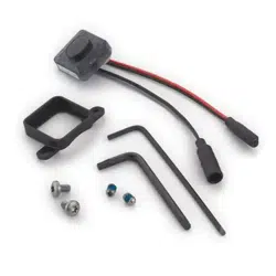
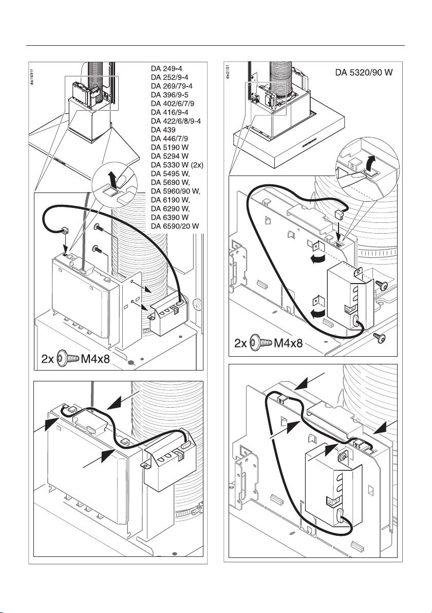
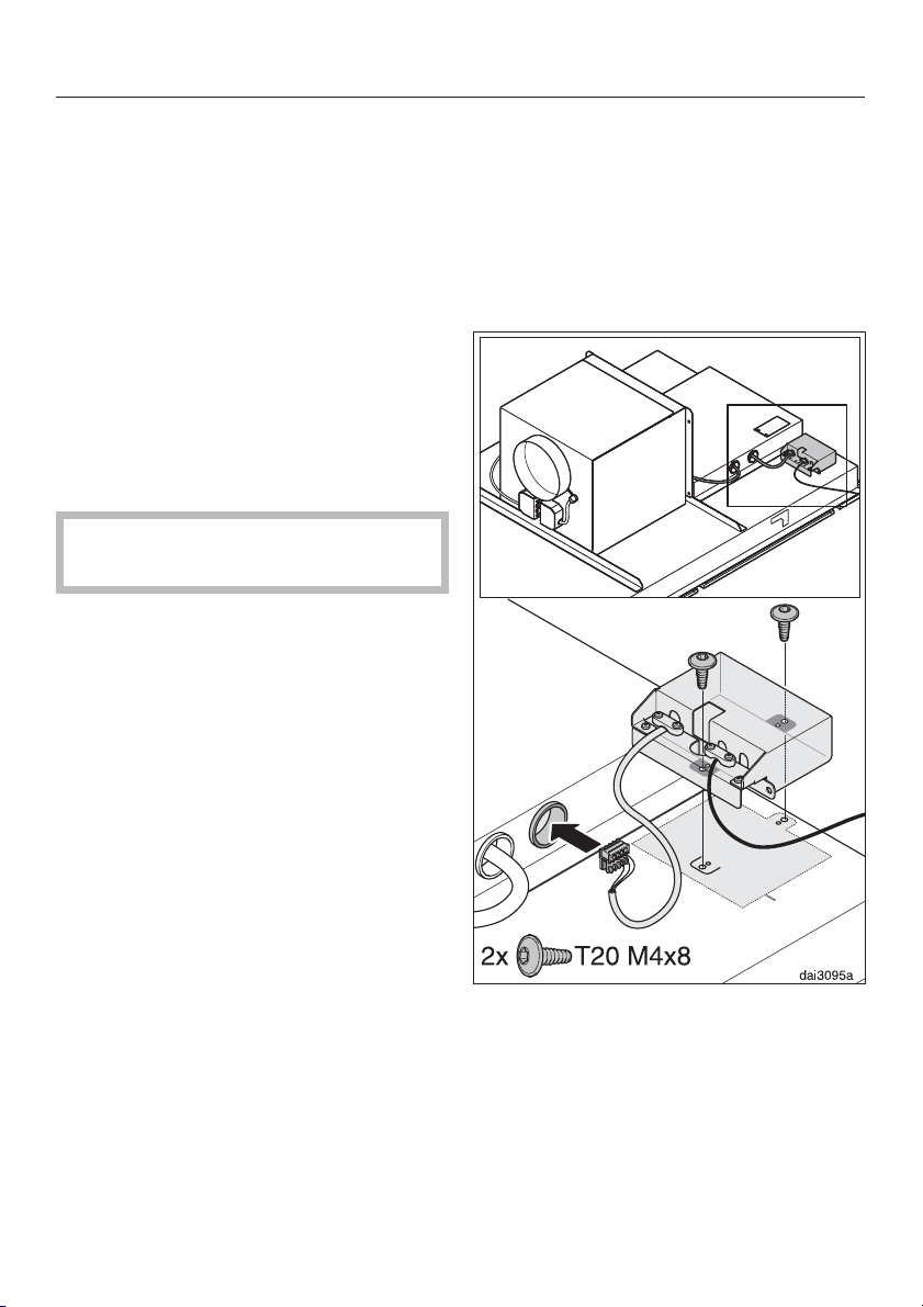
Wand-Dunstabzugshaube
DA 249-4,
DA 252/9-4,
DA 269/79-4,
DA 396/9-5
DA 402/6/7/9,
DA 416/9-4,
DA 422/6/8/9-4,
DA 439,
DA 446/7/9,
DA 5190 W,
DA 5294 W,
DA 5320/30/90 W,
DA 5495 W,
DA 5690 W,
DA 5960/90 W,
DA 6190 W,
DA 6290 W,
DA 6390 W,
DA 6590/20 W
,
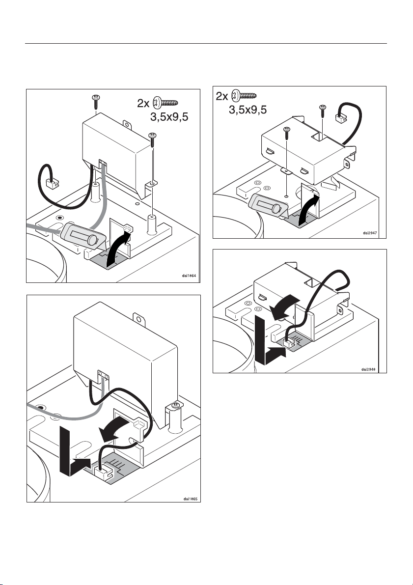
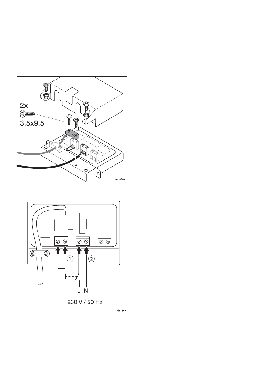
Die Dunstabzugshaube vom
Stromnetz trennen.
^
Kamin und Teleskop demontieren.
Beachten Sie dazu die Montagean
-
weisung der Dunstabzugshaube.
^
Die vorgesehenen Komponenten an
-
schließen (siehe Kapitel "Elektrischer
Anschluss" und "Schaltplan").
^
Das Steuermodul mit den beiliegen
-
den Schrauben seitlich an die Elek
-
tronikeinheit der Dunstabzugshaube
schrauben.
^ Das Anschlusskabel in die Buchse
auf der Elektronikeinheit stecken.
^ Das Kabel verlegen und in die vorge-
sehenen Halterungen stecken.
Achten Sie auf eine fachgerechte
Verlegung der Anschlussleitung und
der Leitungen der angeschlossenen
Komponenten. Sie dürfen nicht ge-
knickt oder gequetscht werden.
^
Abschließend die Dunstabzugshaube
wieder an das Stromnetz anschließen
und das Teleskop und den Kamin
wieder montieren.
de - Montage
4
de - Montage
5
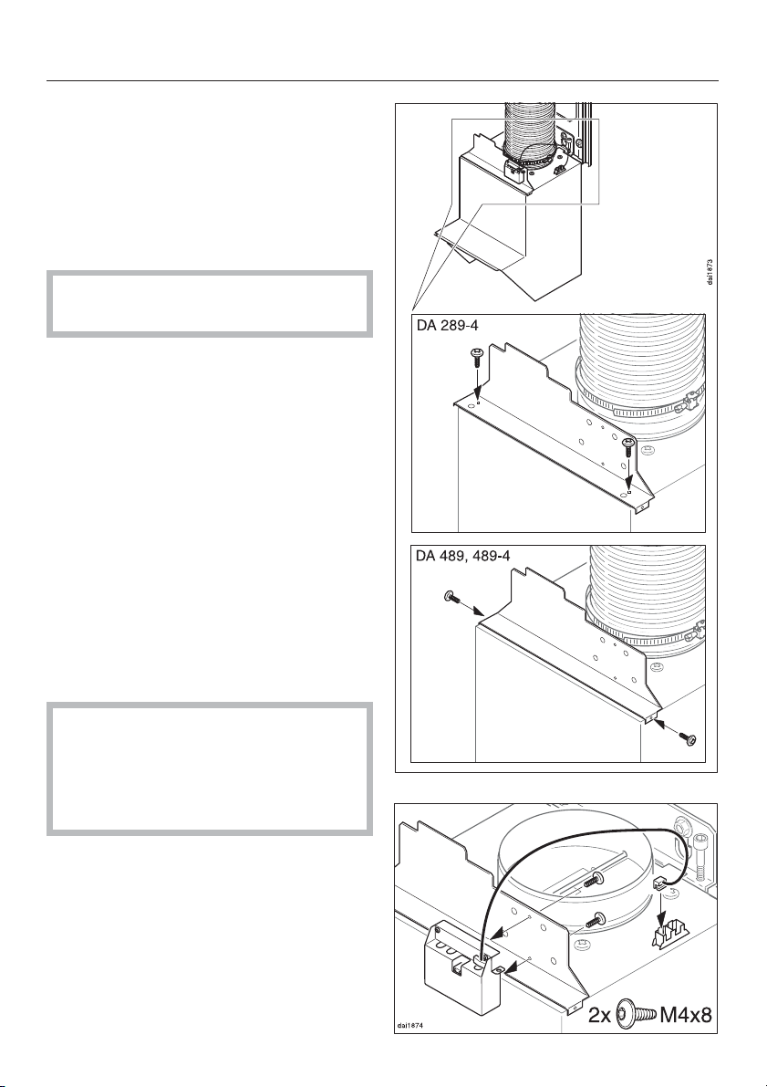
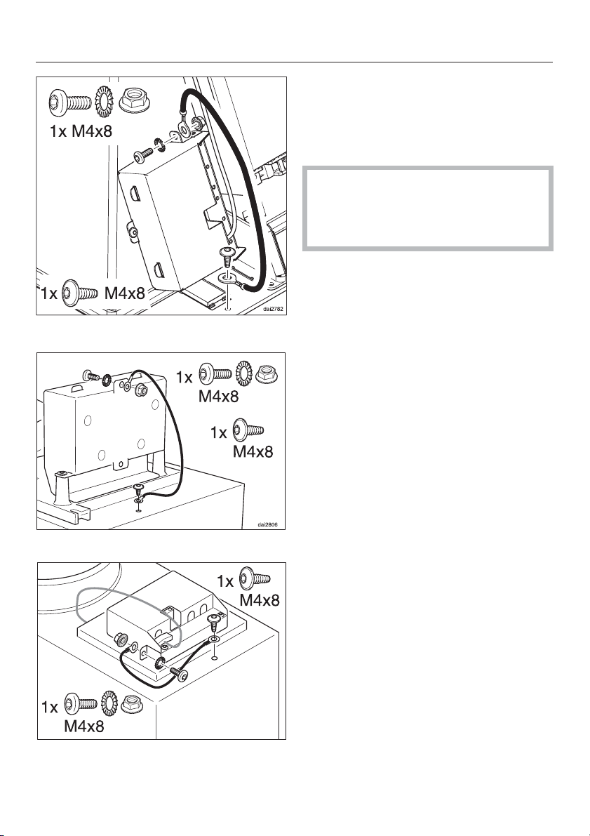
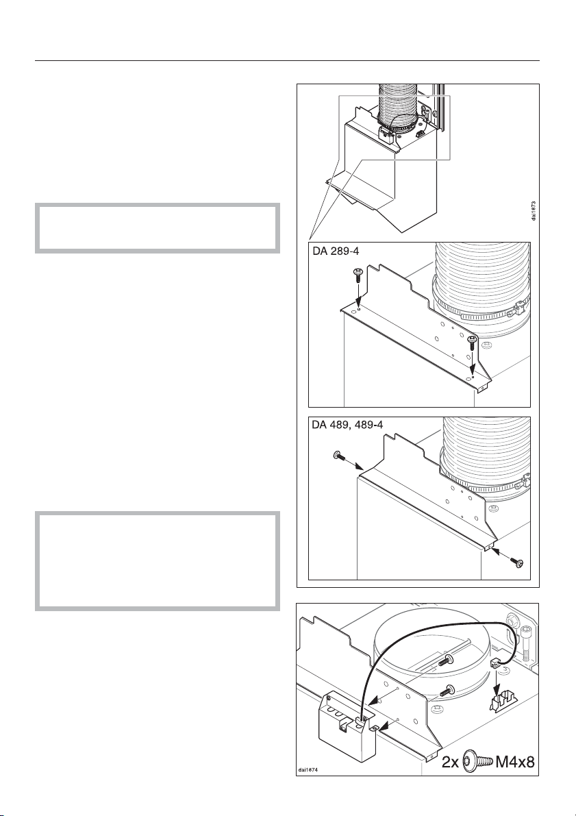
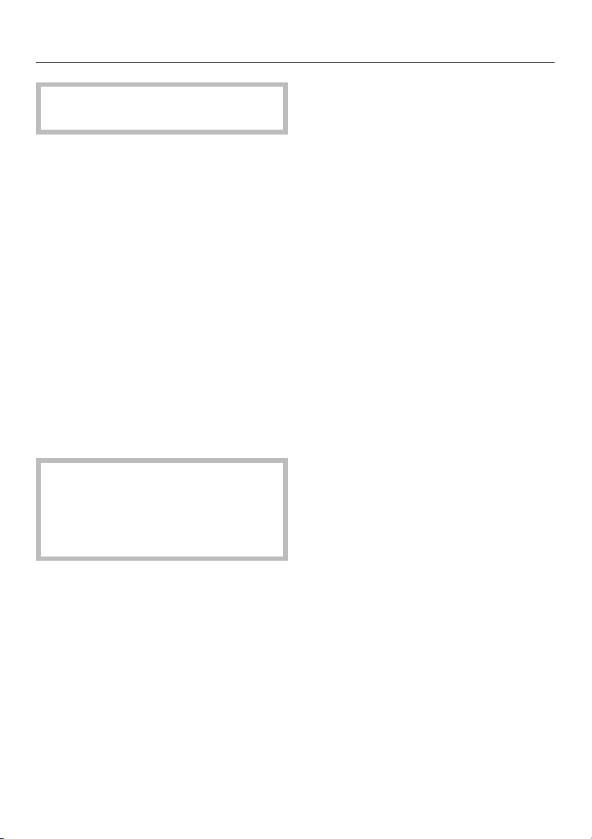
DA 289-4,
DA 489,
DA 489-4
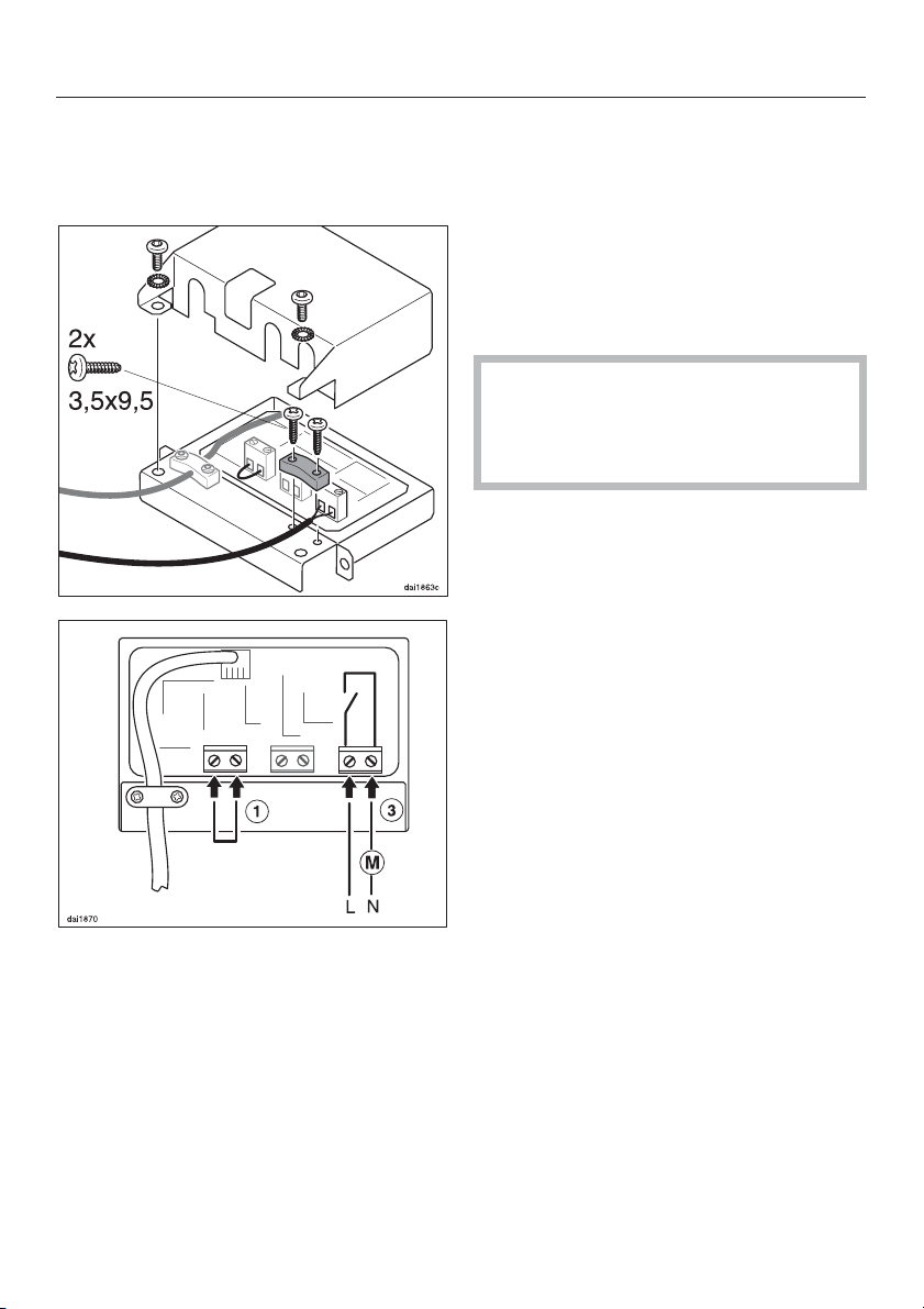
Zur Montage des Steuermoduls ist ein
Trägerblech erforderlich. Es ist als
nachkaufbares Zubehör erhältlich
(M.-Nr. 8363350).
,
Die Dunstabzugshaube vom
Stromnetz trennen.
^
Schwadenschirm, Kamin und Tele
-
skop demontieren. Beachten Sie
dazu die Montageanweisung der
Dunstabzugshaube.
^ Das Trägerblech an die Motoreinheit
montieren.
^ Die vorgesehenen Komponenten an-
schließen (siehe Kapitel "Elektrischer
Anschluss" und "Schaltplan").
^ Das Steuermodul am Trägerblech
befestigen.
^ Das Anschlusskabel in die An-
schlussbuchse auf der Motoreinheit
stecken.
Achten Sie auf eine fachgerechte
Verlegung der Anschlussleitung und
der Leitungen der angeschlossenen
Komponenten. Sie dürfen nicht ge
-
knickt oder gequetscht werden.
^
Abschließend die Dunstabzugshaube
wieder an das Stromnetz anschließen
und das Teleskop und den Kamin
wieder montieren.
de - Montage
6
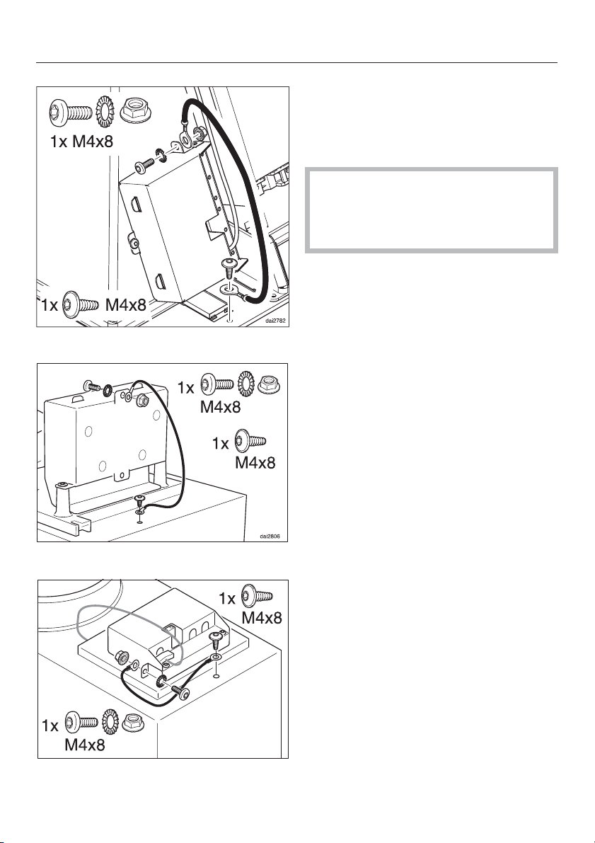
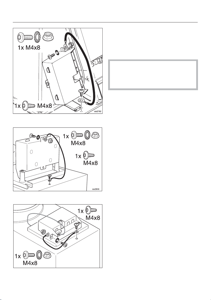
Insel-Dunstabzugshaube
,
Die Dunstabzugshaube vom
Elektronetz trennen.
^ Den Abdeckrahmen nach unten ab-
ziehen.
^ Die vorgesehenen Komponenten am
Steuermodul anschließen (siehe Ka-
pitel "Elektrischer Anschluss" und
"Schaltplan").
^
Das Steuermodul in den Schacht ein
-
schieben und mit den beiliegenden
Schrauben befestigen.
^
Das Anschlusskabel des Steuermo
-
duls in die rechte Buchse an der
Dunstabzugshaube stecken.
^
Die Kabel verlegen und den Abdeck
-
rahmen wieder aufstecken.
Achten Sie auf eine fachgerechte
Verlegung der Anschlussleitung und
der Leitungen der angeschlossenen
Komponenten. Sie dürfen nicht ge
-
knickt oder gequetscht werden.
^
Den Netzanschluss wieder herstellen.
de - Montage
7
dai2805c
4x
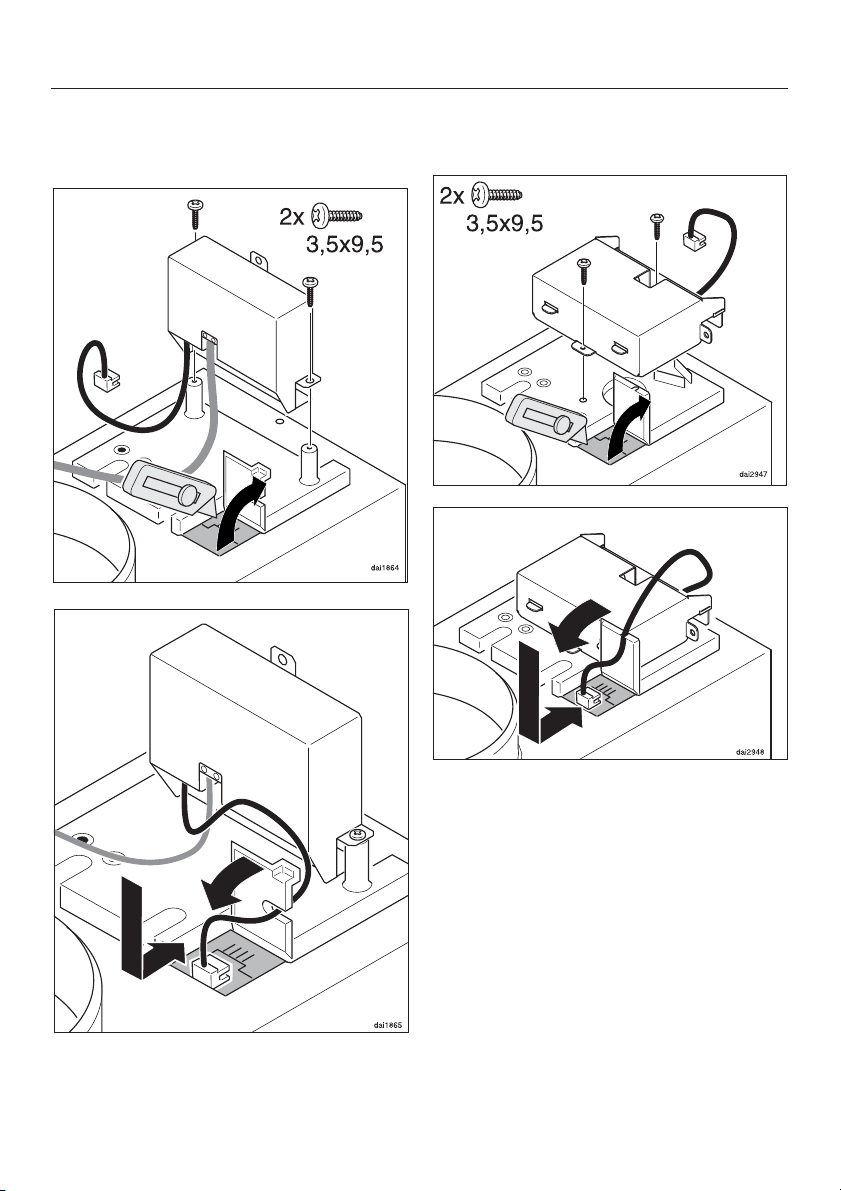
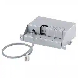
Flachschirmhaube
DA 3150/60/90
DA 3150/60/90 (2011),
DA 3460/90
de - Montage
8
,
Die Dunstabzugshaube vom
Elektronetz trennen.
^
Die vorgesehenen Komponenten am
Steuermodul anschließen (siehe Ka
-
pitel "Elektrischer Anschluss" und
"Schaltplan").
An der Oberseite der Dunstabzugshau
-
be befindet sich der Anschlusssockel
für das Steuermodul.
^
Das Steuermodul auf den Sockel
schrauben.
^ Den Deckel am Anschlusssockel mit
einem Schraubendreher öffnen.
Der Deckel kann dazu seitlich mit ei-
nem Messer eingeschnitten werden.
^ Das Anschlusskabel des Steuermo-
duls auf die Platine in der Dunstab-
zugshaube stecken.
^ Das Kabel durch die Öffnung des
Deckels verlegen und den Deckel
wieder schließen.
Achten Sie auf eine fachgerechte
Verlegung der Anschlussleitung und
der Leitungen der angeschlossenen
Komponenten. Sie dürfen nicht ge
-
knickt oder gequetscht werden.
^
Den Netzanschluss wieder herstellen.
de - Montage
9

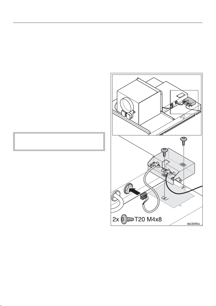
Lüfterbaustein
DA 2150, 2170, 2250, 2270, 2210
,
Die Dunstabzugshaube vom
Elektronetz trennen.
^
Die vorgesehenen Komponenten am
Steuermodul anschließen (siehe Ka
-
pitel "Elektrischer Anschluss" und
"Schaltplan").
^
Das Steuermodul mit den beiliegen
-
den Schrauben am Gehäuse der
Dunstabzugshaube befestigen.
^
Das Anschlusskabel in die Buchse
auf der Elektronikeinheit stecken.
Achten Sie auf eine fachgerechte
Verlegung der Anschlussleitung und
der Leitungen der angeschlossenen
Komponenten. Sie dürfen nicht ge-
knickt oder gequetscht werden.
^ Den Netzanschluss wieder herstellen.
de - Montage
10
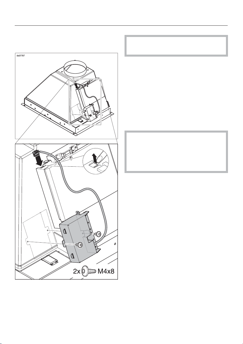
Deckenlüfter
DA 2900, DA 2905
Die beschriebene Installation des
DSM-Moduls erfolgt während der Mon
-
tage der Dunstabzugshaube. Beachten
Sie dazu die Gebrauchsanweisung und
den Montageplan der Dunstabzughau
-
be.
Zur nachträglichen Montage ist zu
-
nächst die Dunstabzugshaube auszu
-
bauen. Dies erfolgt in umgekehrter Rei
-
henfolge, wie auf dem Montageblatt der
Dunstabzugshaube beschrieben.
,
Die Dunstabzugshaube muss
vom Elektronetz getrennt sein.
^
Die vorgesehenen Komponenten am
Steuermodul anschließen (siehe Ka
-
pitel "Elektrischer Anschluss" und
"Schaltplan").
^
Die Dunstabzugshaube, wie auf dem
Montageblatt beschrieben, vorberei
-
ten.
^
Vor der Montage in der Decke das
Steuermodul mit den beiliegenden
Schrauben auf der Oberseite des
Gehäuses der Dunstabzugshaube
befestigen.
^
Das Anschlusskabel durch die vorge
-
sehene Öffnung in das Gerät führen.
de - Montage
11
^
Die Dunstabzugshaube, wie auf dem
Montageblatt beschrieben, in der De
-
cke befestigen.
Achten Sie auf eine fachgerechte
Verlegung der Anschlussleitung und
der Leitungen der angeschlossenen
Komponenten. Sie dürfen nicht ge
-
knickt oder gequetscht werden.
^
Vor dem elektrischen Anschluss der
Dunstabzugshaube die Anschlusslei
-
tung des DSM-Moduls am Anschluss
der Geräteelektronik aufstecken.
^
Die Montage der Dunstabzugshaube,
wie auf dem Montageblatt beschrie
-
ben, abschließen.
de - Montage
12
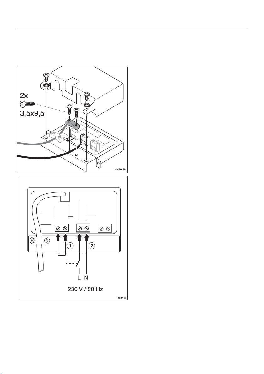
Zusatzlichttaster
(Anschluss nur durch eine Elek
-
tro-Fachkraft)
^
Zum Anschließen ist der Deckel des
Steuermoduls abzunehmen und
nachher wieder zu montieren.
^
Am mittleren Anschluss b des Steu
-
ermoduls lässt sich ein in der Ge
-
bäudeinstallation integrierter Lichttas
-
ter anschließen.
Damit kann die Beleuchtung der Dunst
-
abzugshaube ein- und ausgeschaltet
bzw. gedimmt werden (abhängig von
der Geräteausstattung).
^
Der Anschluss a muss gebrückt
werden.
Die Beleuchtung lässt sich weiterhin
auch an der Dunstabzugshaube schal-
ten.
de - Elektrischer Anschluss
13
DA 2150/70, DA 2250/70/10
DA 3150/60/90
DA 3150/60/90 (2011),
DA 3460/90
^
Flachschirmhaube und Lüfterbau
-
stein:
Die Erdungsleitung zwischen Steuer
-
modul und Gerätegehäuse ist anzu
-
schließen.
Nach der Installation aller Bauteile
hat eine Sicherheitsprüfung gemäß
der örtlichen Vorschriften zu erfol
-
gen (z.B. VDE 0701-1).
de - Elektrischer Anschluss
14
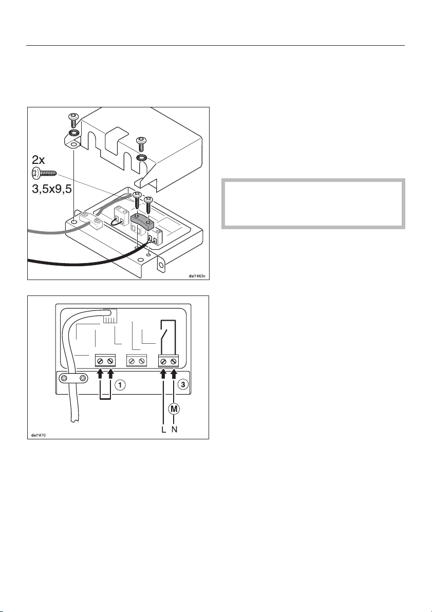
Potentialfreier Kontakt.
(Anschluss nur durch eine Elek
-
tro-Fachkraft)
^
Zum Anschließen ist der Deckel des
Steuermoduls abzunehmen und
nachher wieder zu montieren.
Der Anschluss c des Steuermoduls
bietet einen potentialfreien Kontakt. Er
kann z.B. dazu genutzt werden, andere
Geräte in Abhängigkeit vom Schaltzu
-
stand des Gebläses der Dunstabzugs
-
haube zu steuern.
Ziehen Sie in jedem Fall den Rat des
zuständigen Schornsteinfegermeis
-
ters hinzu.
^ Der Anschluss a muss gebrückt
werden.
Der Kontakt c liefert keine definierte
Spannung (potentialfrei). Damit ist er
universell einsetzbar.
Das maximale Schaltvermögen des
Kontakts beträgt 230V/2(1)A.
Der Kontakt schließt durch Einschalten
der Ein/Aus-Taste der Dunstabzugs-
haube. Die Kontrolllampe der
Ein/Aus-Taste und die zweite Kontroll
-
lampe der Gebläsestufenanzeige
leuchten.
de - Elektrischer Anschluss
15
DA 2150/70, DA 2250/70/10
DA 3150/60/90
DA 3150/60/90 (2011),
DA 3460/90
^
Flachschirmhaube und Lüfterbau
-
stein:
Die Erdungsleitung zwischen Steuer
-
modul und Gerätegehäuse ist anzu
-
schließen.
Nach der Installation aller Bauteile
hat eine Sicherheitsprüfung gemäß
der örtlichen Vorschriften zu erfol
-
gen (z.B. VDE 0701-1).
de - Elektrischer Anschluss
16

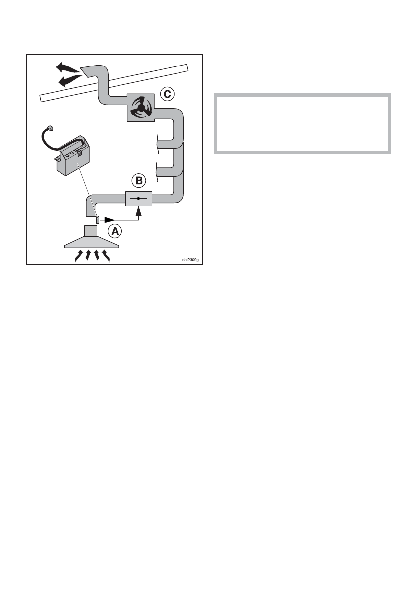
Der potentialfreie Kontakt des DSM 400
a kann zum Beispiel in einer Dunstab-
zugshaube der Baureihe ...EXT einge-
setzt werden, die an eine Zentralabsau-
gung angeschlossen ist.
Der Kontakt kann dazu genutzt werden,
eine elektrisch betriebene Absperrklap-
pe b zu betätigen, die der Zentralab
-
saugung c vorgeschaltet ist.
Die Absperrklappe muss für das Schal
-
ten mit einem potentialfreien Schlie
-
ßer-Kontakt geeignet sein.
Die Absaugleistung ist abhängig vom
verwendeten Gebläse und dem Aufbau
des Absaugsystems. Sie wird nicht
über die Bedienelemente der Dunstab
-
zugshaube geregelt.
Die Komponenten der Zentralabsau
-
gung sind nicht Bestandteil des Miele
Lieferprogramms.
Ziehen Sie in jedem Fall den Rat des
zuständigen Schornsteinfegermeis
-
ters hinzu.
de - Elektrischer Anschluss
17

The control module enables the
following:
1. Connection to a pushbutton light
switch
The control module can also be used to
switch the cooker hood lighting on via a
pushbutton light switch in the house.
2. Potential free connection
This enables another appliance to be
controlled according to the switch
setting on the cooker hood fan.
en – Installation - Operation
18

Wall mounted cooker hoods
DA 249-4,
DA 252/9-4,
DA 269/79-4,
DA 396/9-5
DA 402/6/7/9,
DA 416/9-4,
DA 422/6/8/9-4,
DA 439,
DA 446/7/9,
DA 5190 W,
DA 5294 W,
DA 5320/30/90 W,
DA 5495 W,
DA 5690 W,
DA 5960/90 W,
DA 6190 W,
DA 6290 W,
DA 6390 W,
DA 6590/20 W
,
Disconnect the cooker hood
from the mains electricity supply.
^ Dismantle the tower and the
telescopic extention piece. Follow the
separate installation instructions
supplied with the cooker hood.
^ Connect all components as
described in "Electrical connection"
and "Wiring diagram".
^ Using the screws supplied secure
the control module to the side of the
cooker hood's electronic unit.
^ Plug the connection cable into the
socket on the electronic unit.
^ Arrange the cable as shown and clip
it into the cable clips provided.
Ensure that the connection cable
and the cables of the connected
components are positioned
correctly. They should not be kinked
or squashed.
^ Finally re-connect the cooker hood to
the mains electrical supply and then
re-assemble both the telescopic
extension piece and the tower.
en - Installation
19

en - Installation
20
DA 289-4,
DA 489,
DA 489-4
A fixing bracket is required for fitting
the control module. This is available as
an optional accessory (M.-Nr.
8363350).
,
Disconnect the cooker hood
from the mains electricity supply.
^ Dismantle the canopy, tower and the
telescopic extention piece. Follow the
separate installation instructions
supplied with the cooker hood.
^ Fit the bracket to the motor unit as
shown.
^ Connect all components as
described in "Electrical connection"
and "Wiring diagram".
^ Then secure the control module to
the bracket.
^ Plug the connection cable into the
socket on the motor unit.
Ensure that the connection cable
and the cables of the connected
components are positioned
correctly. They should not be kinked
or squashed.
^ Finally re-connect the cooker hood to
the mains electrical supply and then
re-assemble the canopy, the
telescopic extension piece and the
tower.
en - Installation
21
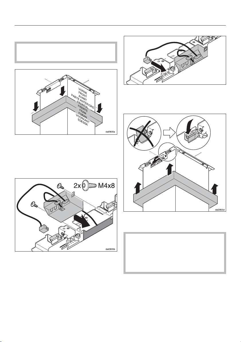
Island cooker hoods
,
Disconnect the cooker hood
from the mains electricity supply.
^ Pull the cover plate downwards.
^ Connect all components to the
control module as described in
"Electrical connection" and "Wiring
diagram".
^ Push the control module into the slot
and secure it using the screws
supplied.
^ Connect the control module cable to
the right hand socket in the cooker
hood.
^ Arrange the cable and then re-fit the
cover plate.
Ensure that the connection cable
and the cables of the connected
components are positioned
correctly. They should not be kinked
or squashed.
^ Then reconnect the cooker hood to
the mains electricity supply.
en - Installation
22
dai2805c
4x
Deflector plate cooker hoods
DA 3150/60/90
DA 3150/60/90 (2011),
DA 3460/90
en - Installation
23
,
Disconnect the cooker hood
from the mains electricity supply.
^ Connect all components to the
control module as described in
"Electrical connection" and "Wiring
diagram".
The control module connects to the top
of the cooker hood.
^ Screw the control module onto the
two pillars.
^ Open the lid to the connection box
using a screwdriver.
If necessary a knife can be used to
cut into the side of the lid.
^ Connect the control module cable to
the circuit board in the cooker hood.
^ Feed the cable through the opening
in the lid and then close the lid.
Ensure that the connection cable
and the cables of the connected
components are positioned
correctly. They should not be kinked
or squashed.
^ Then reconnect the cooker hood to
the mains electricity supply.
en - Installation
24
Integrated cooker hoods
DA 2150, 2170, 2250, 2270, 2210
,
Disconnect the cooker hood
from the mains electricity supply.
^ Connect all components to the
control module as described in
"Electrical connection" and "Wiring
diagram".
^ Using the screws supplied secure
the control module to the cooker
hood casing.
^ Plug the connection cable into the
socket on the electronic unit.
Ensure that the connection cable
and the cables of the connected
components are positioned
correctly. They should not be kinked
or squashed.
^ Then reconnect the cooker hood to
the mains electricity supply.
en - Installation
25
Ceiling mounted cooker hood
DA 2900, DA 2905
Installation of the DSM module as
described here is carried out while the
cooker hood is being installed. Follow
the instructions on how to install the
cooker hood in the separate operating
and installation instructions and the
installation diagram supplied with the
cooker hood.
If the module is being retrofitted, the
cooker hood must first be dismantled.
To dismantle the cooker hood, reverse
the procedure described in the cooker
hood installation diagram.
,
Disconnect the cooker hood
from the mains electricity supply.
^ Connect all components to the
control module as described in
"Electrical connection" and "Wiring
diagram".
^ Prepare the cooker hood as
described in the installation diagram.
^ Before fitting in the ceiling, secure
the control module to the top of the
cooker hood housing using the
screws supplied.
^ Feed the connection cable through
the opening provided into the
appliance.
en - Installation
26

^ Secure the cooker hood in the ceiling
as described in the installation
diagram.
Ensure that the connection cable
and the cables of the connected
components are positioned
correctly. They should not be kinked
or squashed.
^ Connect the DSM module connection
cable to the socket of the electronic
unit before connecting the cooker
hood to the mains electricity supply.
^ Complete the installation of the
cooker hood as described in the
installation diagram.
en - Installation
27
Additional pushbutton light
switch
(connection must be made a suitably
qualified electrician only)
^ Before making the connection the
control module lid has to be taken off.
It is refitted later.
^ Connection can be made to a
pushbutton light switch ("door bell"
type with normally open contacts) in
the home using the middle terminal
b in the control module.
This will then enable the cooker hood
lighting to be switched on and off, or
dimmed (depending on model).
^ Terminal a must be bridged.
The lighting can still be operated as
usual via the controls on the cooker
hood.
en - Electrical connection
28

DA 2150/70, DA 2250/70/10
DA 3150/60/90
DA 3150/60/90 (2011),
DA 3460/90
^ Deflector plate and integrated cooker
hoods:
Connect the earth wire between the
control module and the appliance
casing.
After the installation is completed, a
safety check must be carried out in
accordance with national and local
regulations.
en - Electrical connection
29
Potential free contact
(connection must be made a suitably
qualified electrician only)
^ Before making the connection the
control module lid has to be taken off.
It is refitted later.
Potential free contact can be made
using terminal c on the control module.
This enables another appliance to be
controlled according to the switch
setting on the cooker hood fan.
If in any doubt, the advice of a
competent builder or, for gas, a Gas
Safe registered installer must be
sought.
^ Terminal a must be bridged.
Contact c supplies no defined voltage
(it is potential free). It can be used
universally.
The maximum operating capacity of the
contact is 230V/2(1)A.
The contact closes when the On/Off
control on the cooker hood is operated.
The On/Off control indicator light and
the second indicator light for the fan
setting will come on.
en - Electrical connection
30
DA 2150/70, DA 2250/70/10
DA 3150/60/90
DA 3150/60/90 (2011),
DA 3460/90
^ Deflector plate and integrated cooker
hoods:
Connect the earth wire between the
control module and the appliance
casing.
After the installation is completed, a
safety check must be carried out in
accordance with national and local
regulations.
en - Electrical connection
31
The potential free contact on the DSM
400 a can, for example, be used in a
cooker hood with an external motor
...EXT, which is connected to a central
ducting system.
The contact can then be used to
operate an electrically driven non-return
flap b which is connected to the
central extraction unit c.
The non-return flap must be suitable for
use with a potential free contact.
The suction power depends on the
motor used and on the construction of
the ducting system. It is not controlled
via the cooker hood controls.
Components used in the central
ducting system are not supplied by
Miele.
If in any doubt, the advice of a
competent builder or, for gas, a Gas
Safe registered installer must be
sought.
en - Electrical connection
32
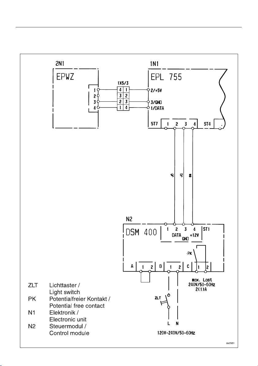
de - Wand-Dunstabzugshaube,
Lüfterbaustein
en - Wall mounted cooker hood,
Integrated cooker hood
de - Schaltplan en - Wiring diagram
33
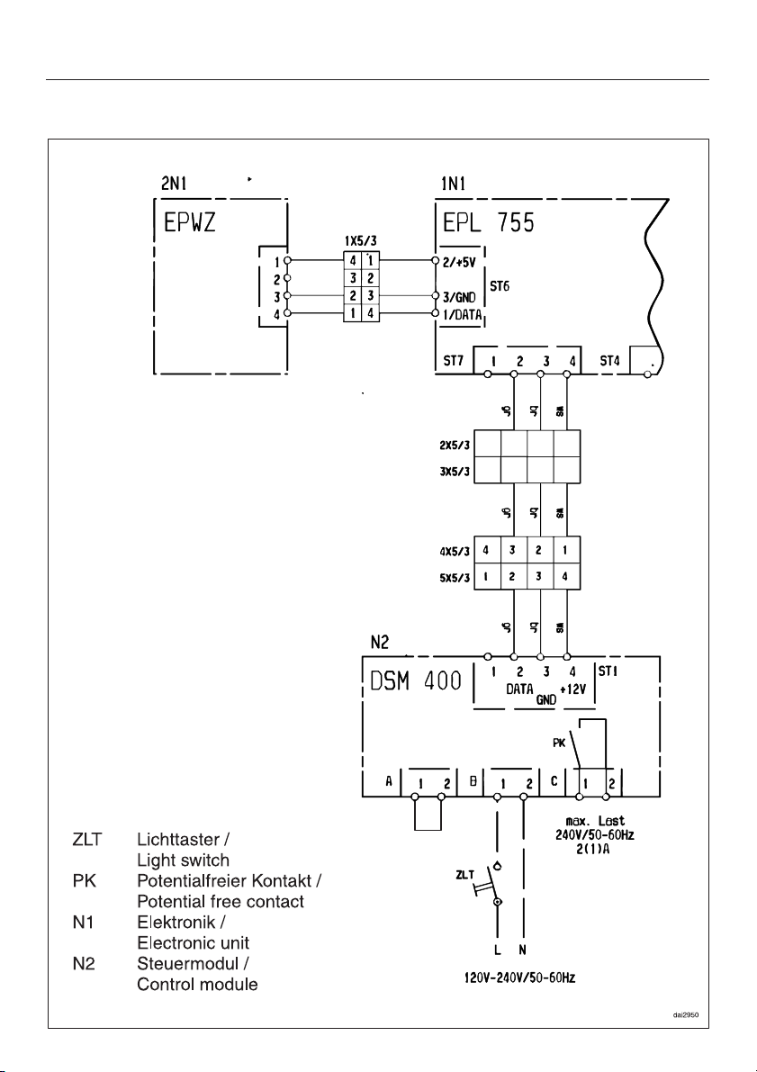
de - Insel-Dunstabzugshaube en - Island cooker hood
de - Schaltplan en - Wiring diagram
34
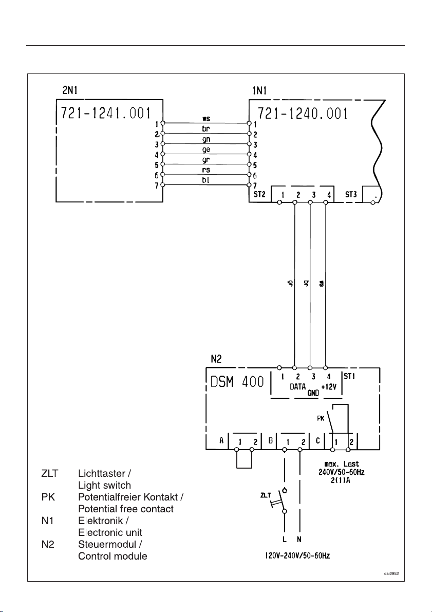
de - Flachschirmhaube en - Deflector plate cooker hoods
de - Schaltplan en - Wiring diagram
35
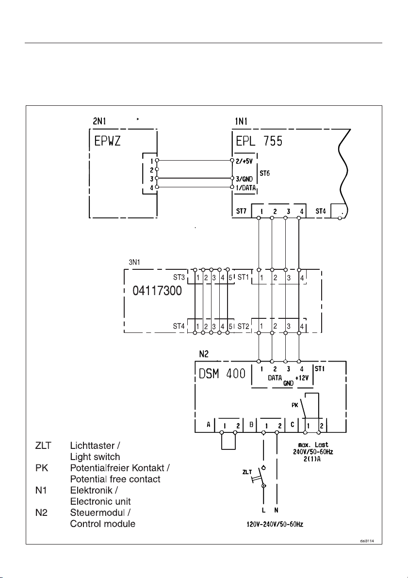
de - Deckenlüfter
DA 2900, DA 2905
en - Ceiling mounted cooker
hood
DA 2900, DA 2905
de - Schaltplan en - Wiring diagram
36

37

38

39

Änderungen vorbehalten / 3412
M.-Nr. 09 165 650 / 02