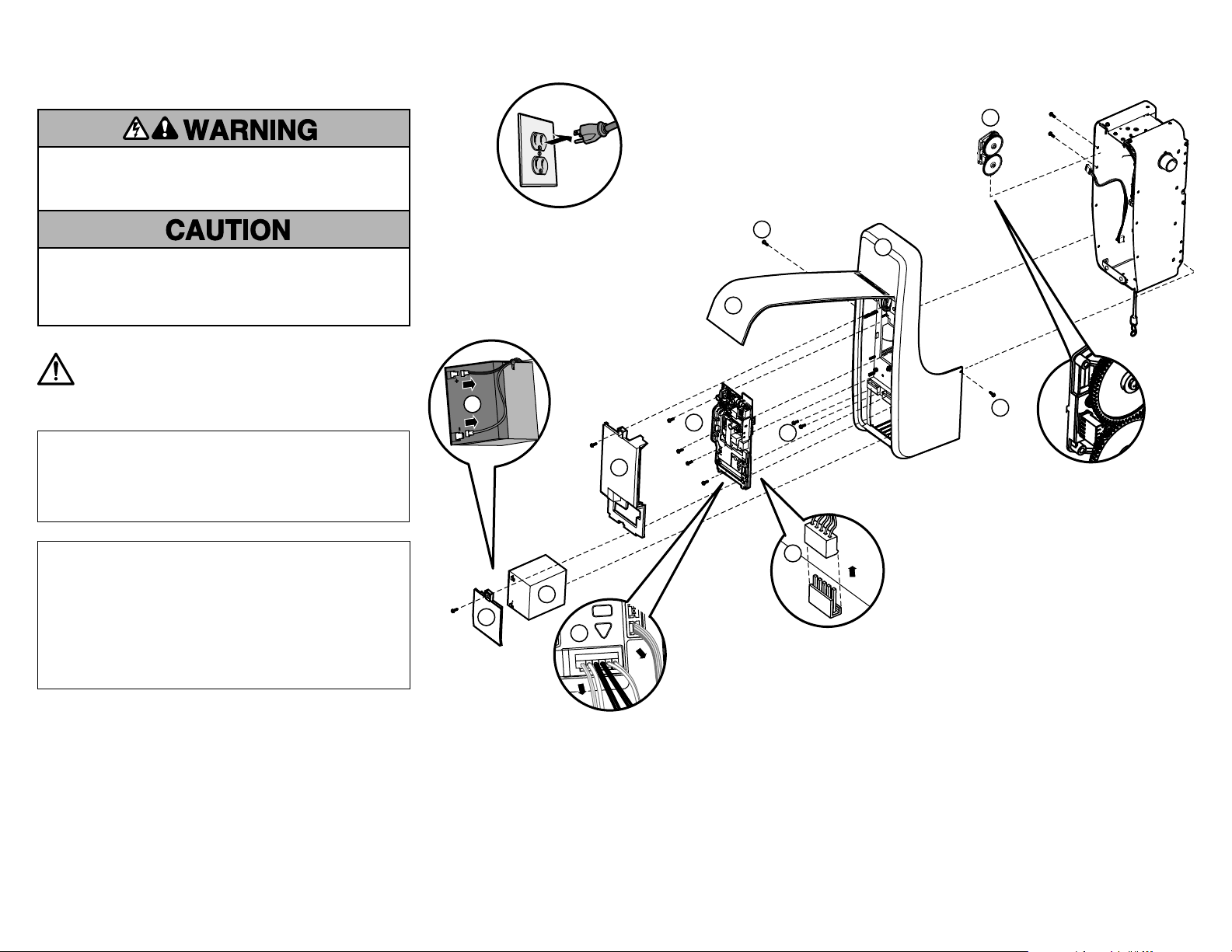
A
B
B
B
C
E
F
D
G
H
G
G
G
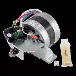
Travel Module Replacement Kit
Model 041B8861
Specifications
Volts ....................................120 Vac - 60 Hz, Only
Current ............................................1.5 AMP
Rated Load ....................................385 in/ lb./sec.
WARNING: This product can expose you to chemicals including
lead, which are known to the State of California to cause cancer or
birth defects or other reproductive harm. For more information go
to www.P65Warnings.ca.gov
To prevent possible SERIOUS INJURY or DEATH:
• Disconnect ALL electric and battery power BEFORE performing ANY
service or maintenance.
To prevent damage to the receiver/logic board, DO NOT touch printed
circuit board of replacement receiver/logic board during installation.
ALWAYS wear protective gloves and eye protection when changing the
battery or working around the battery compartment.
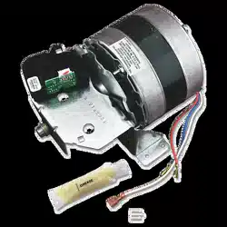
9. Remove the two screws securing
the travel module to the opener.
Disconnect 5-wire connector from the
travel module. Slide or shift the travel
module towards the front of the unit
and pull out (H).
10. Align the mounting tabs to the side
panel. Push in the travel module.
Secure travel module with screw.
Reconnect 5-wire connector.
11. Reinstall the cover. Verify that the
tabs in the cover align with the holes
in the top of the chassis. Route the
wire harnesses and wires through the
cover.
12. Install the receiver logic board and
connect the wire harnesses. Ensure
the wire harnesses are connected
properly. Route the antenna through
the channel in the cover. Install
receiver logic board cover.
13. Reconnect the wires to the quick
connect terminals (C).
14. Install the battery (if applicable) and
connect the battery connectors. Install
the battery cover.
15. Reconnect power.
Refer to your manual to reset your
travel and force settings.
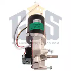
8. Remove the four screws
securing the cover to the
chassis (G).
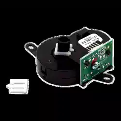
6. Unplug the wire harnesses
from the receiver logic
board (E).
7. Remove the four screws
securing the receiver logic
board, remove the logic
board (F), and set aside.
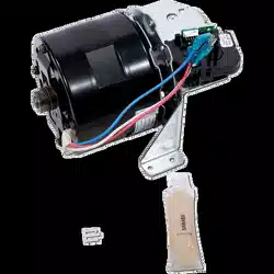
4. Label wires for reinstallation.
Disconnect the wires from the quick
connect terminals (C).
NOTE: If there is a resistor located on
the green wire traps, do not remove.
5. Remove the receiver logic board
cover (D).
1. Disconnect power.
2. Open the front panel (A).
3. Remove the battery cover.
Disconnect the battery (if
applicable). Remove the
battery and set aside. (B)
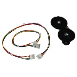
Included Items
Travel Module (1)
Screws (2)
Wire Harness (2)
- 10” for non-Wi-Fi Units
- 16” for Wi-Fi Units
Use the appropriate wire harness, referencing the existing harness for
correct length.
1
Trousse de remplacement
de module de course
Modéle 041B8861
Caractéristiques techniques
V ..............................120V c.a. - 60Hz, uniquement
Courant...............................................1,5A
Charge nominale...................................385po/lb/s
Pour éviter des BLESSURES GRAVES, VOIRE MORTELLES:
• Débrancher TOUTE alimentation électrique et la batterie AVANT
d’effectuer TOUT entretien ou TOUTE intervention.
Pour empêcher tout dommage à la carte logique/au récepteur, NE PAS
toucher le circuit imprimé du récepteur/de la carte logique de
remplacement durant l’installation.
Porter TOUJOURS des gants de protection et des lunettes de sécurité
lors du remplacement de la batterie ou d’une intervention à proximité
du compartiment de la batterie.
AVERTISSEMENT : Ce produit peut vous exposer à des produits
chimiques comme le plomb, reconnu par l’État de la Californie
comme cause de cancers, d’anomalies congénitales et d’autres
problèmes liés à la reproduction. Pour plus d’informations, visitez
www.P65Warnings.ca.gov
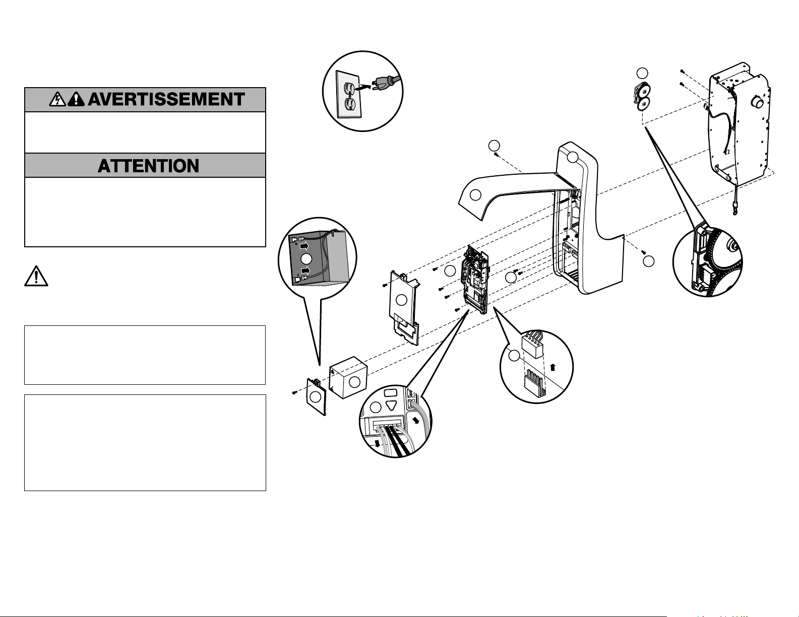
A
B
B
B
C
E
F
D
G
H
G
G
G
9. Retirer les deux vis retenant le module
de course à l’ouvre-porte. Déconnecter
le faisceau à cinq fils du module de
course. Glisser ou déplacer le module
de course vers l’avant de l’unité et
l’extraire en tirant (H).
10. Aligner les onglets de montage sur le
panneau latéral. Enfoncer le module de
course. Fixer le module de course avec
la vis. Reconnecter le connecteur à
cinqfils.
11. Remettre le couvercle en place. Vérifier
que les pattes dans le couvercle sont
alignées sur les orifices du dessus du
châssis. Acheminer les faisceaux et les
fils par le couvercle.
12. Installer la carte logique du récepteur
et connecter les faisceaux de fils.
S’assurer que les faisceaux de fils sont
connectés correctement. Réinstaller la
carte logique et connecter les faisceaux
de câblage. Installer le couvercle de la
carte logique du récepteur.
13. Raccorder les fils aux bornes à
raccordement rapide (C).
14. Installer la batterie (s’il y a lieu) et
connecter les connecteurs de la
batterie. Remettre en place le couvercle
de la batterie.
15. Reconnecter l’alimentation.
Consulter le manuel pour réinitialiser
les paramètres de course et de force.
8. Enlever les quatre vis qui
retiennent le couvercle au
châssis (G).
6. Déconnecter les faisceaux
de fils de la carte logique du
récepteur (E).
7. Enlever les quatre fils qui
retiennent la carte logique
du récepteur, enlever la
carte logique (F) et la
mettre de côté.
4. Étiqueter les fils pour la réinstallation.
Raccorder les fils aux bornes à
raccordement rapide (C).
REMARQUE: Si une résistance est
située sur les trappes de fil vert, ne
pas l’enlever.
5. Enlever le couvercle de la carte
logique du récepteur (D).
1. Déconnecter l’alimentation.
2. Ouvrir le panneau avant. (A).
3. Remettre en place le couvercle de
la batterie. Déconnecter la batterie
(s’il y a lieu). Enlever la batterie et
la mettre de côté (B).
Articles inclus
Module de course (1)
Vis (2)
Faisceau de fils (2)
- 25,4cm (10po) pour unités sans Wi-Fi
- 40,6cm (16po) pour unités avec Wi-Fi
Utiliser le faisceau de fils approprié en comparant sa longueur au
faisceau existant.
2
Juego de reemplazo del módulo
de desplazamiento
Modelo 041B8861
Especificaciones
Voltios..............................120Vca - 60Hz, solamente
Corriente...........................................1.5Amp
Carga nominal.................................385pulg./lb/sec.
Para evitar posibles LESIONES GRAVES o la MUERTE:
• Desconecte TOTALMENTE la corriente eléctrica y de la batería
ANTES de realizar CUALQUIER servicio o mantenimiento.
Para prevenir daños en el receptor/tablero lógico, NO toque el tablero
de circuito impreso de reemplazo del receptor/tablero lógico durante la
instalación.
ADVERTENCIA: Este producto puede exponerle a productos
químicos (incluido el plomo), que a consideración del
estado de California causan cáncer, defectos congénitos u
otros daños reproductivos. Para más información, visite
www.P65Warnings.ca.gov
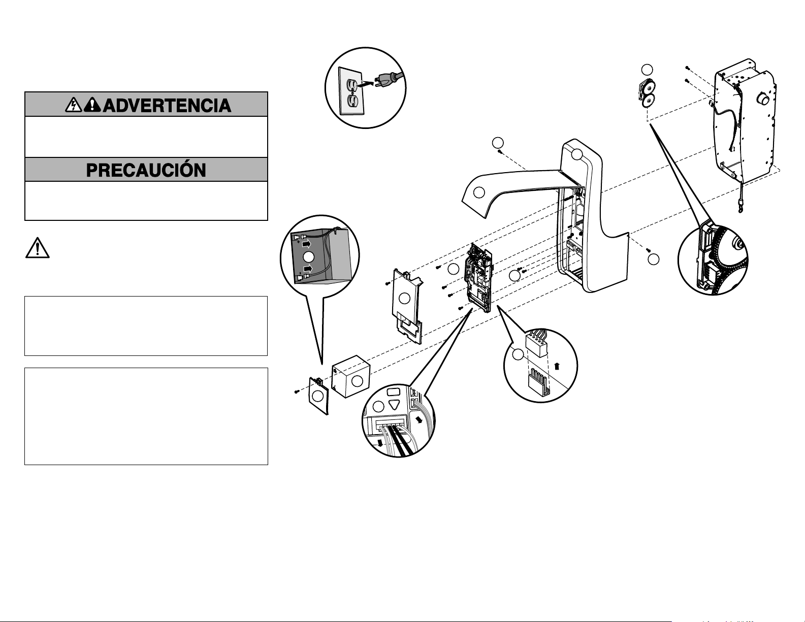
A
B
B
B
C
E
F
D
G
H
G
G
G
9. Retire los dos tornillos que sujetan el
módulo de desplazamiento al abre-
puertas. Desconecte el conector de 5
cables del módulo de desplazamiento.
Deslice o mueva el módulo de
desplazamiento hacia el frente de la
unidad y jale hacia afuera (H).
10. Alinee las lengüetas de montaje al
panel lateral. Introduzca el módulo de
desplazamiento. Asegure el módulo de
desplazamiento con tornillos. Vuelva a
colocar el conector de 5cables.
11. Volver a colocar la tapa. Verifique que las
lengüetas en la cubierta queden alineadas
con los orificios en la parte superior del
chasis. Coloque los arneses de cableado y
los cables a través de la cubierta.
12. Instale el tablero lógico del receptor
y conecte los arneses de cableado.
Asegúrese de que los arneses de
cableado estén correctamente
conectados. Coloque la antena por el
canal en la cubierta. Instale la cubierta
del tablero lógico del receptor.
13. Vuelva a conectar los cables a los
terminales de conexión rápida (C).
14. Instale la batería (si corresponde) y
conecte los conectores de esta. Instale
la cubierta de la batería.
15. Reconecte la energía.
Consulte el manual para reiniciar la
configuración de fuerza y desplazamiento.
8. Retire los cuatro tornillos
que sujetan la cubierta al
chasis (G).
6. Desenchufe los arneses
de cableado del tablero
lógico del receptor (E).
7. Retire los cuatro tornillos
que aseguran el tablero
lógico del receptor,
retírelo (F) y colóquelo a
un costado.
4. Etiquete los cables para la
reinstalación. Desconecte los
cables de los terminales de
conexión rápida (C).
NOTA: Si hay un resistor ubicado
en las trampas de alambre verde,
no lo retire.
5. Retire la cubierta del tablero
lógico del receptor (D).
1. Desconecte la energía.
2. Abra el panel delantero (A).
3. Retire la cubierta de la batería.
Desconecte la batería (si
corresponde). Retire la batería
y colóquela a un costado. (B)
Elementos que se incluyen
Módulo de desplazamiento (1)
Tornillos (2)
Arnés de cableado (2)
- 25.4cm (10 pulg.) para las unidades sin Wi-Fi
- 40.6cm (16pulg.) para las unidades con Wi-Fi
Use el arnés de cableado adecuado, tomando como referencia el arnés
existente para lograr la longitud correcta.
3

© 2017, The Chamberlain Group, Inc.
All rights reserved
Tous droits réservés
114A5123 Todos los derechos reservados