Loading ...
Loading ...
Loading ...
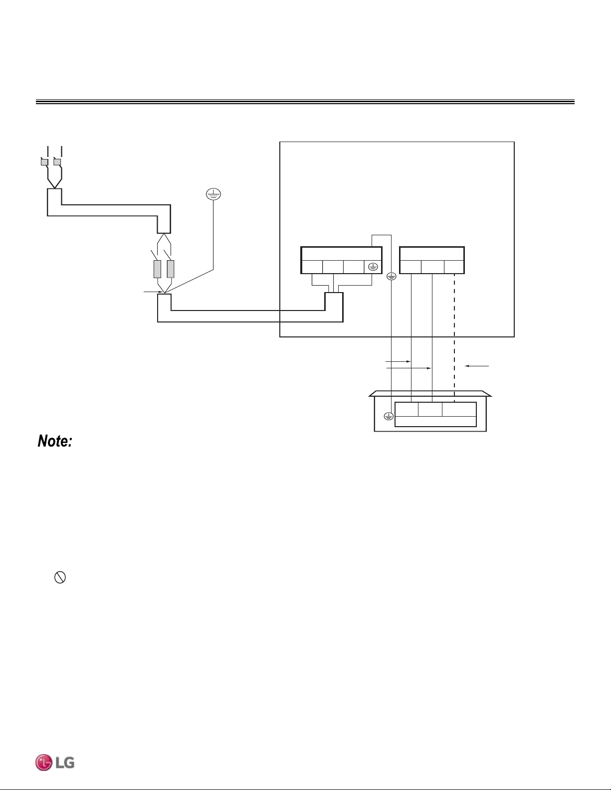
ELECTRICAL CONNECTIONS
Figure 69: Detailed Power / Communications System Schematic.
L
L
N
N
G
Power Supply
Main Switch
Circuit Breaker
Fuse
Power Wiring
(Including Ground)
Outdoor Unit
1(L1) 2(L2)
Terminal Block Outdoor
1(L1) 2(L2) 3
Terminal Block Outdoor
Communication
Cable
1(L1) 2(L2)
Terminal Block Indoor
3
Power
Wiring
Indoor Unit
• Power wiring and communications cable sizes must comply with applicable federal UL / ETL, state, and local codes.
• Separately wire the high and low voltage lines to avoid damage to unit.
• Local codes may require field-installed disconnect switches from outdoor unit to indoor unit.
• Use heat-proof electrical wire capable of withstanding temperatures up to 167°F to avoid damage to unit.
• Always use a circuit breaker or time delay fuse when connecting electrical wiring to the unit.
• Firmly connect the wire. Loose wiring may cause unit malfunction, the wires to burnout or the terminal to overheat and catch fire. There
is a risk of equipment malfunction or property damage.
• Use outdoor and waterproof connection cable rated up to 300V for the connection between the indoor and outdoor unit to avoid dam-
age to the unit.
• Comply with local codes while running wire from the indoor unit to the outdoor unit.
• Do not allow wire to touch refrigerant tubing, the compressor or any moving parts since it can lead to mechanical failure.
Due to our policy of continuous product innovation, some specications may change without notication.
©LG Electronics U.S.A., Inc., Englewood Cliffs, NJ. All rights reserved. “LG” is a registered trademark of LG Corp.
FOUR-WAY CASSETTE | 75
Electrical Connections and Mechanical Specs
Loading ...
Loading ...
Loading ...