Loading ...
Loading ...
Loading ...
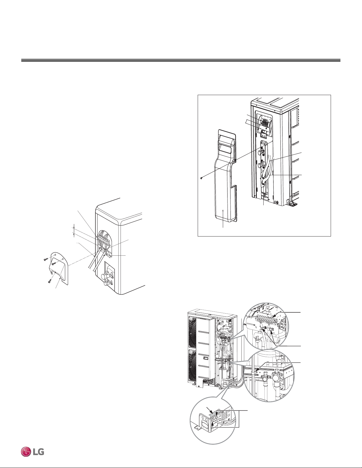
ELECTRICAL CONNECTIONS
LUU367HV, LUU427HV Outdoor Unit Connections
1. Remove the side panel.
2. Use the clamp to attach the wiring / cable.
LUU097HV, LUU127HV, LUU187HV, LUU247HV Outdoor
Unit Connections
1. Remove the cover from the unit by loosening the fastening
screws.
2. Take off the caps on the conduit panel.
3. Connect both the power supply and low voltage lines to the
corresponding terminals on the terminal block.
4. Be sure to ground the unit by following local codes.
5. Allow for enough length (add several inches) for each wiring.
6. Secure the cable with the cord clamp.
7. Secure conduit tubes with lock nuts.
8. Reattach the control cover to the original position with the fasten-
ing screws.
Figure 63: LUU097, 127HV Outdoor Unit Terminal Block Location.
Terminal block
Over 0.2”
Control cover
Conduit panel
Connecting
cable
Power supply
cord
Figure 64: LUU187, 247HV Outdoor Unit Terminal Block Location.
When connecting the power wiring /
communication cables, make sure
the rubber bushing is properly inserted
in the access holes after removing the insulation.
Insulation
Main
Terminal
Block
Clamps
Clamp
Figure 65: LUU367, 427HV Outdoor Unit Terminal Block Location.
Terminal Block
Connecting
Cable
Power
Supply
Cord
Conduit Panel
Tubing Cover
Over 0.2”
Outdoor Unit Power Wiring / Communications Cable Connections
Due to our policy of continuous product innovation, some specications may change without notication.
©LG Electronics U.S.A., Inc., Englewood Cliffs, NJ. All rights reserved. “LG” is a registered trademark of LG Corp.
FOUR-WAY CASSETTE | 73
Electrical Connections and Mechanical Specs
Loading ...
Loading ...
Loading ...