Loading ...
Loading ...
Loading ...
Due to our policy of continuous product innovation, some specications may change without notication.
©LG Electronics U.S.A., Inc., Englewood Cliffs, NJ. All rights reserved. “LG” is a registered trademark of LG Corp.
28 | FOUR-WAY CASSETTE
Four-Way Ceiling Cassette System Engineering Manual
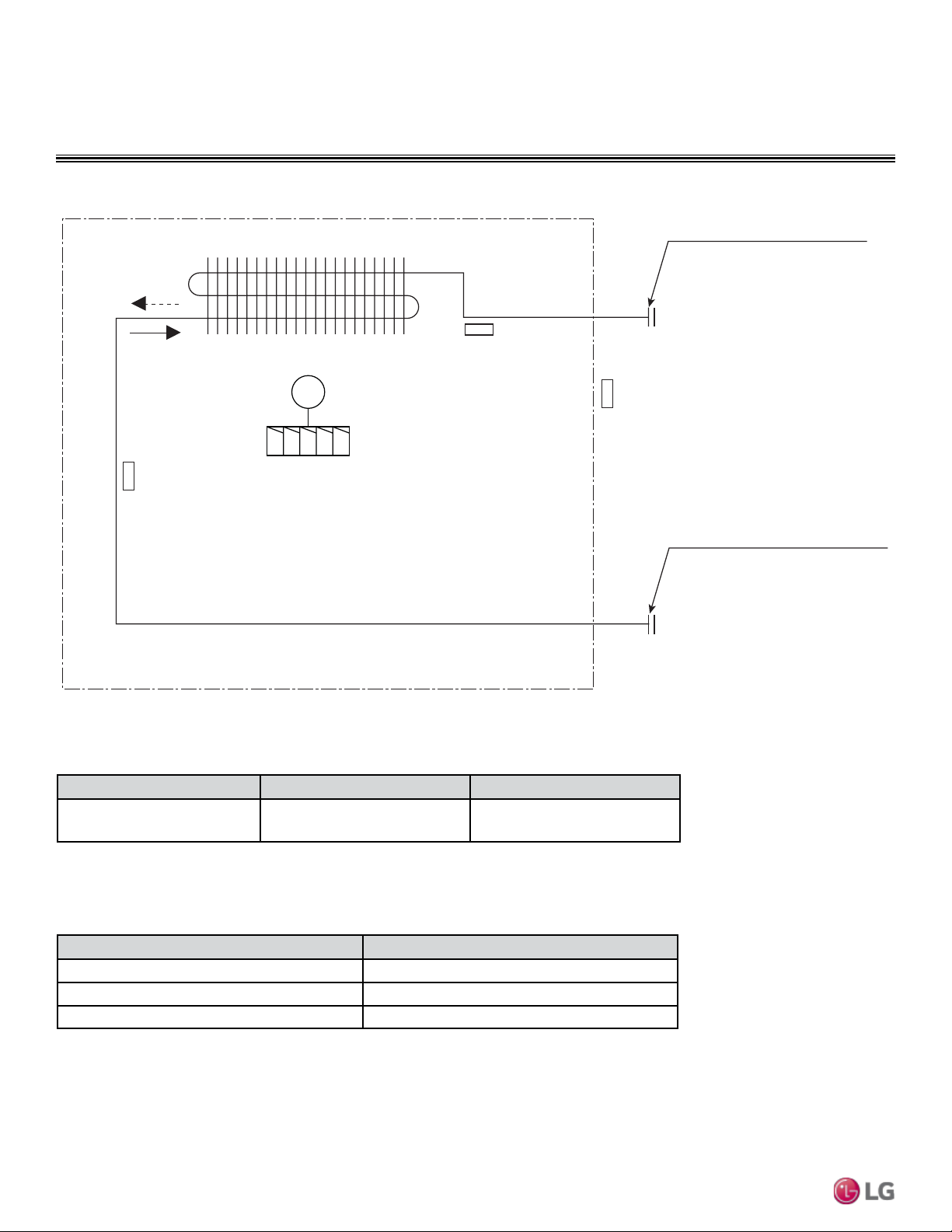
INDOOR UNIT REFRIGERANT FLOW DIAGRAM
Table 11: LCN187~427HV Four-Way Ceiling Cassette Indoor Unit Refrigerant Pipe Connection Port Diameters.
Model No. Vapor (inch) Liquid (inch)
LCN187HV, LC247HV,
LCN367HV, LC427HV
5/8 3/8
Table 12: LCN187~427HV Four-Way Ceiling Cassette Indoor Unit Thermistor Details.
Description (Based on Cooling Mode) PCB Connector
Indoor Air Temperature Thermistor CN-ROOM
Evaporator Inlet Temperature Thermistor CN-PIPE / IN
Evaporator Outlet Temperature Thermistor CN-PIPE / OUT
Heat exchanger
Gas pipe connection port
(flare connection)
Liquid pipe connection port
(flare connection)
Turbo fan
Cooling
Heating
M
Indoor Air
Temperature Thermistor
Evaporator Inlet
Temperature Thermistor
Evaporator Outlet
Temperature Thermistor
Figure 21: LCN187, 247, 367, 427HV Refrigerant Flow Diagram.
LCN187, 247, 367, 427HV
Loading ...
Loading ...
Loading ...