Loading ...
Loading ...
Loading ...
160
Integrator Mode
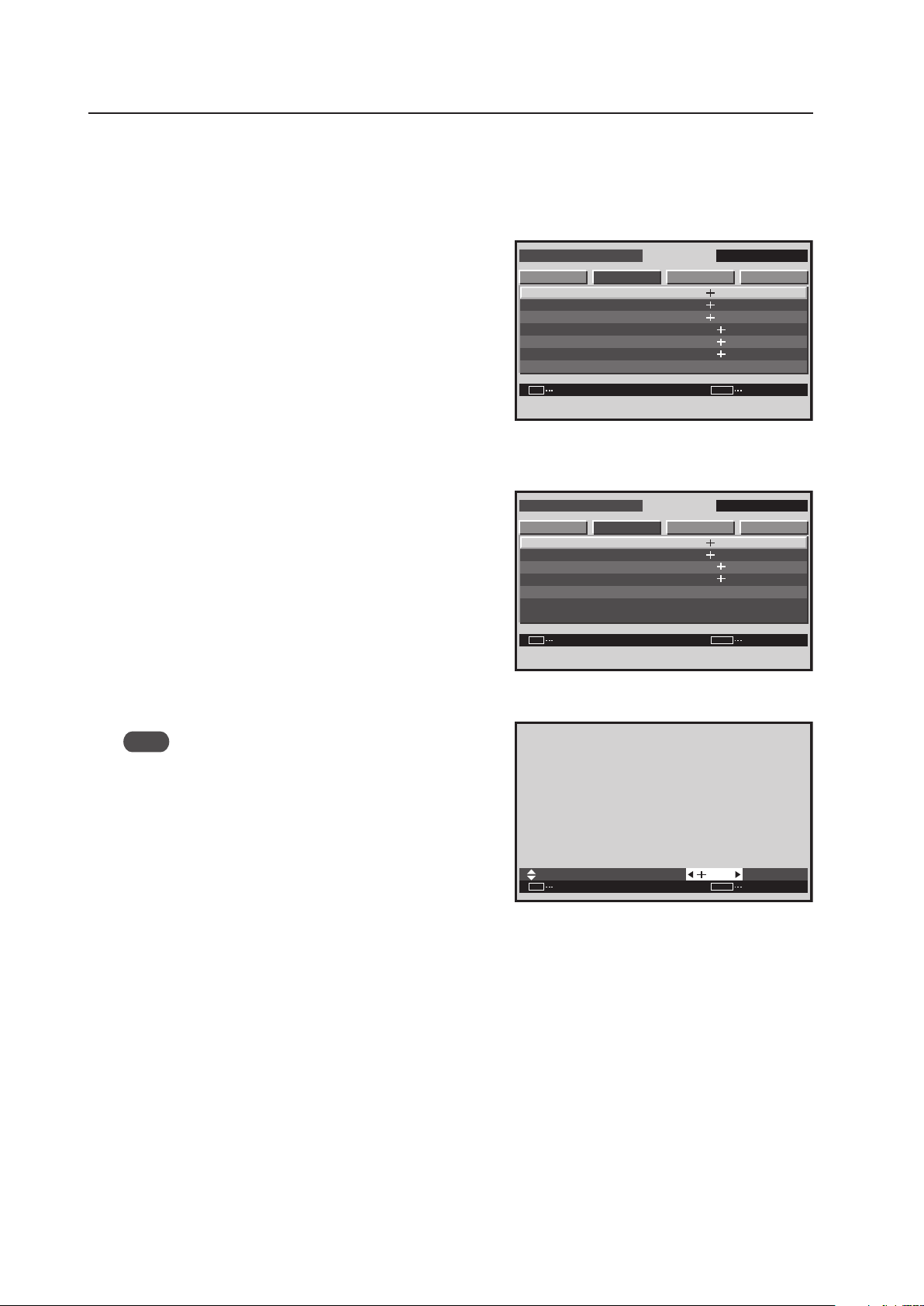
5) SCREEN (Screen Position) Adjustment
The adjustable items are H. POSITION, V. POSITION, CLOCK, PHASE, H. SIZE and V. SIZE.
1 Enter the integrator mode then switch to the input
(INPUT1 to INPUT5) to be adjusted.
2 Select ‘SCREEN’ then select the item to adjust.
In screen 2, when ‘YES’ is selected for the ‘SCREEN
RESET’, all SCREEN values return to the factory settings.
3 Perform the adjustment.
Note
‘CLOCK’ and ‘PHASE’ can be adjusted when there is PC
signal input.
Use the [5/∞] buttons on the remote control or the main-
control panel to select a different item.
Use the [2/3] buttons on the remote control or the main-
control panel to change settings.
The values adjusted here become the menu mode’s initial
values.
Press the [SET] button to return to screen 2.
<Adjustable Range>
H. POSITION, V. POSITION when there is PC signal input: 0 to 255 (initial value: 128)
H. POSITION, V. POSITION when there is video signal input: 0 to 127 (initial value: 64) (When a PDA-5003/PDA-
5004 is used.)
H. SIZE, V. SIZE: 0 to 63 (initial value: 0)
CLOCK: 0 to 255 (initial value: 128)
PHASE: 0 to 31 (initial value: 16)
<Adjustment Order>
Performing adjustment in the following order is effective.
V. POSITION H. POSITION CLOCK H. POSITION CLOCK PHASE
I N T E G R ATO R I N P U T 1
ENTER
S C R E E N S E T U P OP T I O N
H . P O S I T O I N
V . P O S I TO I N
C L O C K
P H A S E
S C R E E N R E S E T
H . S I Z E
V . S I Z E
PICTURE
: 1 2 8
: 1 6
: 3 2
: 3 2
: 1 2 8
SET
EXIT
MENU
: 1 2 8
Screen 2
For PC signal input
:
SET
SET EXIT
MENU
1 2 8
H . P O S I T I O N
Screen 3
I N T E G R ATO R I N P U T 1
ENTER
S C R E E N S E T U P OP T I O N
H . P O S I T O I N
V . P O S I TO I N
S C R E E N R E S E T
H . S I Z E
V . S I Z E
PICTURE
: 3 2
: 3 2
: 1 2 8
SET
EXIT
MENU
: 1 2 8
For video signal input
(Applicable only when a PDA-5003/PDA-5004 is
installed.)
Loading ...
Loading ...
Loading ...