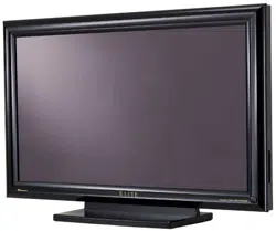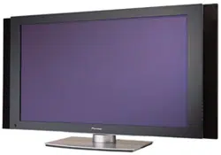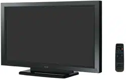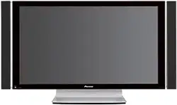
PLASMA DISPLAY MONITOR: PDP-425CMX/PDP-42MXE10/PDP-42MXE10-S
VIDEO CARD: PDA-5003/PDA-5004
TABLE TOP STAND: PDK-TS01
TILT MOUNT UNIT: PDK-5011
WALL MOUNT UNIT: PDK-WM01
CEILING MOUNT UNIT: PDK-5012
MOBILE CART: PDK-5014
SPEAKER SYSTEM: PDP-S44-LR/PDP-S52-LR
ABOUT MOUNTING/INSTALLATION
÷ This product is sold under the assumption that
installation will be performed by experienced,
qualified experts. Refer all mounting and
installation work to qualified personnel, or consult
the nearest PIONEER dealer for assistance.
÷ We accept no responsibility for accident or loss
resulting from failure to select an appropriate
installation site, or for those occurring during
assembly, installation, mounting, or operation of
this product, or resulting from modifications made
to this product, or from natural disasters.
PRECAUTIONS:
• We accept no responsibility for losses resulting from
the use of parts other than those supplied by us.
• We guarantee the performance of our products only
when they are assembled and adjusted as described in
this manual.
• The specifications and external designs shown in this
manual are subject to change without notice.
CAUTION
Exclamation marks placed within triangles are
intended to alert users to the presence of important
safety information. Be sure to read instructions
indicated by this symbol.
This manual provides precautions and information for installation, preparation, and handling of the Plasma Display and
its dedicated mounting hardware.
Before installation and preparatory work, choose a safe and appropriate site after thorough consideration of construction,
materials used, strength, and surroundings. If adequate safeguards are not in place, immediately halt the installation
process and discontinue marketing activities.
TECHNICAL MANUAL (Ver. 1.2)
FOR PIONEER PLASMA DISPLAY MONITOR WHEN USED WITH
VIDEO CARDS (EXPANSION SOLUTIONS CARDS)

2
Table of Contents
INTRODUCTION ..................................................................... 4
FEATURES .............................................................................. 5
SPECIFICATIONS
2.1 Specifications ............................................................... 6
2.2 External Dimensions .................................................... 8
2.3 Controls and Connectors ........................................... 10
2.4 Pin layout .................................................................... 13
2.5 Remote Control Unit .................................................. 14
2.6 Remote Control Unit Holder ..................................... 15
INSTALLATION SITE REQUIREMENTS
3.1 Installation Site Requirements .................................. 16
3.2 Installation Conditions ............................................... 18
3.2.1 Heat dissipation ................................................ 18
3.2.2 Calculating heat quantity ................................... 19
3.2.3 Product mounting holes .................................... 19
3.2.4 Mounting surface warping ................................ 21
3.3 Installation Procedures .............................................. 22
3.3.1 Transportation precautions ............................... 22
3.3.2 Unpacking ......................................................... 22
3.3.3 Mounting on the attachment stands ................. 23
3.3.4 Re-packing ........................................................ 24
3.3.5 Wiring ................................................................ 24
3.4 Special Installation ..................................................... 26
3.4.1 Mounting to fittings .......................................... 26
3.4.2 Hanging on the wall .......................................... 28
3.4.3 Embedding in the wall ...................................... 30
3.4.4 When the display is put in a box ....................... 33
3.4.5 Ceiling suspension (with wires) ........................ 34
3.4.6 Hanging on the wall lengthwise ........................ 36
3.4.7 Place product upright and flush into wall
(embedding in the wall) ..................................... 38
3.4.8 Installed facing upward ..................................... 42
3.4.9 Horizontal connections ...................................... 44
3.4.10 Multiple ............................................................. 45
HOW TO USE THE STANDARD MOUNTING COMPONENTS
4.1 Standard Mounting Components Features and
Characteristics ............................................................ 46
4.2 Handling the Standard Mounting Components ...... 47
4.2.1 Handling precautions ........................................ 47
4.2.2 Precautions for installation contractors ............. 47
4.3 Installation of the Attachment Stand ....................... 48
4.4 Video Card: PDA-5003/PDA-5004 .............................. 50
4.4.1 Specifications .................................................... 50
4.4.2 External Dimensions ......................................... 52
4.4.3 Installing procedures ......................................... 54
4.5 Table Top Stand: PDK-TS01 ...................................... 58
4.5.1 Specifications .................................................... 58
4.5.2 Installation coordinates for screws used to
stabilize the stand to the floor ........................... 59
4.5.3 External Dimensions ......................................... 59
4.5.4 Stand assembling .............................................. 60
4.5.5 Attaching the Stand to the Plasma Display ....... 60
4.6 Tilt Mount Unit: PDK-5011 ......................................... 64
4.6.1 Specifications .................................................... 64
4.6.2 External Dimensions ......................................... 65
4.6.3 Assembling the mounting hardware and
mounting the Plasma Display ........................... 66
4.6.4 Angle setup ....................................................... 68
4.6.5 Measure to prevent shakiness when the unit is
installed at a slight tilt ....................................... 69
4.7 Wall Mount Unit: PDK-WM01 .................................... 70
4.7.1 Specifications .................................................... 70
4.7.2 External Dimensions ......................................... 71
4.7.3 Assembling the mounting hardware and
mounting the display ......................................... 72
4.7.4 When removing the Plasma Display ................. 74
4.8 Ceiling Mount Unit: PDK-5012 .................................. 76
4.8.1 Specifications .................................................... 76
4.8.2 External Dimensions ......................................... 77
4.8.3 Installing the mounting hardware ..................... 78
4.8.4 Attach the Plasma Display ................................ 79
4.8.5 Angle setup ....................................................... 80
4.9 Mobile Cart: PDK-5014 ............................................... 82
4.9.1 Specifications .................................................... 82
4.9.2 External Dimensions ......................................... 83
4.9.3 Disassembling the display stand ....................... 84
4.9.4 How to install .................................................... 84
4.10 Speaker System: PDP-S44-LR/PDP-S52-LR ............ 88
4.10.1 Specifications .................................................... 88
4.10.2 External Dimensions (when mounted to the
Plasma Display) ................................................. 89
4.10.3 Installation on the Plasma Display .................... 90
BEFORE BEGINNING ADJUSTMENT/SETTING
5.1 Before Beginning Adjustment .................................. 92
5.1.1 Operation Mode ................................................ 92
5.1.2 Combined Use of the Remote Control,
Main-control Panel, and RS-232C commands ... 93
5.1.3 List of Input Correspondence Signals ............... 94
5.1.4 List of Adjustable and Settable Items ............. 103
5.1.5 Last Memory ................................................... 111
5.1.6 Aging ............................................................... 111
5.2 Normal Operation Mode ......................................... 112
5.2.1 About normal operation mode ........................ 112
5.3 Menu Mode .............................................................. 114
5.3.1 About menu mode .......................................... 114
5.3.2 Concerning the display of the OSD
of each item .................................................... 114
5.3.3 Example of a Menu Mode Operation .............. 115
5.3.4 Adjustment and setting in the Menu Mode .... 116
1) Power Management Setting .................... 116
2) Signal Format Setting ............................... 117
3) Menu Language Display Setting ............... 118
4) Energy Saving Setting .............................. 119
5) Orbiter Setting .......................................... 121
6) Soft Focus Setting .................................... 122
7) Auto Set Up Mode Setting ....................... 123
8) Screen Position, Clock Frequency and
Clock Phase Adjustment .......................... 124
9) Auto Function Mode Setting .................... 126
10) Timer Setting ............................................ 127
11) Program Timer Setting ............................. 127
12) PIP DETECT Setting ................................. 128
13) SPLIT FREEZE Setting .............................. 129
5.3.5 Concerning the display of the OSD of each item
(Applicable only when a PDA-5003/PDA-5004 is
installed.) ......................................................... 130
5.3.6 Example of a Menu Mode Operation .............. 130
5.3.7 Adjustment and setting in the Menu Mode .... 131
1) Color Temperature Setting ....................... 131
2) Power Management and Auto Power OFF
Setting ...................................................... 132
3) DNR (digital noise reduction) Setting ........ 133
4) MPEG NR Setting ..................................... 134
5) CTI Setting ................................................ 135
6) PURECINEMA Setting .............................. 136
7) Color System Setting ................................ 138
8) Signal Format Setting ............................... 139
9) DVI Setting ............................................... 140
10) Color Decoding Setting ............................. 141
11) Menu Language Display Setting ............... 142
12) Energy Saving Setting .............................. 143
13) Orbiter Setting .......................................... 145
14) Soft Focus Setting .................................... 146

3
Table of Contents
CAUTION
• To prevent injury and material damage, thoroughly read
this manual and all labels found on the equipment before
attempting to mount, install, move, or adjust the product.
• Do not install the unit outside or in the open air. Doing
so will lead to water seepage into the system, resulting
in fire or electric shock.
• Be especially careful when working around parts of the
system that have sharp edges.
• When performing installation work from a height, take
suitable precautions to guard against falling. Set up a
barrier around the work site to prevent accidentally
dropped objects that can injure people standing or
walking below. Tampering with the unit may result in
fire or electrical shock.
• Keep all foreign objects out of the unit. Tampering with
the unit may result in fire or electrical shock.
• Observe the following operating environmental
limitations:
Temperature: 0 °C to 40 °C
Humidity: 20 % to 80 %
• Install the unit only in properly ventilated areas.
15) Auto Set Up Mode Setting ....................... 147
16) Screen Position, Clock Frequency and
Clock Phase Adjustment .......................... 148
17) Auto Function Mode Setting .................... 150
18) Timer Setting ............................................ 151
19) Program Timer Setting ............................. 151
20) Subscreen Mode Setting .......................... 152
21) PIP DETECT Setting ................................. 153
5.4 Integrator Mode ....................................................... 154
5.4.1 About the Integrator Mode ............................. 154
5.4.2 Example of Integrator Mode Operation .......... 155
5.4.3 Adjustment and Setting in the Integrator Mode ... 156
1) PICTURE Adjustment ............................... 156
2) WHITE BALANCE Adjustment ................. 157
3) COLOR DETAIL setting ............................ 158
4) GAMMA Setting ....................................... 159
5) SCREEN (Screen Position) Adjustment .... 160
6) Brightness Enhancement (BRT. ENHANCE)
Setting at the Center of the Screen .......... 161
7) SUB VOLUME Setting .............................. 162
8) Program Timer Setting ............................. 163
9) SCREEN MASK Setting ............................ 164
10) SIDE MASK Setting .................................. 165
11) VIDEO WALL Setting ............................... 166
12) BAUD RATE Setting ................................. 170
13) Assigning an ID ......................................... 171
14) Cooling Fan Control Setting ...................... 172
15) OSD Display Setting ................................. 173
16) FRONT INDICATOR Setting ..................... 175
17) COLOR MODE Setting ............................. 176
18) PRO USE Setting ...................................... 177
19) FRC Setting .............................................. 179
20) POWER ON MODE Setting ...................... 181
21) SEAMLESS SW Setting ............................ 182
22) MIRROR MODE Setting ........................... 183
23) MULTISCREEN Setting ............................ 185
24) FUNCTIONAL LOCK ................................. 187
5.4.4 PICTURE, White Balance and SCREEN Position
Adjustment Values Memory Area Tables ....... 188
5.5 RS-232C Adjustment ................................................ 193
5.5.1 About the RS-232C Adjustment ...................... 193
5.5.2 Interface .......................................................... 194
5.5.3 Combination Connection ................................. 195
5.5.4 ID Assignment ................................................ 196
5.5.5 List of RS-232C Commands ............................ 198
5.5.6 QUEST Commands ......................................... 204
5.6 Screen Burning ........................................................ 211
5.7 Precautions on Connecting Camera Images ......... 212
5.8 Concerning frame delay (lip sync) .......................... 212
PRECAUTIONS
6.1 Precautions ............................................................... 213
MAINTENANCE .................................................................. 214
* The difference of PDP-42MXE10 and PDP-
42MXE10-S is front-bezel color.
PDP-42MXE10-S is the model of which color of
front-bezel is silver. Please refer the specification
of PDP-42MXE10 about the spec. of this unit.
* The difference of PDP-S44-LR and PDP-S52-LR
is baffle color.
PDP-S52-LR is the model of which color of baffle
is silver. Please refer the specification of PDP-
S44-LR about the spec. of this unit.
4
Introduction
Introduction
The contents of “5.1 Before Beginning Adjustments (pg. 92)” and subsequent sections are premised on the PDP-
425CMX/PDP-42MXE10 being equipped with the PDA-5003 or PDA-5004. Items that apply only when the PDA-5003 or
PDA-5004 is installed are marked with a star ‘★’.
With the PDA-5003 or the PDA-5004 installed, the PDP-425CMX/PDP-42MXE10 supports the following functions:
Input/output terminals
7 PDA-5003
INPUT 1 Input • Component video signal
• RGB signals from AV devices other than PCs
INPUT 2 Input • Digital video signal (HDCP supported)
INPUT 3 Input • Y/C separate video signal
INPUT 4 Input • Composite video signal
Output • Composite video signal
INPUT 3/ Input • Audio L/R signal
INPUT 4
INPUT 5 Input • Composite video signal
• RGB signals from AV devices or PCs
• Audio L/R signal
7 PDA-5004
INPUT 1 Input • Component video signal
• RGB signals from AV devices other than PCs
INPUT 2 Input • Digital video signal (HDCP supported)
INPUT 3 Input • Y/C separate video signal
• Audio L/R signal
INPUT 4 Input • Composite video signal
• Audio L/R signal
Output • Composite video signal
INPUT 5 Input • Composite video signal
• RGB signals from AV devices or PCs
• Audio L/R signal
Precautions

5
Features
Features and Functions of this device
¶ Introduces newly developed 42" Wide Plasma
Panel
The new wide high-precision 42" plasma panel (1024x768
/ 16:9) pushes the envelope of previous high-luminance
panels, producing brighter, clearer images with higher
contrast.
¶ Provides an ES Slot interface for enhanced
potential
The display has a built-in ES Slot Interface for installing third-
party cards. Cards allow external devices to communicate
with the panel, enhancing and expanding its potential.
¶ Supports wide range of computer signals
(analog/digital)
The panel supports non-compressed signals ranging from
640x400 and 640x480 (VGA) to 1024x768 (XGA), and
compressed display of 1280x1024 (SXGA), 1400x1050
(SXGA+) and 1600x1200 (UXGA) signals. Further, aspect
ratio and screen size settings support [DOT BY DOT], [4:3],
and [FULL] (*1).
* Supported signals are different on INPUT1 and INPUT2.
*1 Aspect ratio and screen size appearance differs
depending upon input signal.
¶ Free Installation Configuration
– Broader installation possibilities with thinner,
lighter, high-endurance design –
While producing a large 42" screen image, the display is
only 98 mm thick and weighs in at only 30.5 kg. The
efficient heat-radiating design greatly improves
environmental operating conditions. The thinner, lighter
design coupled to high-endurance construction greatly
broadens the range of possible installation locations.
¶ High reliability for commercial applications
This display is highly dependable in commercial
applications because of its ability to supress peak
luminance during viewing and adjust cooling fan speeds
when the operating environment changes.
Such features provide safety and high-endurance under
conditions of commercial use.
¶ Improved usability
User convenience is improved by making the display more
compatible with your computer. Some of these
improvements include the one-touch screen adjustment
[AUTO SET UP] function for computer connections and
the POINT ZOOM function to enlarge selected portions
of the screen image to show detailed program data.
¶ Power-Saving Design
The display has a variety of power-saving functions including
an automatic brightness function with ambient light sensing.

6
Power requirements
PDP-425CMX .......................... AC 100 V to 120 V, 50/60 Hz
PDP-42MXE10 ........................... AC 100 V to 240 V, 50/60 Hz
(The power unit range is from AC100 V to 240 V (50/60 Hz))
In-rush
PDP-425CMX ................................................. less than 30 A
PDP-42MXE10 ................................................. less than 50 A
Power factor .................................................... more than 0.95
Consumption
PDP-425CMX ......................285 W
(NOTE 2)
(1.2 W in standby)
PDP-42MXE10 .................... 360 W
(NOTE 2)
(1.5 W in standby)
External dimensions (not including the handles and supplied stand)
........................... 1022 mm (W) × 610 mm (H) × 98 mm (D)
40-1/4 in. (W) × 24-1/32 in. (H) × 3-27/32 in. (D)
Weight (without attachment stand) ......... 30.5 kg (67.3 lbs.)
Dimensions of packaging
......................... 1177 mm (W) × 767 mm (H) × 354 mm (D)
46-11/32 in. (W) × 30-7/32 in. (H) × 13-31/32 in. (D)
Weight when packaged ................................. 38 kg (83.8 lbs.)
Operating Temperature .... 0 °C to 40 °C (32 °F to 104 °F)
(NOTE 3)
Operating Humidity .......................................... 20 % to 80 %
Operating atmospheric pressure .......... 800 hPa to 1114 hPa
Storage limitations (when installed)
Temperature .................. –20 °C to +60 °C (–4 °F to 140 °F)
Humidity ......................................................... 20 % to 90 %
Atmospheric pressure ......................... 700 hPa to 1114 hPa
Storage limitations (when in original package)
Temperature ................ –30 °C to +60 °C (–22 °F to 140 °F)
Humidity ......................................................... 20 % to 90 %
Atmospheric pressure ......................... 700 hPa to 1114 hPa
Stacking ............................................ Fewer than three tiers
Standard accessories
Power cord .............................................................................. 1
Ferrite core (for power cord) ................................................... 2
Ferrite core (for audio cables) ................................................. 3
Cable tie .................................................................................. 2
Remote control unit ................................................................ 1
AA battery ............................................................................... 2
Wiping cloth (for screen) ......................................................... 1
Speed clamp ........................................................................... 5
Operating instructions ............................................................. 1
Warranty (PDP-425CMX only) ................................................. 1
Remote control unit holder ..................................................... 1
Display stand ........................................................................... 2
Washer .................................................................................... 2
Hexagon socket head screw (M8 x 40) ..................................
2
Specifications and external designs are subject to change without
notice.
(NOTE 1) The display is preset at the factory to 9600bps. This
setting can be changed using either the remote control
unit or a PC.
(NOTE 2) Allow for 320 W = 320 VA of consumption per unit.
(NOTE 3) The correct operating environmental temperature may
vary depending on the installation site. (Refer to
Installation Site Requirements.)
2.1 Specifications
Light-emitting panel ..................... 42V type AC Plasma Panel
92.16 cm (W) × 51.53 cm (H) × 105.59 cm (diagonal)
Aspect ratio .................................................................... 16 : 9
Pixels ...................................................................... 1024 × 768
Pixel pitch ..................... 0.9 mm (H•RGB trio) × 0.671 mm (V)
Input/output terminals
Video-related
INPUT 1
Input Mini D-sub, 15-pin connector (female)
• RGB signal (for SYNC ON G)
RGB ............................... 0.7 Vp-p/75 Ω/no sync
HD/VS, VD ........ TTL level/positive and negative
polarity/2.2 kΩ
SYNC ON G ............ 1 Vp-p/75 Ω/negative sync.
*Microsoft Plug & Play (VESA DDC 1/2B) supported
Output Mini D-sub, 15-pin connector (female)
.................................. 75 Ω/with buffer
INPUT 2
Input DVI-D 24-pin connector
Digital RGB signal (DVI compliant TMDS signal)
*Microsoft Plug & Play (VESA DDC 2B) supported
Audio-related
Input AUDIO INPUT (for INPUT1)
Stero mini jack
L/R ...................... 500 mVrms/more than 10 kΩ
AUDIO INPUT (for INPUT2)
Stero mini jack
L/R ...................... 500 mVrms/more than 10 kΩ
Output AUDIO OUTPUT
Stero mini jack
L/R .......................... 500 mVrms/less than 5 kΩ
SPEAKER
L/R ................... 6 Ω to 16 Ω/8 W + 8 W (at 6 Ω)
Control-related
RS-232C terminal: D-sub, 9-pin (male)
(NOTE 1)
Combination In/Out Terminal: Mini-DIN, 6-pin
Specifications
7
60 Hz
72.8 Hz
75 Hz
85 Hz
100.4 Hz
120.4 Hz
60 Hz
60 Hz
56 Hz
60 Hz
72 Hz
75 Hz
85 Hz
99.8 Hz
120 Hz
60 Hz
60 Hz
70 Hz
75 Hz
85 Hz
100.6 Hz
56 Hz
60 Hz
70 Hz
60 Hz
60 Hz
60 Hz
59.9 Hz
60 Hz
75 Hz
66 Hz
76 Hz
60 Hz
60 Hz
60 Hz
60 Hz
71.2 Hz
72 Hz
76.1 Hz
75 Hz
85 Hz
60 Hz
74.9 Hz
60 Hz
60 Hz
60 Hz
640x480
848x480
852x480
800x600
1024x768
1280x768
1280x800
1280x854
1360x768
1376x768
1152x864
1152x900
1440x900
1280x960
1280x1024
1400x1050
1680x1050
1600x1200
1920x1200RB
Work station (SGI)
I/O DATA
I/O DATA
Work station (SUN)
Work station (SUN)
Apple Macintosh17“
Work station (SGI)
Work station (EWS4800)
Work station (EWS4800)
Work station (HP)
Work station (SUN)
CVT
31.5 kHz
70.1 Hz720x480 31.5 kHz
85.1 Hz 37.9 kHz
37.9 kHz
37.5 kHz
43.3 kHz
51.1 kHz
61.3 kHz
31.0 kHz
31.7 kHz
35.2 kHz
37.9 kHz
48.1 kHz
46.9 kHz
53.7 kHz
63.0 kHz
75.7 kHz
48.4 kHz
49.7 kHz
56.5 kHz
60.0 kHz
68.7 kHz
119.4 Hz 95.6 kHz
80.5 kHz
45.1 kHz
47.8 kHz
56.1 kHz
49.7 kHz
53.1 kHz
47.7 kHz
48.3 kHz
53.7 kHz
67.5 kHz
72 Hz 64.9 kHz
61.8 kHz
71.7 kHz
56.0 kHz
85 Hz 85.9 kHz
60.0 kHz
64.0 kHz
64.6 kHz
75.1 kHz
78.1 kHz
81.1 kHz
80.0 kHz
91.2 kHz
65.3 kHz
82.3 kHz
65.3 kHz
75.0 kHz
74.0 kHz
Resolution
(Dot x Line)
Vertical
Remarks
Horizontal
Refresh rate
Specifications
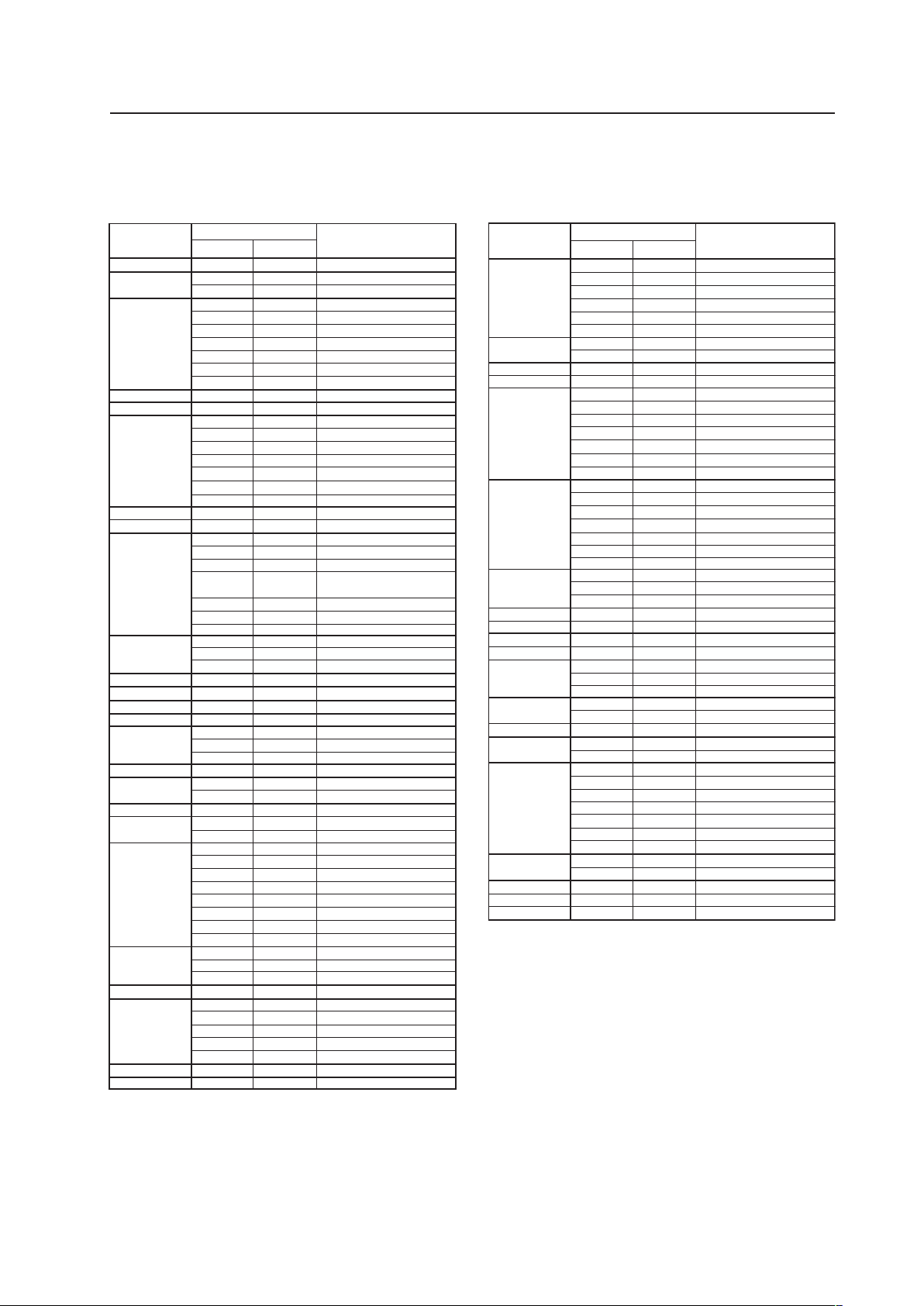
INPUT Response Signals
INPUT 1
7 PC signals supported
Resolution
(Dot x Line)
Vertical
Remark
Horizontal
70.1 Hz
70.1 Hz
85.1 Hz
60 Hz
66.7 Hz
72.8 Hz
75 Hz
85 Hz
100.4 Hz
120.4 Hz
60 Hz
60 Hz
56 Hz
60 Hz
72 Hz
75 Hz
85 Hz
99.8 Hz
120 Hz
74.6 Hz
60 Hz
60 Hz
60 Hz
70 Hz
75 Hz
(74.9 Hz)
85 Hz
100.6 Hz
56 Hz
60 Hz
70 Hz
60 Hz
59.9 Hz
60 Hz
60 Hz
60 Hz
72 Hz
75 Hz
75.1 Hz
66 Hz
76 Hz
60 Hz
60 Hz
60 Hz
60 Hz
71.2 Hz
72 Hz
75 Hz
76.1 Hz
85 Hz
100.1 Hz
60 Hz
75 Hz
85 Hz
60 Hz
60 Hz
65 Hz
70 Hz
75 Hz
85 Hz
60 Hz
60 Hz
640x400
720x400
640x480
848x480
852x480
800x600
832x624
1360x765
1024x768
1280x768
1360x768
1376x768
1280x800
1280x854
1152x864
1152x870
1152x900
1440x900
1280x960
1280x1024
1400x1050
1680x1050
1600x1200
1920x1200
1920x1200RB
Apple Macintosh 13”
I/O DATA
I/O DATA
I/O DATA
I/O DATA
I/O DATA
Apple Macintosh 16”
Work station (SGI)
( ) indicates Apple
Macintosh 19”
I/O DATA
I/O DATA
I/O DATA
CVT
PC
Apple Macintosh 21”
Sun Microsystems LO
Sun Microsystems HI
Apple Macintosh 17”
Work station (SGI)
Work station (EWS4800)
Work station (EWS4800)
Work station (HP)
Work station (SUN)
I/O DATA
CVT
CVT
31.5 kHz
31.5 kHz
37.9 kHz
31.5 kHz
35.0 kHz
37.9 kHz
37.5 kHz
43.3 kHz
51.1 kHz
61.3 kHz
31.0 kHz
31.7 kHz
35.2 kHz
37.9 kHz
48.1 kHz
46.9 kHz
53.7 kHz
63.0 kHz
75.7 kHz
49.7 kHz
47.7 kHz
48.4 kHz
49.7 kHz
56.5 kHz
60.0 kHz
(60.2 kHz)
68.7 kHz
80.5 kH
119.4 Hz
z
95.6 kHz
45.1 kHz
47.8 kHz
56.1 kHz
47.7 kHz
48.3 kHz
49.7 kHz
53.1 kHz
53.7 kHz
64.9 kHz
67.5 kHz
68.5 kHz
61.8 kHz
71.7 kHz
56.0 kHz
60.0 kHz
85 Hz 85.9 kHz
64.0 kHz
64.6 kHz
75.1 kHz
78.1 kHz
80.0 kHz
81.1 kHz
91.2 kHz
108.5 kHz
65.3 kHz
82.3 kHz
93.9 kHz
65.3 kHz
75.0 kHz
81.3 kHz
87.5 kHz
93.8 kHz
106.3 kHz
74.6 kHz
74.0 kHz
Refresh rate
INPUT 2
7 PC signals supported
8
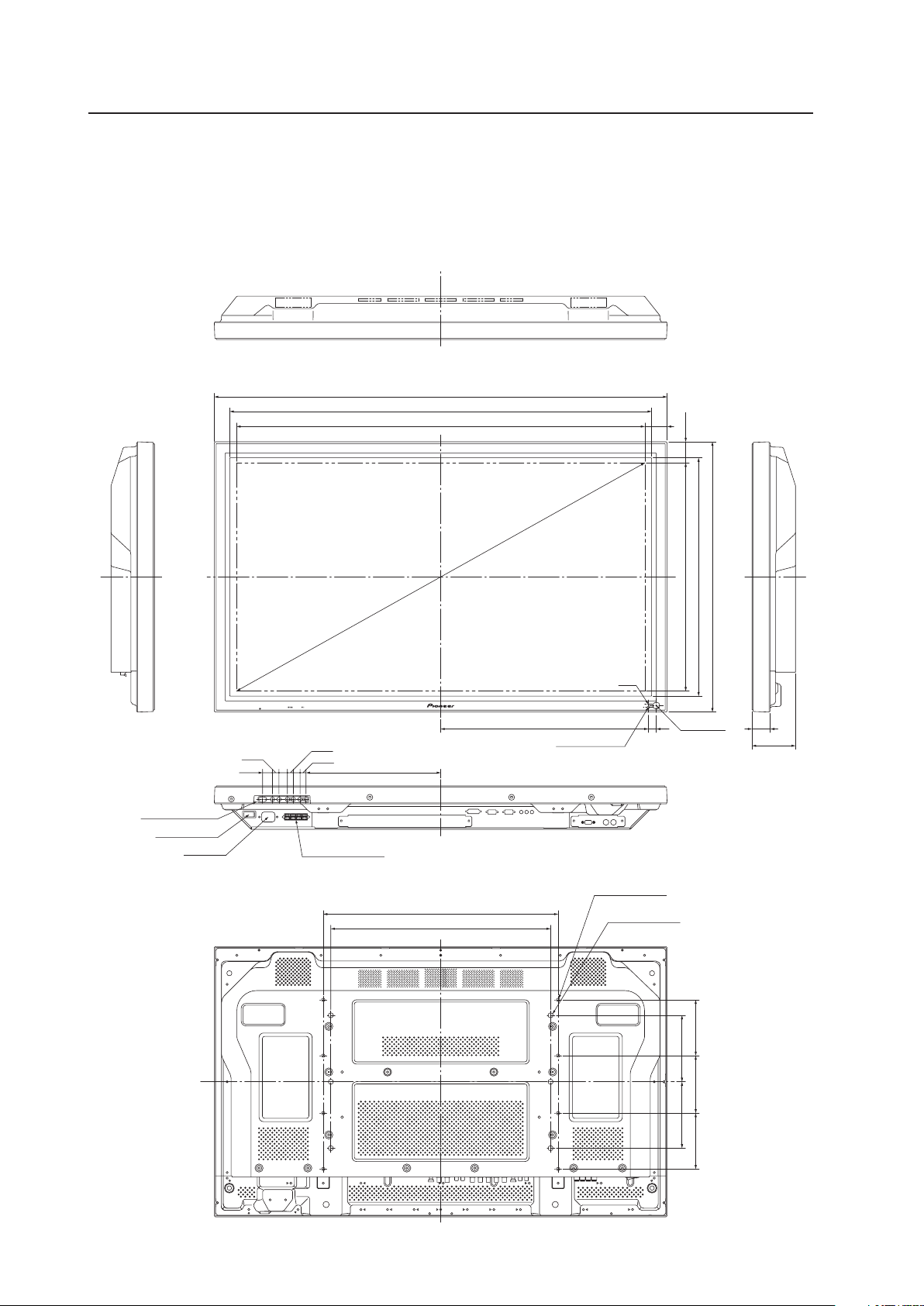
2.2 External Dimensions
WEIGHT: 30.5 kg (without stand)
MATERIAL: Front: Resin; Rear cover: Metal plate, Front protector panel: Glass
TREATMENT: Front: Paint; Rear cover: Paint (All paints are Pioneer original colors)
For packaging information, refer to “3.3.2 Unpacking” (pg. 22).
(Unit: mm)
External Dimensions
952
1022
610
538
468.6 18 40.4
98
304
13.5
15
13.5
19
14.7
22.3
SPEAKER TERMINAL
POWER BUTTON
CONTROL BUTTONS
AC INLET
BOTTOM VIEW
RIGHT SIDE VIEW
TOP VIEW
LEFT SIDE VIEW
REAR VIEW
921.6(SCREEN AREA) 50.2
515.33(SCREEN AREA) 47.34
1055.89
for mount unit
6-M8 DEPTH 18
for mount unit
8-M4 DEPTH 16
150150
126130126
530
496
Light sensor
Ambient light sensor
LED
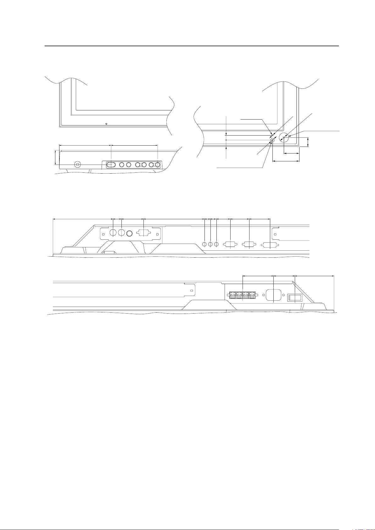
9
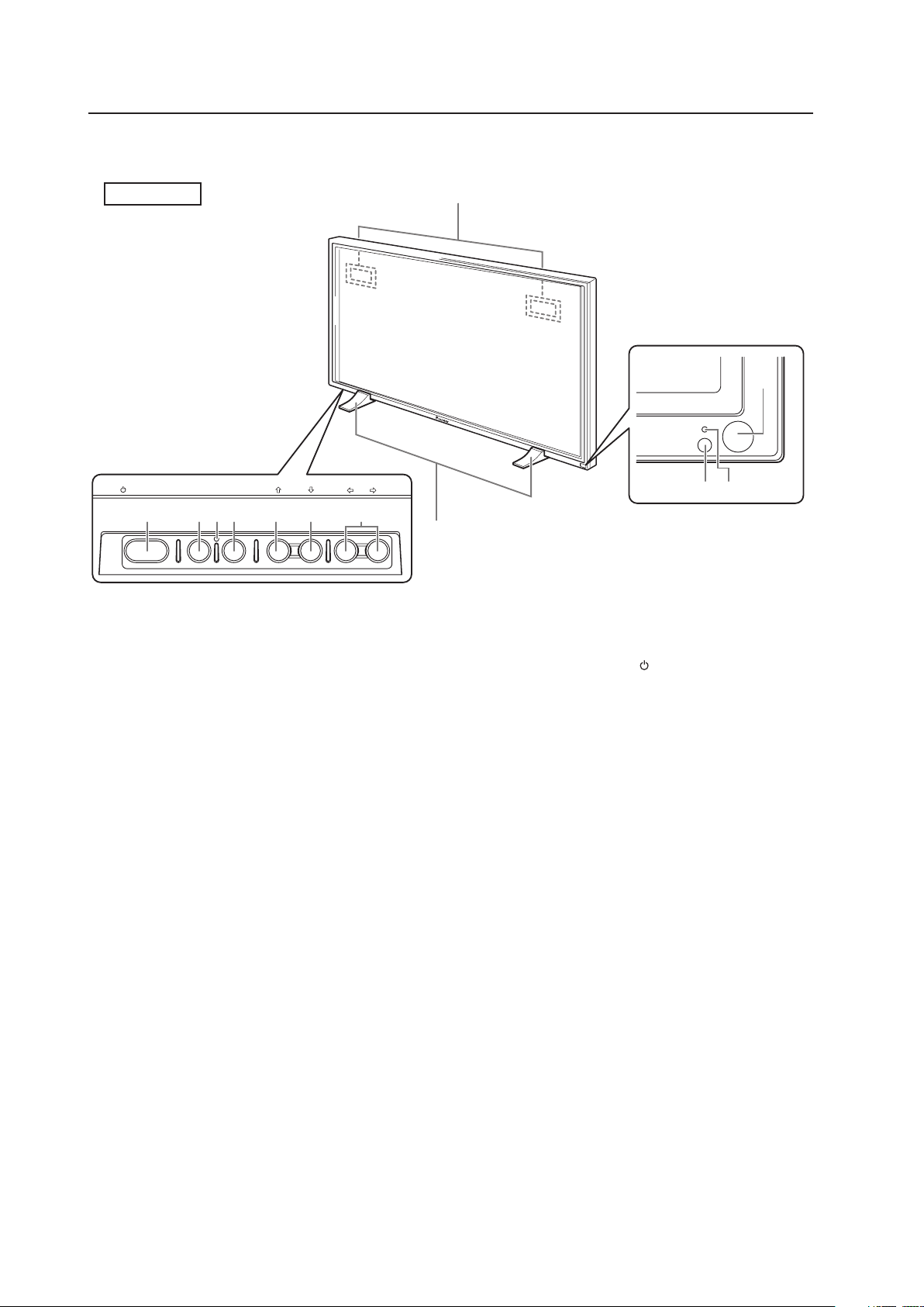
<Main Unit Operation Panel> <Light Sensor for the remote/ambient light
sensor/indicator>
External Dimensions
<PDP-425CMX/PDP-42MXE10 connection panel>
30.3
109 98
ø15.2
ø2
ø6
10.5 7.5
24.4
42.4
14.5
Indicator
Ambient light sensor
Light sensor for
the remote
(121) 17 44.5 122.6 12 12 28 38 42
62.5 43 (78.8)
10
1
5
STANDBY
ON
STANDBY/ON MENU
DISPLAY
/ SET
– VOL +INPUT SCREEN SIZE
7 8= 9 06
3
4
2
-
2.3 Controls and Connectors
Controls and Connectors
Main unit
1 Display stand
2 Remote control sensor
Point the remote control toward the remote sensor
to operate the unit.
3 Ambient light sensor
This sensor measures the level of light inside the
viewing room. To take advantage of this sensor, the
[ENGERGY SAVE] option must be set to [AUTO].
4 STANDBY/ON indicator
When the unit is ON the indicator lights green.
When flashing, the indicator denotes an error has
occurred.
The indicator blinks green once every second when
the [POWER MGT.] function is operating.
When the unit is in Standby mode the indicator
lights red.
When flashing, the indicator denotes an error has
occurred.
5 Handles
Operation panel on the main unit
6 STANDBY/ON button ( )
Press to activate the panel or place panel in the
Standby mode.
7 MENU button
Press to reveal and hide the on-screen menu.
8 DISPLAY/SET button
Press to confirm on-screen menu selections and to
change settings.
When not used by on-screen menus, this button
calls the current set status.
9 INPUT (’) button
Except when a menu screen is displayed, this
button changes the input.
0 SCREEN SIZE (‘) button
Except when a menu screen is displayed, this
button changes the screen size.
- VOL +/– (}/]) buttons
When not needed for an on-screen menu, these
buttons are used to adjust the sound volume.
= Functional lock button (concealed button)
It is used to switch between permitted/prohibited
operation of the operating panel and the remote
control and to set the input function memory.
Main unit
Operation panel on the
main unit
Main unit
11
S-VIDEO
S-VIDEO
OUT R L
R L R L R LY Pb/Cb Pr/CrIN OUT
B R VD R L
HD (H/V SYNC)
G(ON SYNC)
INP UT 3
INP UT 3 INP UT 4 INP UT 5
VIDEO
INP UT 4
INPUT 3/4 ANALOG RGB AUDIO
AUDI O
AUDI O AUDIO AUDI O
COMPONENT
VIDEO
VIDEO
INP UT 5
IN
~
^
! @
* (
#
& ) _
%
+
$
COMBINATION
IN OUT
RS-232C
AUDIO AUDIO
INPUT1
AUDIO
OUTPUT INPUT2
ANALOG RGB OUT
(D-Sub)
ANALOG RGB IN
(D-Sub)
INPUT1
DIGITAL RGB
(DVI-D)
INPUT2
2
=-09
1 3
6 7 845
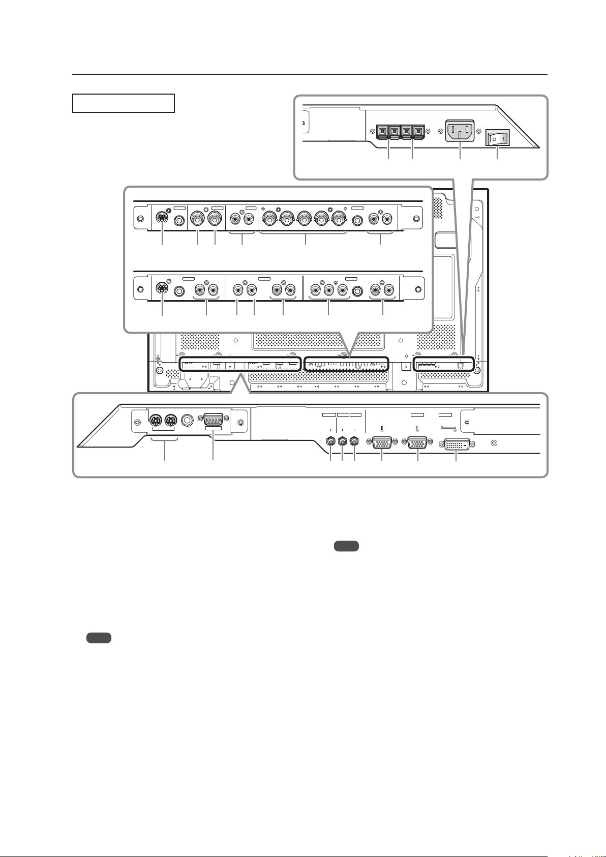
Controls and Connectors
Connection Panel
Plasma Display Section
1 COMBINATION IN/OUT
These connectors are used for Plasma Display
setup adjustments.
2 RS-232C
This connector is used for Plasma Display setup
adjustments.
3 AUDIO (OUTPUT) (Stereo mini jack)
Use this port to output the audio of the selected
source component that is connected to the Plasma
Display, to an AV amplifier or similar component.
Note
No sound is produced from the AUDIO (OUTPUT) jack
when the display is OFF or in the Standby mode.
4 AUDIO (INPUT1) (Stereo mini jack)
Use this port to obtain sound when INPUT1 is
selected. Connect this jack to the audio output
connector on the device that is connected to the
plasma panel’s INPUT1.
5 AUDIO (INPUT2) (Stereo mini jack)
Use this port to obtain sound when INPUT2 is
selected. Connect this jack to the audio output
connector on the device connected to the Plasma
Display’s INPUT2.
6 ANALOG RGB OUT (INPUT1) (mini D-sub 15 pin)
Use this connector to output the video signal to an
external monitor or other component.
Note
The video signal is not output from the ANALOG RGB OUT
(INPUT1) connector when the main power of this display is
OFF or in Standby mode.
7 ANALOG RGB IN (INPUT1) (mini D-sub 15 pin)
Use this input to connect components equipped
with RGB outputs jacks such as personal
computers. Verify that the connection corresponds
the signal output format from the connected
component.
8 DIGITAL RGB (INPUT2) (DVI-D jack)
Use this input to connect to a computer.
Connect to an AV component (HDCP supported)
equipped with DVI output connector.
9 SPEAKER (R) terminal
Use this port to connect an external right speaker.
Connect a speaker whose impedance is 6 Ω to 16 Ω.
0 SPEAKER (L) terminal
Use this port to connect an external left speaker.
Connect a speaker whose impedance is 6 Ω to 16 Ω.
When installing PDA-5003
When installing PDA-5004

12
Controls and Connectors
Video Card <PDA-5004> Section
The video card provides 3 video input connectors, 1
video output connector and 3 audio input connectors.
Consult the pages noted in parentheses ( ) for details
regarding connections to the various jacks and
connectors.
^ S-VIDEO (INPUT3) (S-video jack)
Use this jack to connect components that have an
S-video output jack such as a video deck, video
camera, laser disc player, or DVD recorder.
& AUDIO R/L (INPUT3) (RCA Pin jacks)
Use this jack to obtain sound when INPUT3 is
selected.
Connect these jacks to the component’s audio
outputs that are connected to the video card’s
INPUT3.
* VIDEO IN (INPUT4) (RCA Pin jack)
Use this jack to connect components that have a
composite video output jack such as a video deck,
video camera, laser disc player, or DVD recorder.
( VIDEO OUT (INPUT4) (RCA Pin jack)
Use this jack to output the video signal to an
external monitor or other component.
Note
The video signal is not output from the VIDEO OUT
(INPUT4) jack when the display is OFF or in the Standby
mode.
) AUDIO R/L (INPUT4) (RCA Pin jacks)
Use this jack to obtain sound when INPUT4 is
selected.
Connect these jacks to the component’s audio
outputs that are connected to the video card’s
INPUT4.
_ COMPONENT VIDEO (INPUT5) (RCA Pin jacks)
Use this jack to connect devices that have
component video output jacks such as DVD
recorders.
+ AUDIO R/L (INPUT5) (RCA Pin jacks)
Use this jack to obtain sound when INPUT5 is
selected.
Connect these jacks to the device’s audio outputs
that are connected to the video card’s INPUT5.
- AC IN
A power cable is furnished with the Plasma Display.
Connect one end of the power cable to this
connector and the other end to a standard AC
power source.
= MAIN POWER switch
Use this switch to toggle the panel’s main power
ON and OFF.
Video Card <PDA-5003> Section
The video card is provided with 3 video input
connectors, 1 video output connector and 2 audio input
connectors. Consult the pages noted in parentheses ( )
for details regarding connections to the various jacks
and connectors.
~ S-VIDEO (INPUT3) (S-video jack)
Use this jack to connect components that have an
S-video output jack such as a video deck, video
camera, laser disc player, or DVD recorder.
! VIDEO IN (INPUT4) (BNC jack)
Use this jack to connect components that have a
composite video output jack such as a video deck,
video camera, laser disc player, or DVD recorder.
@ VIDEO OUT (INPUT4) (BNC jack)
Use this jack to output the video signal to an
external monitor or other component.
Note
The video signal is not output from the VIDEO OUT
(INPUT4) jack when the display is OFF or in the Standby
mode.
# AUDIO R/L (INPUT3/4) (RCA Pin jacks)
Use this jack to obtain sound when INPUT3 or
INPUT4 is selected. Connect these jacks to the
component’s audio outputs that are connected to
the video card’s INPUT3 or INPUT4.
$ ANALOG RGB (INPUT5) (BNC jacks)
Use this jack to connect components equipped with
RGB outputs jacks such as personal computers,
external RGB decoders, or components equipped
with component output jacks such as DVD
recorders. Verify that the connection corresponds to
the signal output format from the connected
component.
% AUDIO R/L (INPUT5) (RCA Pin jacks)
Use this jack to obtain sound when INPUT5 is
selected.
Connect these jacks to the component’s audio
outputs that are connected to the video card’s
INPUT5.
13
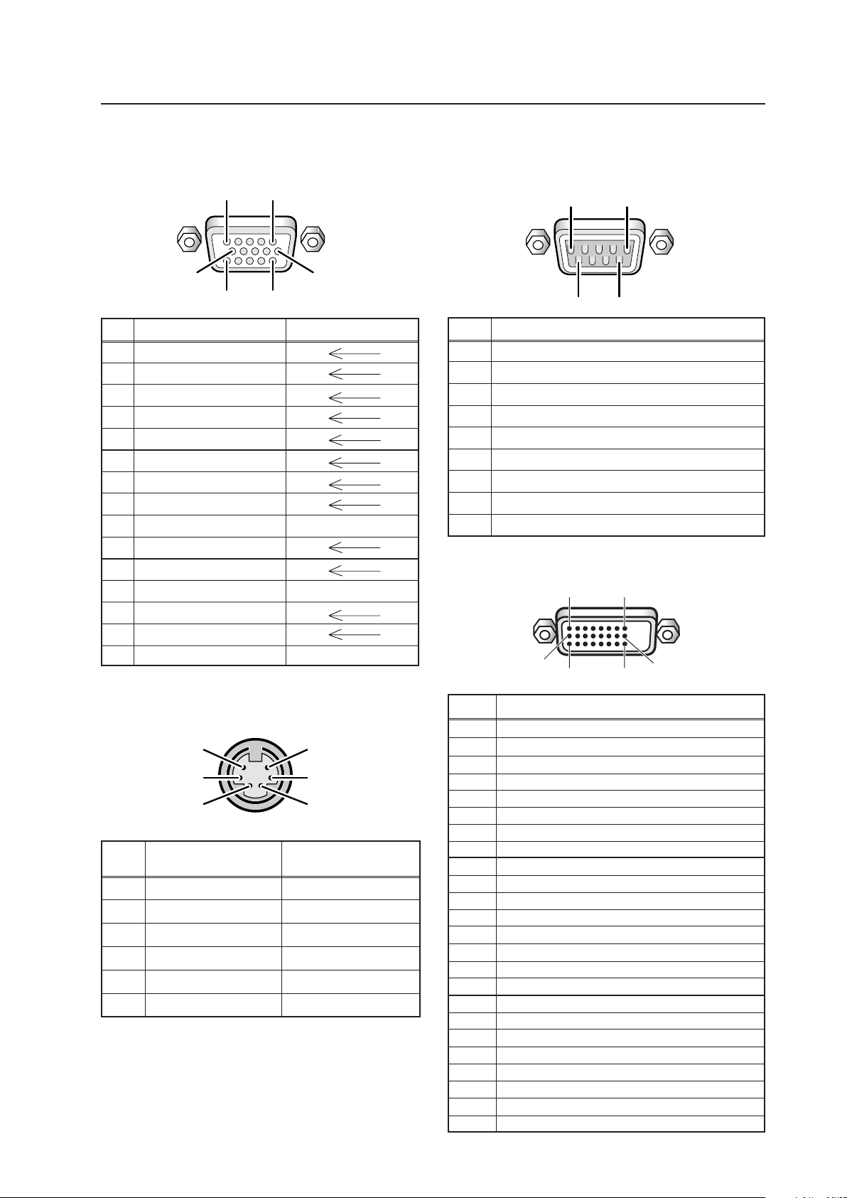
Pin layout
2.4 Pin layout
INPUT1 (Mini D-sub, 15-pin connector; female)
pin layout
Pin No.
Signal
1 NC (not connected)
2 TxD (Transmit Data)
3 RxD (Receive Data)
4 NC (not connected)
5 GND
6 NC (not connected)
7 NC (not connected)
8 RTS (Request To Send)
9 NC (not connected)
Pin No.
Combination Combination
IN OUT
1 GND GND
2 NC (not connected) NC (not connected)
3 TxD (output) RxD (input)
4 NC (not connected) NC (not connected)
5 RxD (input) TxD (output)
6 NC (not connected) NC (not connected)
Combination IN/OUT terminal pin layout
5
3
1
6
4
2
RS-232C terminal (D-sub 9-pin connector; male)
pin layout (DCE format)
Pin No.
Input Output
1 R
2 G
3 B
4 NC (not connected)
5 GND
6 GND
7 GND
8 GND
9 DDC +5V NC (not connected)
10 GND
11 NC (not connected)
12 DDC SDA NC (not connected)
13 HD or H/V SYNC
14 VD
15 DDC SCL NC (not connected)
INPUT2 (DVI-D 24 pin connector; female)
pin layout
Signal Assignment
1
2
3
4
5
6
7
8
9
10
11
12
13
14
15
16
17
18
19
20
21
22
23
24
T.M.D.S. Data2–
T.M.D.S. Data2+
T.M.D.S. Data2/4 Shield
NC (No connection)
NC (No connection)
DDC Clock
DDC Data
NC (No connection)
T.M.D.S. Data1–
T.M.D.S. Data1+
T.M.D.S. Data1/3 Shield
NC (No connection)
NC (No connection)
+5V Power
GND
Hot Plug Detect
T.M.D.S. Data0 –
T.M.D.S. Data0+
T.M.D.S. Data0/5 Shield
NC (No connection)
NC (No connection)
T.M.D.S. Clock Shield
T.M.D.S. Clock+
T.M.D.S. Clock–
Pin No.
1 2
16
2417
9
5
96
1
1
6
1115
5
10
14
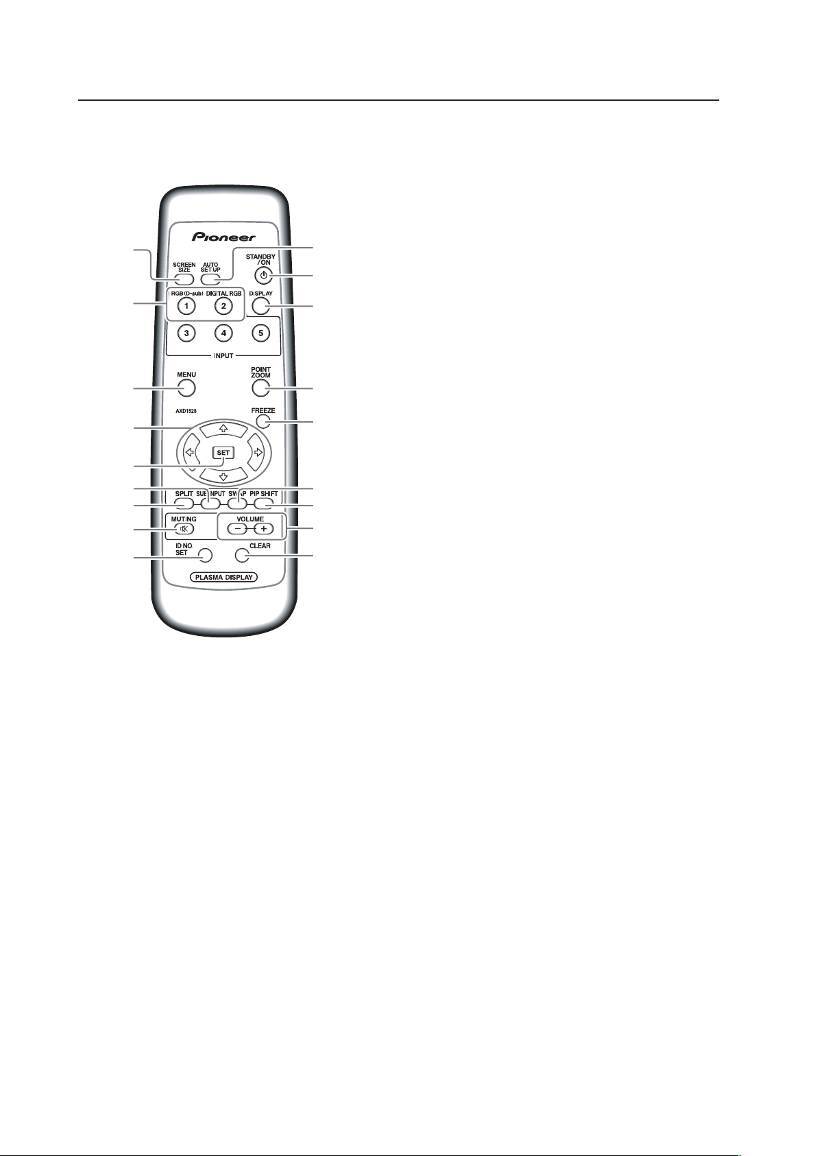
2.5 Remote Control Unit
Remote Control Unit
1 SCREEN SIZE button
Press to select the screen size.
2 INPUT buttons
Press to select the input.
3 MENU button
Press to reveal and hide the on-screen menu.
4 ADJUST (5/∞/3/2) buttons
Press to navigate menu screens and adjust various
settings on the unit.
5 SET button
Press to adjust or enter various settings on the unit.
6 SUB INPUT button
Press to change subscreen inputs during multi-
screen display.
7 SPLIT button
Press to switch to multi-screen display.
8 MUTING button
Press to mute the volume.
9 ID NO. SET button
Press to select which position the panel holds in a
video wall.
0 AUTO SET UP button
Press to automatically set the [POSITION], [CLOCK].
and [PHASE] to optimum values when using a
computer signal.
- STANDBY/ON button
Press to activate the display or place in Standby
mode.
= DISPLAY button
Press to view the unit’s current input and setup
mode.
~ POINT ZOOM button
Press to select and enlarge a portion of the screen.
! FREEZE button
Press to display a still image in the subscreen when
the memo screen function is enabled.
@ SWAP button
Press to switch between the main screen and the
subscreen during multi-screen display.
# PIP SHIFT button
Press to move the position of the subscreen when
viewing in PinP mode with multi-screen dsplay.
$ VOLUME (+/–) buttons
Press to adjust the volume.
% CLEAR button
Press to clear for program timer and ID assignment.
-
=
0
~
!
#
%
$
2
3
7
@6
8
9
1
5
4
15
Remote Control Unit Holder
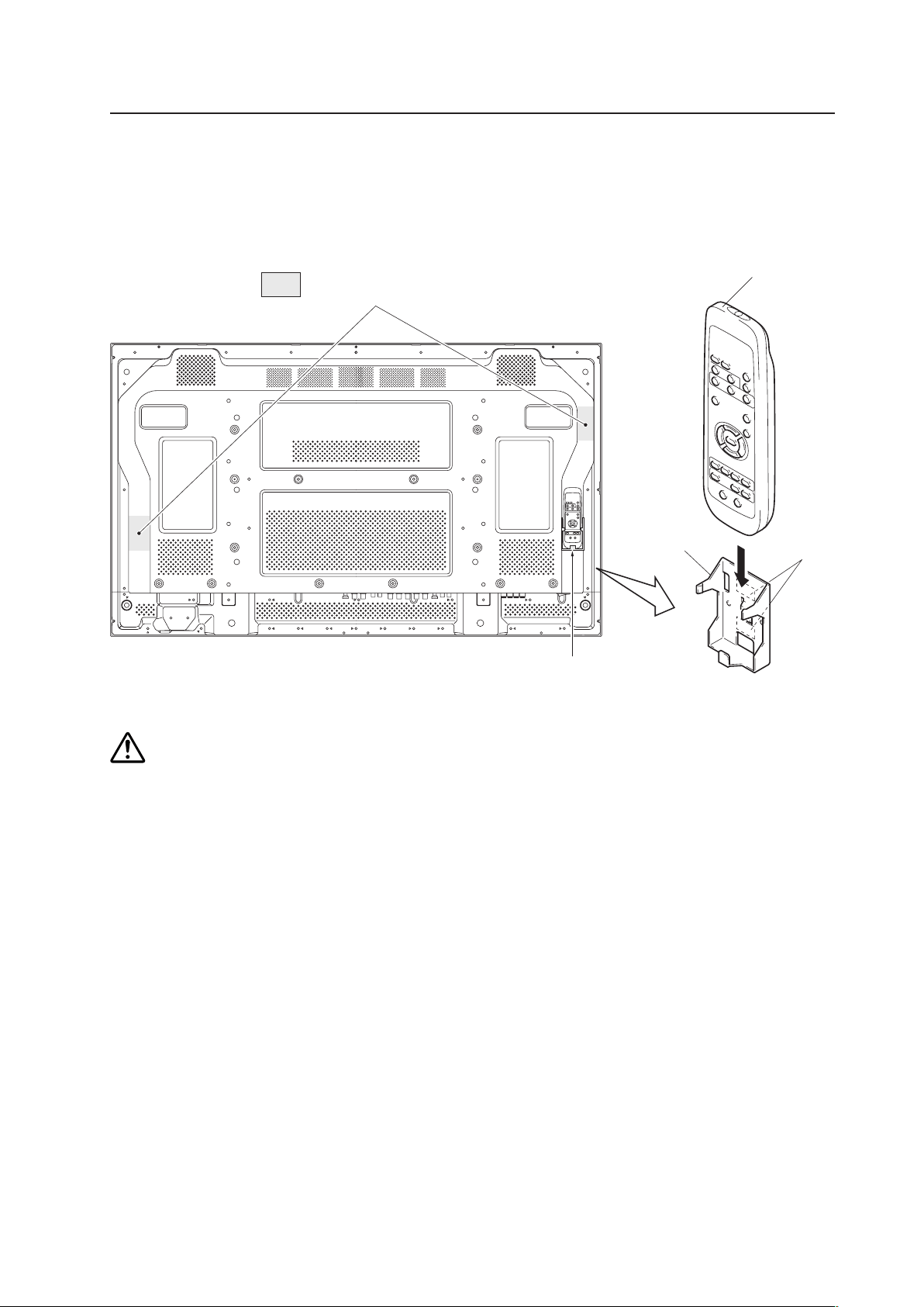
2.6 Remote Control Unit Holder
Peel the sticker covers from the lower and upper mounting tapes on the rear of the remote control holder. Attach it to
the back of the main unit or on some other fixed surface so that it will be available for storing the remote control with
the panel.
Do not block ventilation holes with the remote control holder.
Example of remote control
unit holder attachment
Area of remote control
unit holder attachment
Remote control
unit holder
Remote control unit
Upper and
lower tape
Caution
16
3.1 Installation Site Requirements
If the site requires modifications or special preparations before installing the Plasma Display or its mounting hardware,
obtain permission in advance from the building owner or building authorities. To ensure safety, it is also important to
determine the strength of the installation site with the help of an authorized building contractor.
Safety Precautions
1) Structure of the installation site
Thoroughly study the structure of the installation site before determining the most suitable installation method.
Buildings vary in structure and materials, thus the best mounting choice differs at each location. When drilling into
walls, check for internal electrical wiring and hidden pipes.
2) Weight capacity of the installation site
Select a location sufficient to support the total weight of the display and mounting hardware.
3) Flat, level surfaces
Select a flat, level surface so that the mounting hardware is parallel to the proposed mounting surface.
Install the unit so that the load is evenly distributed along the ceiling or floor, as well as on mounting hardware such as
from hang bolts.
4) Sufficient work space
Select a location with sufficient space for installation preperations. The panel mounting should be conducted by two or
more people.
5) Nearby equipment
If air conditioning ducts, lamps, etc. are located near the installation site, dust, temperatures fluctuations, humidity, and
condensation may cause problems. Please take steps to avoid this possibility.
6) Safe locations
Do not install the unit where it may be easily touched or leaned against. Avoid locations subject to high vibration or
severe impacts.
7) Lighting conditions
• Check existing lighting and sunlight angles when considering an installation layout. Bright lighting can reduce the
visibility and quality of a displayed image.
• In very bright surroundings, adjusting screen intensity may not result in perceptibly brighter images. Extreme intensity
settings can reduce a system’s service life.
8) Other installation conditions
The panel is designed for indoor use and is not suited for open-air use. Installation in locations that are even partially
exposed to the elements may lead to malfunctions or breakdown. If there is a danger of being subjected to the conditions
listed below, it is necessary to limit the exposure as much as possible.
• Water or other liquids and dust
• Temperature and humidity changes
• Salt-bearing wind
• Direct sunlight (avoid sites exposed to direct sunlight upon the display as this can degrade image quality)
Installation Site Requirements

17
9) Temperature and humidity conditions
• The installation site should meet the following conditions:
• Operating temperatures: 0 °C to 40 °C (largely depending on installation conditions)
• Operating humidity: 20 % to 80 %
• Storage temperature: –20 °C to 60 °C
• Storage humidity: 20 % to 90 %
• Operating atmospheric pressure: 800 hPa to 1114 hPa
• Storage atmospheric pressure: 700 hPa to 1114 hPa
• We discourage installing electronic products such as this unit in locations subject to high humidity. If the unit is to be
installed in a location subject to relatively high humidity, observe the following:
• Failure to install the unit in acceptable ways may result in non-warranty damages.
• Make sure the unit is grounded.
• Do not allow water or other liquids to enter the unit.
10) Prevent condensation
A primary problem during the winter is condensation forming on or in electronic equipment. Rapid temperature fluctuations
can leave water vapor inside the unit or on the screen, degrading performance. If condensation occurs, turn the unit
OFF for an hour or more then increase the room temperature gradually before turning ON the unit.
Consult Pioneer authorized dealers for assistance.
11) Power requirements
• This unit functions properly when powered at ±10 % of its rated voltage. Characteristics of power lines may effect
the voltage output. If any of the following issues occur, contact an electrician to inspect the power source.
-- Significant voltage drop between the circuit panel and the Plasma Display
-- Significant changes in voltage when switching the display power ON or OFF
• Please allow the following margin for power consumption per unit.
320 W = 320 VA
(NOTE)
When powering up the unit, the in-rush current is approximately 30 A.
• A grounded three-core power cable is used by the Plasma Display in order to maintain its functions.
Connect the power cord by inserting it into a grounded electrical outlet.
When using a different power source, use a conversion plug. Insert it into a grounded electrical outlet and securely
attach the ground wire.
• A leakage current within a value, stipulated by standards in each country, flows from an internal noise filter through
devices installed inside switching power sources such as television sets or air-conditioners. Because these currents
are added together when multiple units are connected, take steps to prevent electric shock caused by ground wires,
etc. When a leakage breaker is installed in a power distribution series, choose the leakage breaker rating that is at
least two times the total leakage current.
When many devices are connected, increase the number of leakage breakers and form branches in the wiring system.
12) Effective remote control distance
The remote control of this display receives at the following angles and distances.
• Front: 8 m
• Left-right 45°: 3 m/Left-right 30°: 7 m
• Upward 30°: 3.5 m/Upward 15°: 5 m
• Downward 30°: 5 m
If other products controlled with infrared remote controls are placed nearby, remote control function may be affected.
In such cases, move other devices further away from the display or contact a Pioneer-authorized dealer for assistance.
Depending on installation conditions, the remote control range may be reduced by infrared radiation emitted by the
screen.
The screen’s infrared intensity varies, depending upon the displayed image.
Installation Site Requirements
18
Installation Conditions
3.2 Installation Conditions
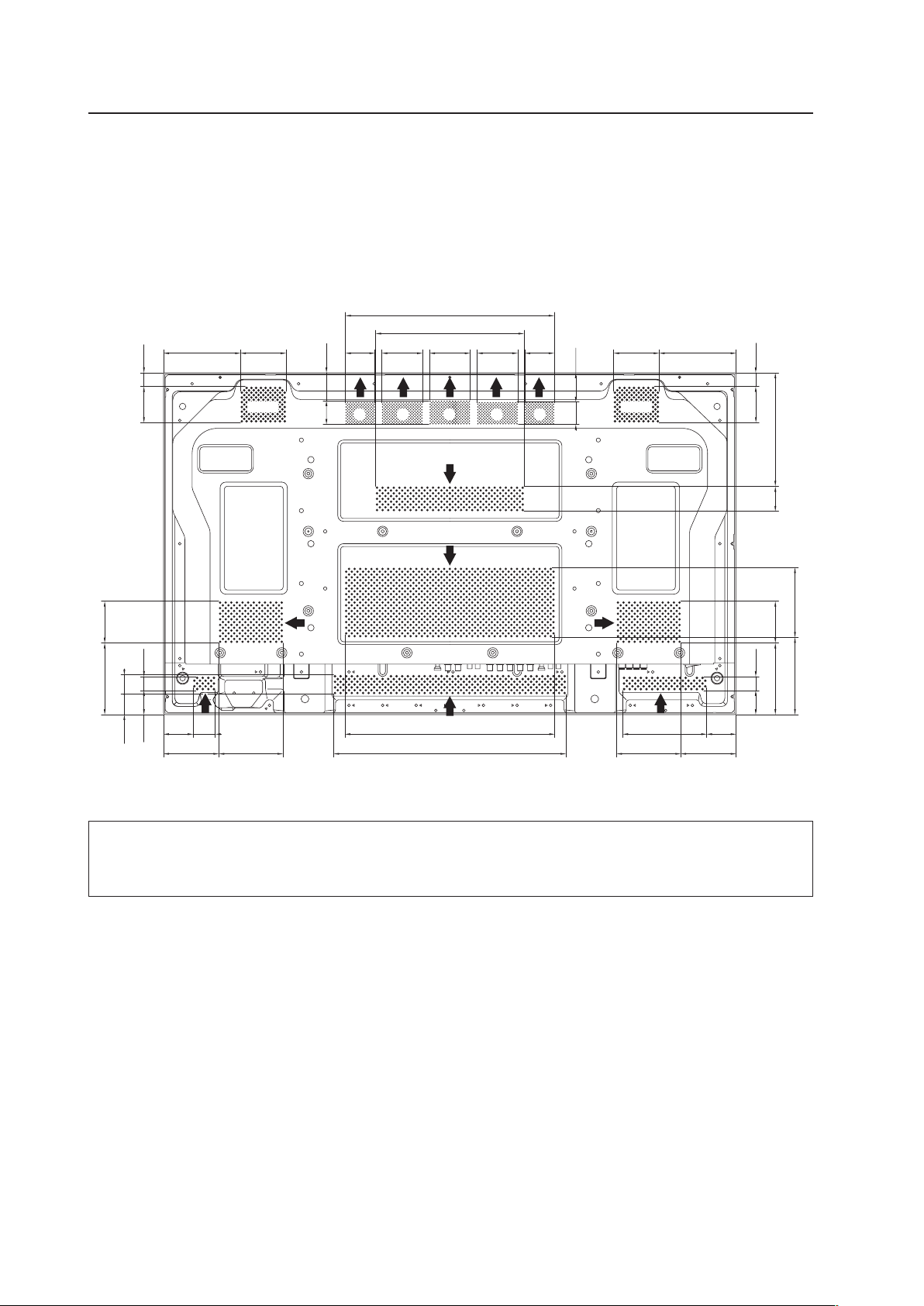
3.2.1 Heat dissipation
This unit has openings for effective ventilation. Vent locations are marked by arrows in the illustration below. The
direction of the arrows shows the direction of airflow. To allow proper dissipation of heat from the unit, do not
cover any of these openings.
(Unit : mm)
In a standard installation, two fans and part A draw hot air from the unit. All openings not assisted by fans serve as
air inlets. If the unit is hung from or embedded into a wall, special operating temperature limits and other limitations
may apply. Refer to section “3.4 Special Installation” (pg. 26) for more information.
414.5
374.5
372.4
137.381.3137.3 81.3
52.6149.8
98.8114.5
52.6 39.8
98.8 114.5
264.5
43.1 24.8
127.7 74.5
36.3 34.7
43.1 24.8
127.7 74.5
24.564.3
24.564.3
137.7
124.5
202.8
44.5
72.4 72.4 52.472.452.4
49.742.4
39.9 52.2
Fan Fan
A A A A A
19
3.2.2 Calculating heat quantity
As a courtesy to our customers, we have included the power formula for calculating air conditioning needs.
For power consumption, allow 320 W = 320 VA per unit.
Since most of the power consumed is transformed into heat, power consumption may be regarded as roughly equal to
generated heat.
1 Conversion to calories
[W] × 0.86 = [kcal/h]
Heat generated per display: 320 W × 0.86 = 275 kcal/h
2 Conversion to British Thermal Units
[W] × 3.41 = [BTU/h]
Heat generated per unit: 320 W × 3.41 = 1019 BTU/h
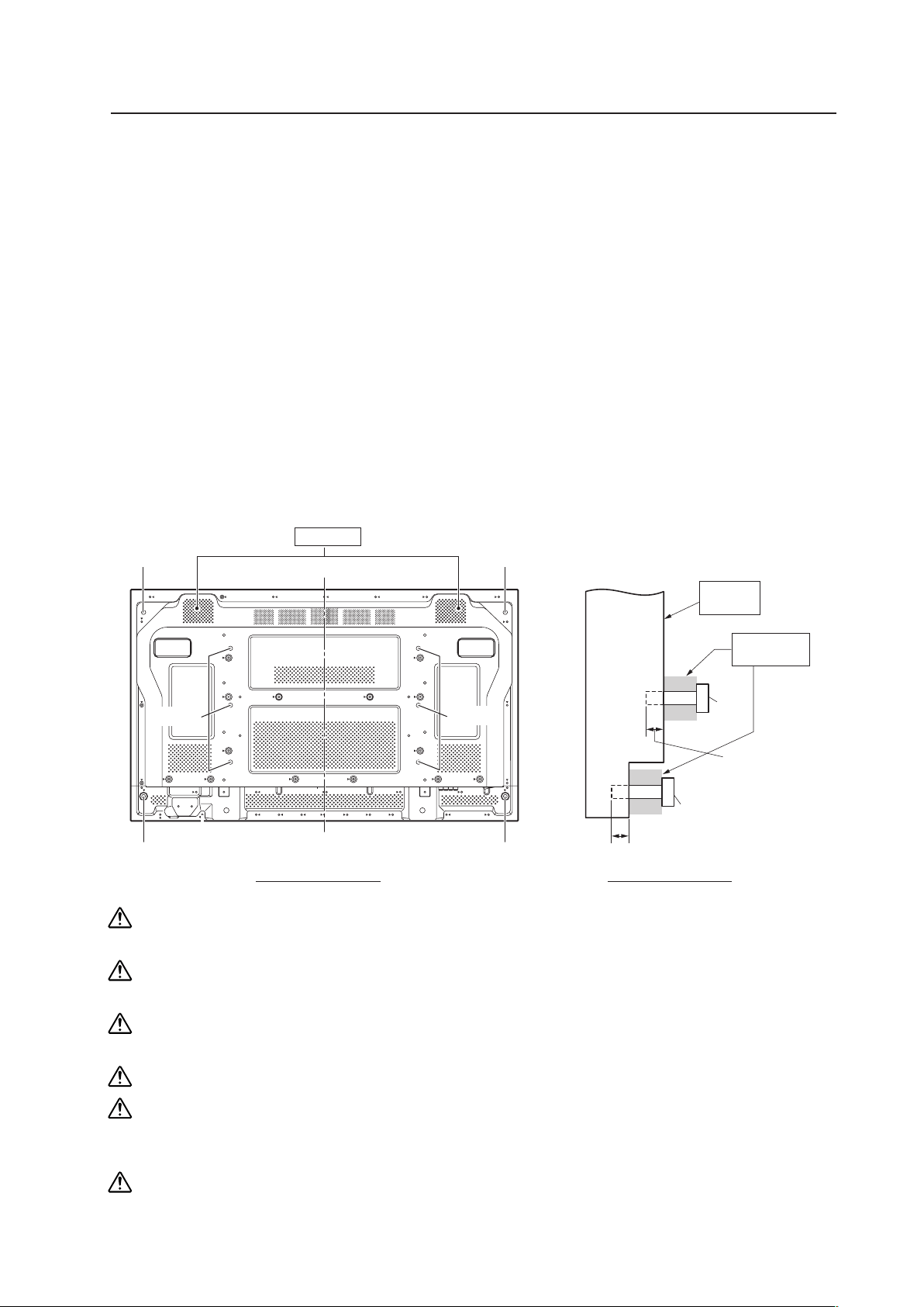
3.2.3 Product mounting holes
We recommend using mounting hardware available from Pioneer. If you use other mounting hardware, mount the
hardware to the unit using the M8-bolt holes provided in the unit. Tighten the bolts with a torque between 50 kg/cm and
80 kg/cm. Applying a torque beyond these limits may lead to internal component failure.
Locations of usable mounting holes are shown below.
Installation Conditions
Always use a minimum of 4 mounting holes that are evenly distributed on opposite sides of both the horizontal
and vertical center lines.
Use bolts that can be driven 12 mm to 18 mm into holes “a” and from 12 mm to 14 mm into holes “b” as shown
in the Side View above.
Do not block or cover vents on the rear panel.
Take precautions to prevent the walls from being soiled by the Plasma Display’s exhaust outlets.
This unit incorporates glass components. Install only on flat surfaces.
Always turn every bolt by hand two to three times then check to make sure the bolt is straight.
You may tighten using a tool but do not over-tighten the bolts.
Do not use
loctight
or similar bonding products.
Please use M8 (P=1.25) bolts. DO NOT use any other type of bolt.
The panel is attached using M8x6 or M8x4, but it can also be attached using M4x8.
For details, see the following page.
Rear view diagram Side view diagram
b hole
b hole
b hole
b hole
a holes
Center line
a Holes (6 places)
b Holes (4 places)
This unit
a hole
Bolt
Bolt
12 mm to 18 mm
12 mm to 18 mm
Vent (fan)
Attaching
surface
Installation
bracket etc...
b hole
a holes
20
Installation Conditions
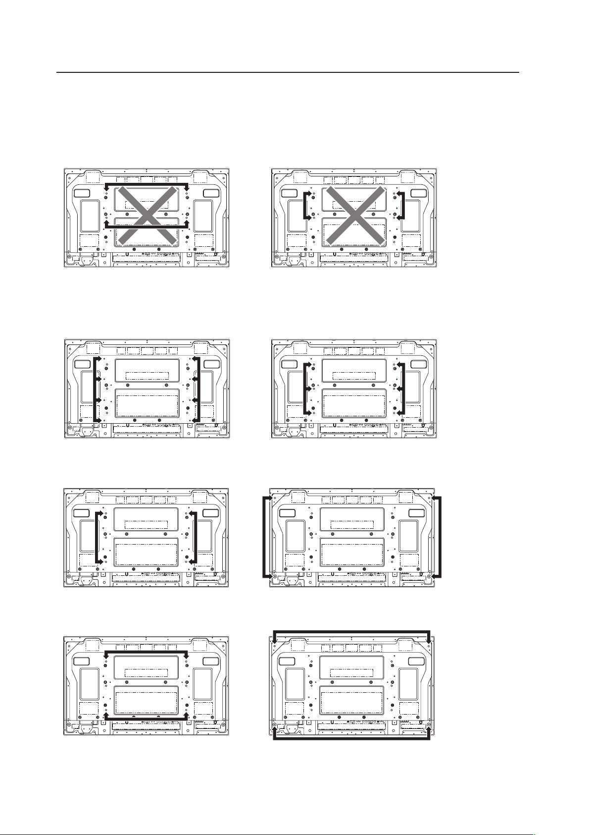
This unit is designed to be mounted using four bolt holes. For additional safety, we recommend securing it at four, six
or eight points on opposite sides of the horizontal and vertical center lines, as shown in the drawing below. Methods
shown with a large “X” must not be used.
Poor methods for securing
Suggested methods for securing
Secured at six points
*Attach using M8x6.
Secured at four points
*Attach using M8x4.
Secured at four points (with mounting hardware attached to the sides)
*Attach using M8x4.
(Take proper precautions to prevent pinching the power cord or signal cables.)
Secured at eight points
*Attach using M4x8.
21
Installation Conditions
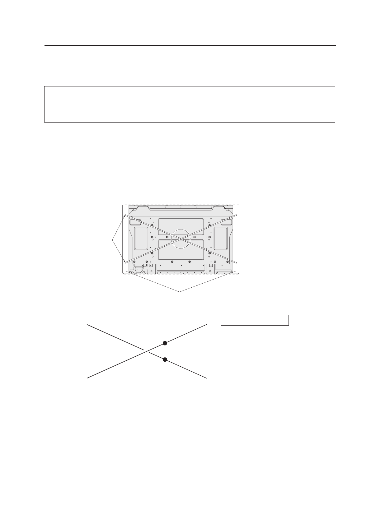
3.2.4 Mounting surface warping
The display incorporates glass. Before mounting the panel using hardware other than that provided by Pioneer, perform
the following checks to confirm that the display is free from warps exceeding 1 mm*.
Regarding the 1 mm limit:
The panel frame may have a warp of up to 3 mm. If the total warp (the warp of the frame plus the warp of the
mounting surface) exceeds 4 mm then the glass in the display may experience excessive stress. To ensure that
the total warp is less than 4 mm, verify that the warp of the mounting surface is less than 1 mm.
1 Referring to the illustration below, diagonally extend string (maximum diameter
φ
0.1- mm) through the bolt
mount openings. Strings should be completely free of slack.
2 Measure the clearance (L) between the strings where they cross.
Distortion is expressed by: [Distortion] = L × 2.
3 If L is found to be 0, pass the strings through the other bolt mount openings then repeat the measurements. Any
value of L greater than 0 indicates the presence of distortion. If the measured value in both cases is 0, the
distortion is negligible.
A
B
D
F
E
C
A
Mount bolt holes
Plasma Display Mount Surface (Mount Brackets)
String
String
Magnified view of section A
Point E is the center point of string
segment A-B.
Point F is the center point of string
segment C-D.
Clearance between points E and F = L
(Points E and F are shown displaced
for illustrative purposes).
22
Installation Procedures
Ref. No. Terms
3.3 Installation Procedures
3.3.1 Transportation precautions
• Once the shipping container is opened, transporting the unit in its packaging should be handled by two or more
people. To avoid injury or damage, do not lift the package by its packing bands.
• When transporting or storing the unit, always position it vertically - never horizontally. Horizontal transportation or
storage invalidates the product warranty.
• In transportation or storage of products in original packing, never stack more than three units high.
• For transportation or storage, observe the warnings and instructions on the upper face of the carton.
• The Plasma Display is made of glass. Please handle the panel carefully to prevent it from being damaged.
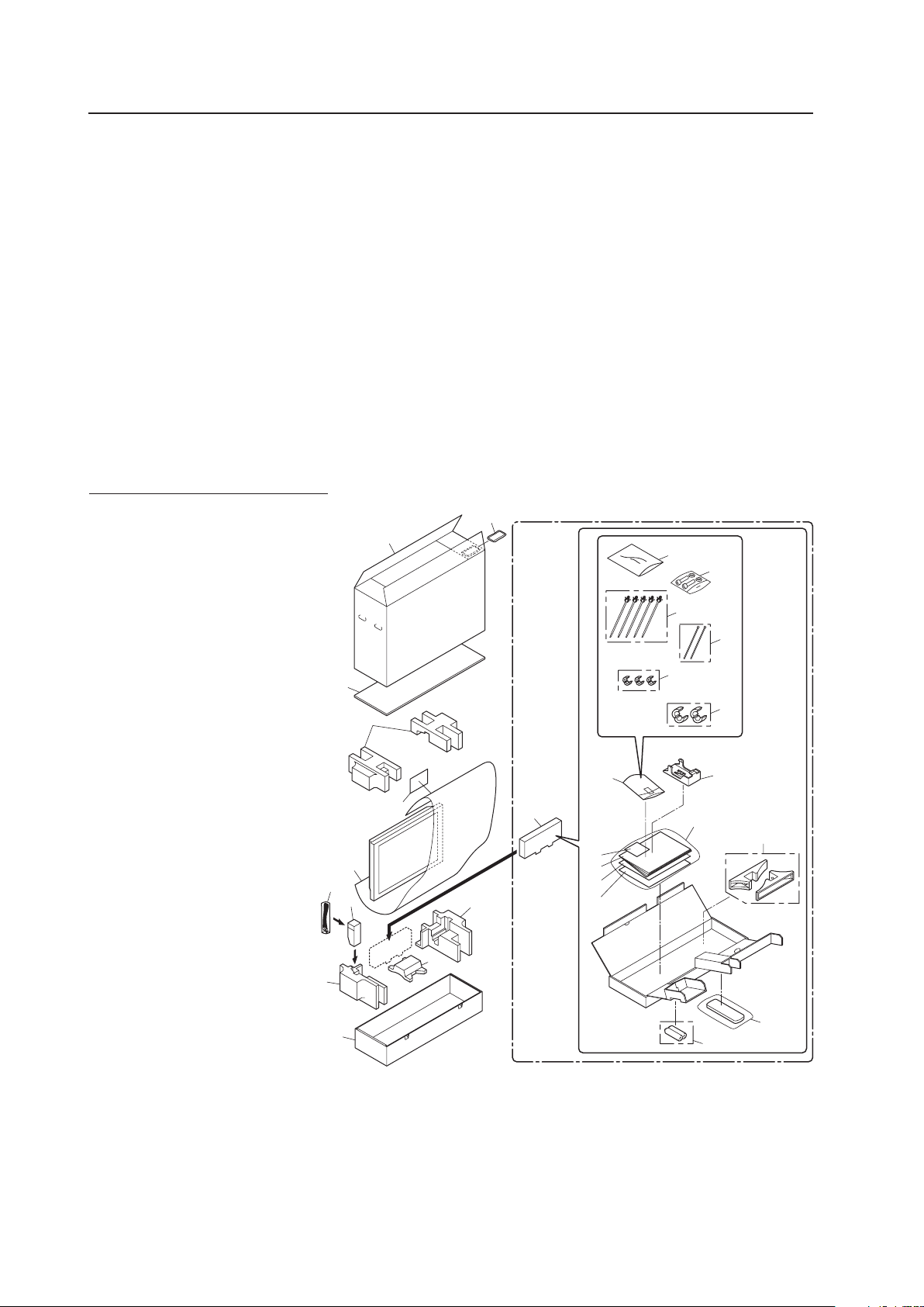
3.3.2 Unpacking
The original packing material can be re-used to safely ship the Plasma Display. When repacking, it is important to use
the material in the same way as when the unit originally shipped. Failure to pack the panel correctly can damage the
Plasma Display.
1) Packing specifications; 1177 mm (W) × 767 mm (H) × 354 mm (D), 38 kg
1 Upper Carton
2 Carton
3 Reinforce Pad
4 Pad
5 Pad
6 Mirror Mat
7 Power Cable Case
8 Accessory Case
9 Power Cord
10 Remote Control Unit
11 Dry Cell Battery (R6P, AA)
12 Remote Control Unit Holder
13 Display Stand
14 Vinyl Bag’s Assembly
15 Wiping Cloth
16 Operating Instructions
17 Warranty Card Vinyl Pouch
18 Caution Sheet
19 Caution Sheet
20 Warranty Card
21 Vinyl Bag
22 Bag
23 Screw Set
24 Reuse Band
25 Nylon Binder
26 Ferrite Core (S)
27 Ferrite Core (L)
1
2
3
4
5
5
5
6
7
8
9
10
11
12
13
14
15
16
17
18
19
20
21
22
23
24
26
27
25
23
2) Unpacking procedures
1 Remove the packing bands.
2 Slowly lift and remove the upper carton.
3 Lift and remove the carton cover.
4 Remove the pads.
5 Remove the accessory and power cord cases.
6 Remove the unit (requires two or more people).
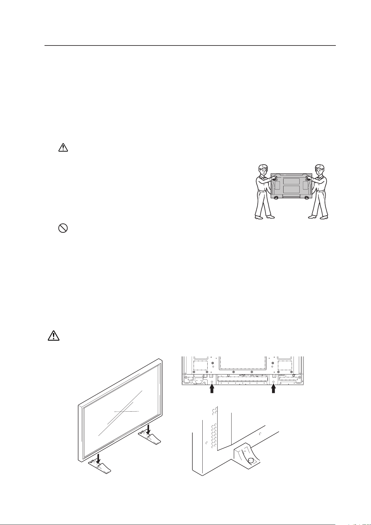
3) Transportation of the unpacked unit.
If it needs to be moved, the unit should be lifted by two or more people.
Caution
• Never move the unit by dragging it along the floor.
• Move the unit slowly, taking care to prevent scraping or striking the delicate
front protective panel.
• In order to prevent adhesion of dust, remove the protective film only after
all work and preparations for the installation site, including clean-up following
unpacking, are complete.
• When moving the display, it should always be carried by two people holding
the rear handles in the manner shown.
No!
Never attempt to move the Plasma Display by holding only one of the handles.
3.3.3 Mounting on the attachment stands (See
"
4.3 Installation of the Attachment Stand (pg. 48)
"
for instructions on permanent installation.)
Insert the stand into A and A' on the back of the main unit and anchor it with the attached washers and bolts. After
manually tightening the bolts, completely tighten them with the attached tools.
When doing this installation with the main unit on its side, align the bolts while pushing the stand.
This method should be a temporary setup pending proper installation. When installing the stand, consult “4.3 Installation
of the Attachment Stand” (pg. 48) for more information.
Placing the screen on the stands is only a temporary step before proper installation. We cannot guarantee against
damage if the display falls from someone bumping it while in the stands.
Installation Procedures
A A'

24
Installation Procedures
3.3.4 Re-packing (re-packing and re-shipping are not covered by the warranty)
If the unit needs to be re-packaged, observe the following guidelines.
• Refer to the unpacking instructions in section “3.3.2 Unpacking” (pg. 22, 23). Pack the unit by reversing the
unpacking procedure. There is a front and back to the miller mat. Place the shiny film surface facing out and the
soft surface facing in towards the display glass.
• Restore all accessories to their original locations. Secure with adhesive tape to prevent damage during
transportation.
• Do not re-package and ship if the packing material is damaged.
3.3.5 Wiring
1) Connecting the power cable
• Refer to the “ Power Cord Connection ” section in the operating instructions.
• For power source specifications, refer to “3.1 Installation Site Requirements, Section 11) Power requirements”
(pg. 17) earlier in this document.
2) Connecting signal cables
• Refer to the operating instructions shipped with the unit for information on how to connect a PC or audio
device.
• Precautions when using long connecting signal cables
-- Use coaxial cables. For video signals use 3C-2V cables for lengths up to 15 meters and 5C-2V cables for
lengths up to 30 meters. Because computer signals are more likely to degrade than video signals, even if the
cable is shorter than 15m, the use of 5C-2V coaxial multi-cables (5BNC) is recommended. You can also
improve signal quality by minimizing cable length.
-- Video cables plugged into video inputs and outputs close to dimmers, neon signs, air-conditioning units, or
cables for wired broadcasts may occasionally corrupt images.
3) Processing wires
• For permanent or long-term installation, please select cables of the correct length and consider the entire wiring
route. This is not as important for temporary or short-term installations such as at special events.
• Arrange and secure cables so that they are not subject to pinching or physical force. For temporary installations,
securing cables with string is adequate. For permanent installations, secure by more reliable means.
25
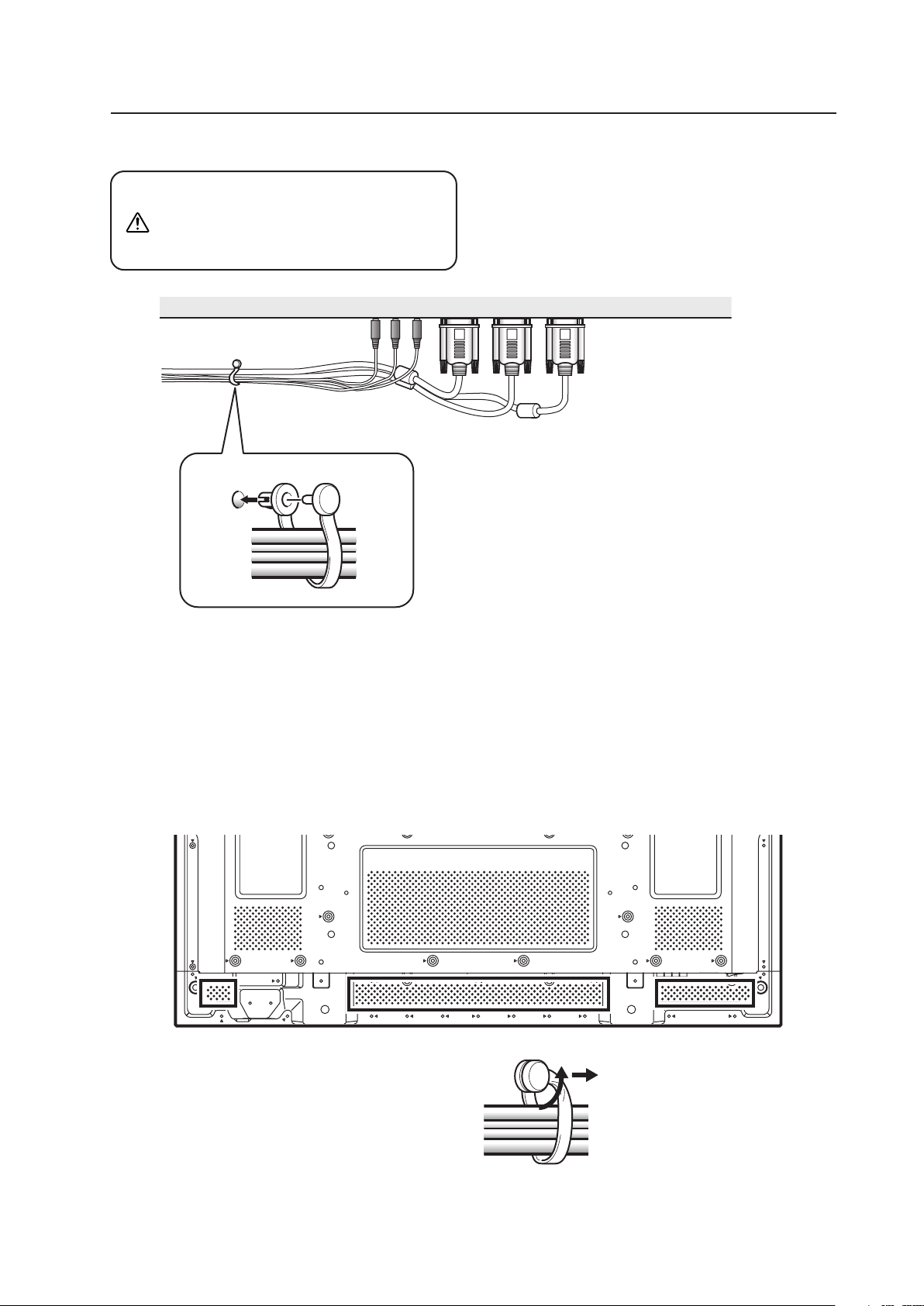
4) Arranging and securing cables with speed clamps and bead bands
Fasten cables using the supplied speed clamps.
Once speed clamps are fastened, they are
not easily removed.
Installation Procedures
Organize cables together using the provided
speed clamps.
Insert 1 into an appropriate hole on the rear of the
unit then snap 2 into the back of 1 to fix the clamp.
Speed clamps are designed to be difficult to undo
once in place. Please attach carefully.
To attach the speed clamps to the main unit
Use the holes marked with the & border shown below as
needed.
To remove speed clamps
Using pliers, twist the clamp 90° and pull outward.
In some cases, the clamp may have deteriorated over
time. Removed speed clamps may not be re-usable.
* As viewed from the rear of the display.
1
2
Note
Cables can be routed to the right or left.
* As viewed from the rear of the display.
26
Special Installation (Mounting to fittings)
3.4 Special Installation
The unit can be hung from or embedded in a wall. However, some installations impose additional limitations on
operating temperatures and other factors.
Examine installation methods and the ambient conditions for your installation site. Refer to sections “3.1 Installation
Site Requirements” (pg. 16), ”3.2 Installation Conditions” (pg. 18), and “3.3 Installation Procedures” (pg. 22) in this
manual.
Measurements discussed in this manual assume the following conditions:
• A 100 % white input is supplied.
• Sufficient aging has been completed.
Make all measurements under identical conditions. The aging period required for correct measurement
is about two and a half hours, depending on the time available at the installation site.
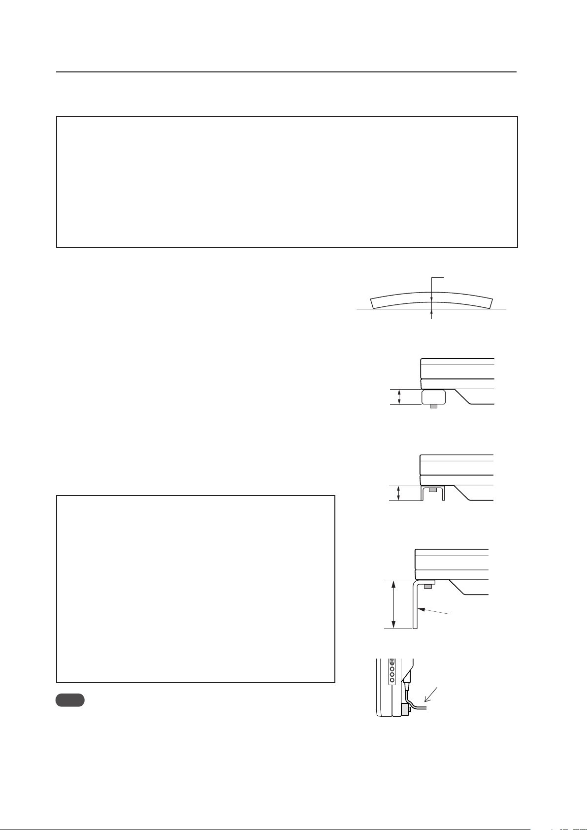
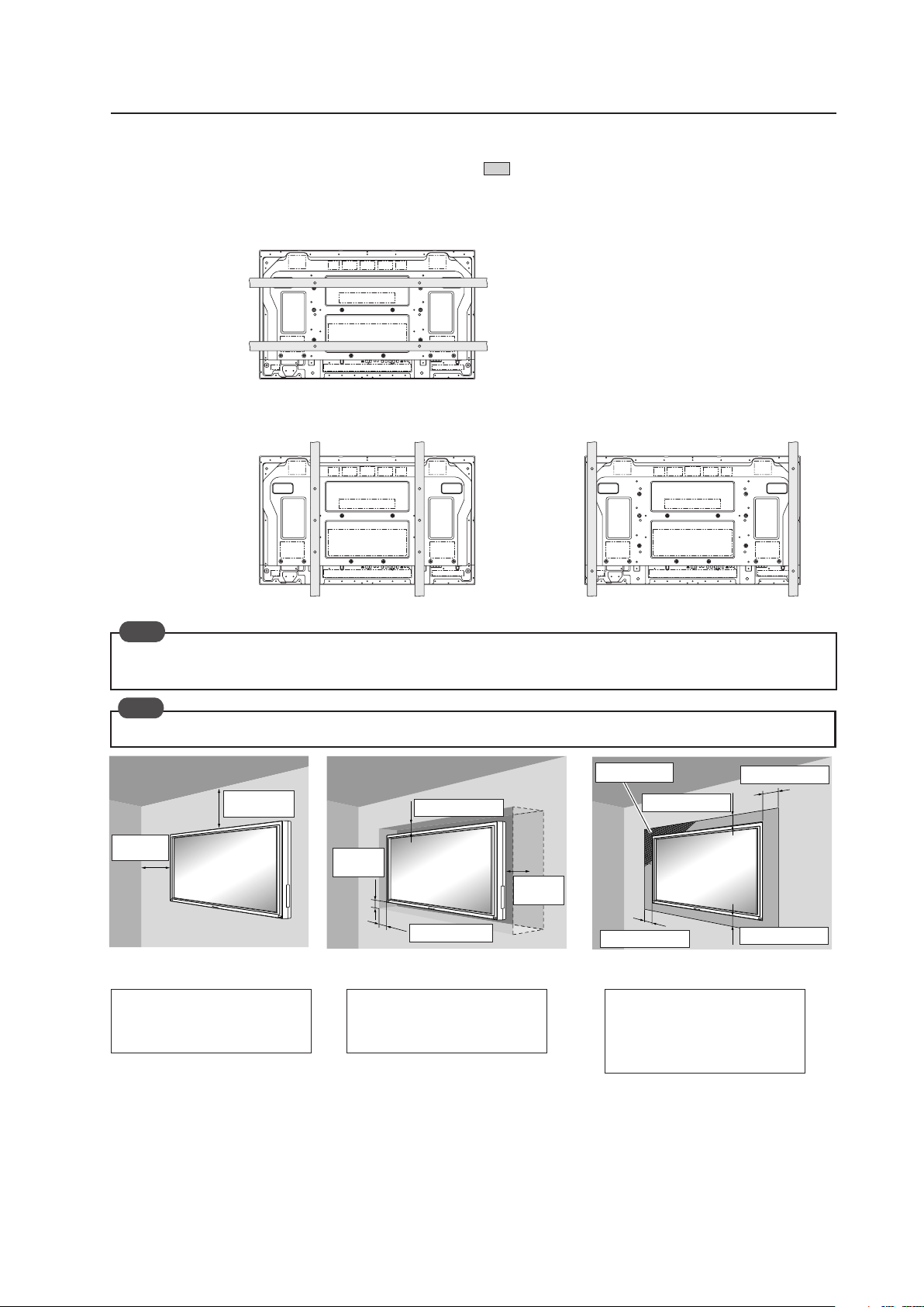
3.4.1 Mounting to fittings
Observe the following guidelines when mounting the unit to fittings.
Notes 2 to 8 apply to all cases of mounting to fittings.
1 Remove any objects from around the panel within a distance of
300 mm.
2 Any unit deformation/warping occurring as a result of installation
should be less than 4 mm.
3 Never block or cover vents or other openings aside from those
shown as blocked in the illustrations on the following page.
4 The fittings should have a thickness of less than 20 mm.
(This limit does NOT apply to fitting in examples 1, 3, 5, and 6 on
the following page.)
5 L-shaped fittings should have a thickness of less than 100 mm.
6 The strength of the fittings should be adequate to bear the weight
of the display.
7 Take precautions to avoid sharply bending the power cable.
8 If necessary, remove the handles. When reinstalling the handles,
completely tighten the screws for safety.
✩ Operating environment for standard installation
• Ambient Temperature: 0 °C to 40 °C (examples 1 to 3)
✩ Operating environment for vertical installation
(*1, *2)
• Ambient Temperature: 0 °C to 40 °C (vertical installation:
examples 4 to 6)
✩ Operating temperatures for Upside-Down Installations
(*1, *2)
• Ambient Temperature: 0 °C to 40 °C (examples 1 to 3)
The operating temperature restrictions for the speaker system (PDP-
S44-LR) are the same regardless of whether installation is horizontal
or vertical.
*1
For this installation, set the ‘FAN CONTROL’ to ‘MAX’ as shown in “5.4.3
Adjustment and Setting in the Integrator Mode 14) Cooling Fan Control
Setting (pg. 172)”.
*2
When INPUT2 has been selected, use input compatible signal up to
1280x1024 (60 Hz) at ambient temperature condition of 0 °C to 35 °C.
Note
When a video card other than PDA-5003/PDA-5004 is used, the operating
temperature conditions given above may vary. Check the video card
operating instructions for the conditions.
Arrange the power
cable so that minimum
stress is placed on it.
Less than
100 mm
L-shaped fitting
Less than
20 mm
(No thickness limitations in examples 2
and 4 on the following page.)
Less than
20 mm
(No thickness limitations in examples 2
and 4 on the following page.)
Maximum allowable deformation/
warping is 4 mm.
4 mm MAX
27
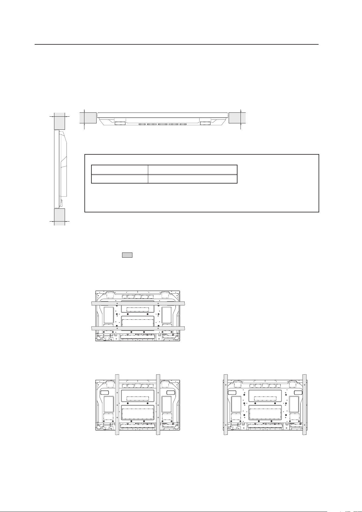
Special Installation (Mounting to fittings)
35 mm or
less
Attach so that
the fan is on
the left side
when viewed
from the rear.
Example 1
Example 2
Example 3
35 mm or
less
Example 4
Example 5
35 mm or
less
Example 6
35 mm or
less
Vertical installation
Standard installation
(In cases where top and bottom are reversed)
28
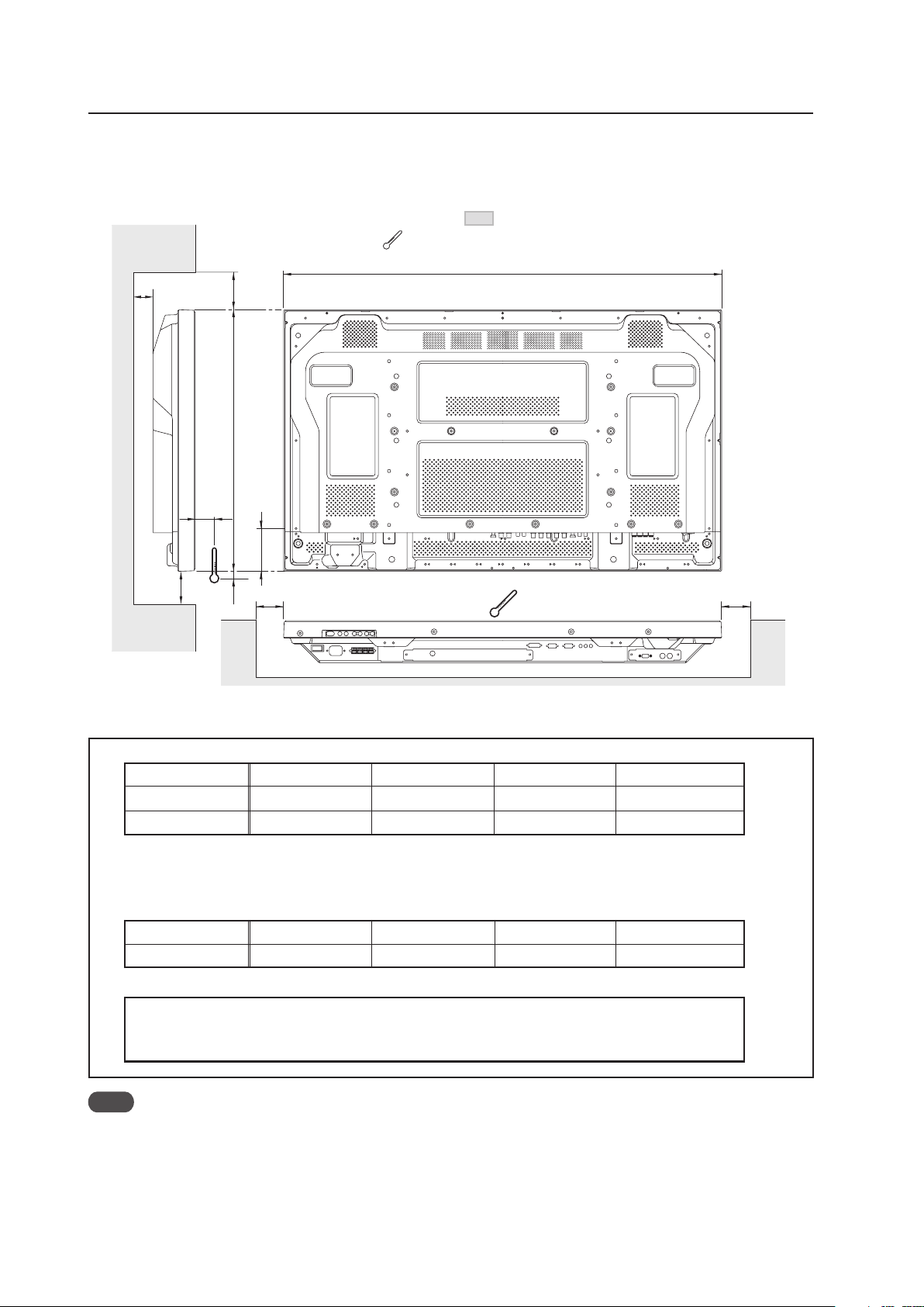
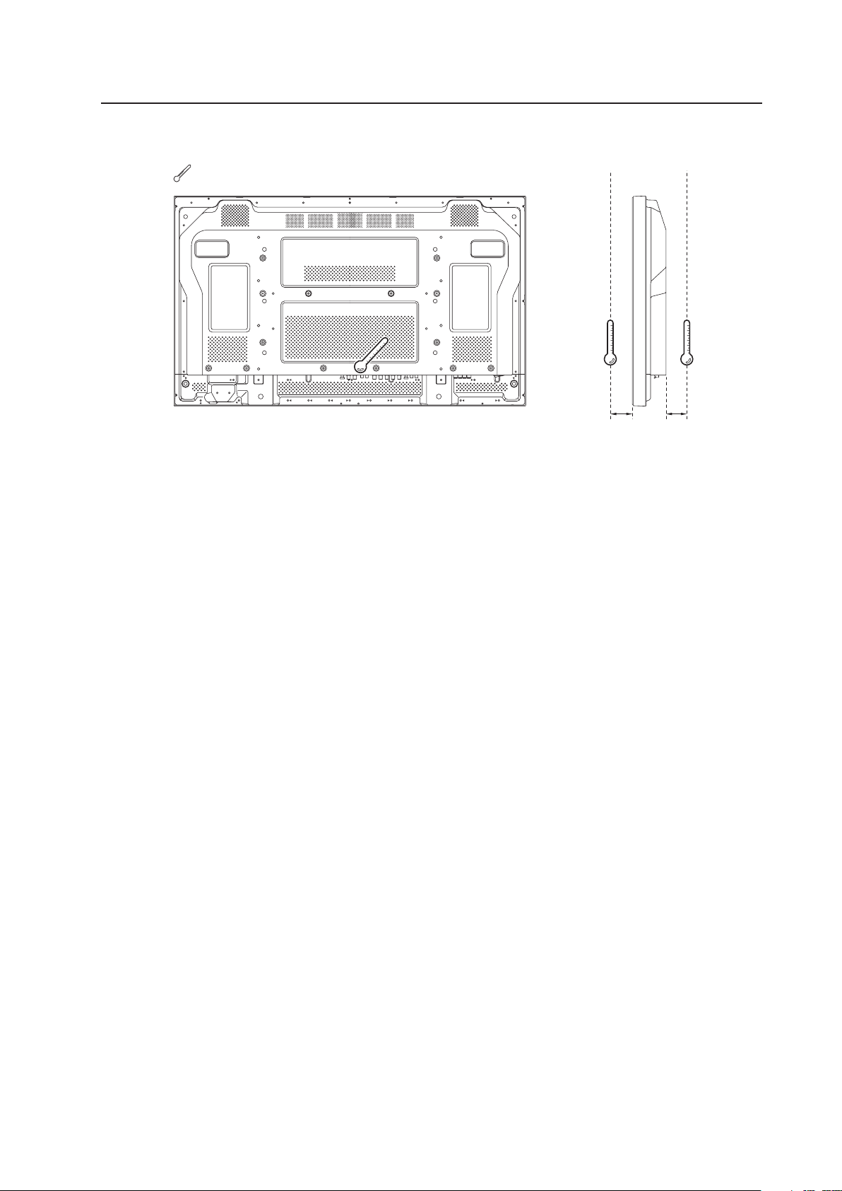
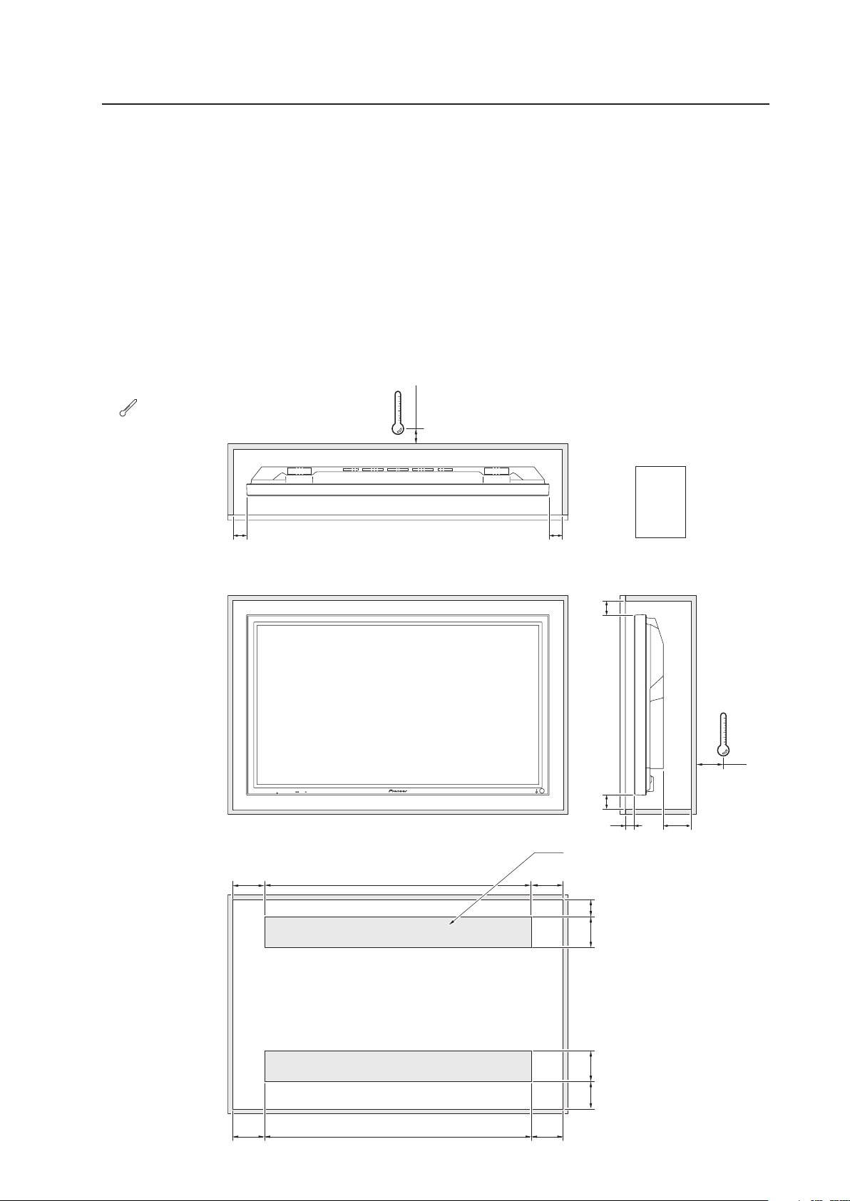
3.4.2 Hanging on the wall
Carefully read the following imformation before attempting to hang the unit on a wall. Take note of the various limitations
specified in this section. Mount the unit so that twisting, bending, or any other warping does not exceed 4 mm.
Shaded areas indicate attachment points for mounting hardware.
Special Instruction (Hanging on the wall)
Operating temperature restrictions
✩ Standard single-unit installation
Distance from wall (A) B C D Ambient temperature
50 mm or less 300 mm or more 300 mm or more 300 mm or more 0 °C to 35 °C
50 mm or more 100 mm or more 50 mm or more 50 mm or more 0 °C to 40 °C
✩ Horizontal/vertical, left/right reverse installation (Note that only Examples 2 and 3 apply in cases
where the top and bottom are reversed)
* Regardless of the distance between the Plasma Display and the wall, the unit must be installed to allow
free air flow (no obstructions within a distance of 300 mm from the unit) around the panel.
Distance from wall (A) B C D Ambient temperature
50 mm or more 300 mm or more 300 mm or more 300 mm or more 0 °C to 35°C
✩ Requirements when used with PDP-S44-LR speaker system
When installed as a single unit, all requirements are the same as those listed above for horizontal/
vertical, left/right reverse installations. However, the figures listed above indicate the distance
between the speakers and the wall.
25
90
A
B
C
D
D
1022
50
Note
Different temperature restrictions apply to the PDK-5011 and PDK-WM01. Refer to “4.6 Tilt Mount Unit” (pg. 64) and
“4.7 Wall Mount Unit” (pg. 70). For a wall-mount installation, allow adequate space (a clearance of 300 mm or more)
above, below, and to each side of the panel.
: Thermometer (temperature measurement point)
29
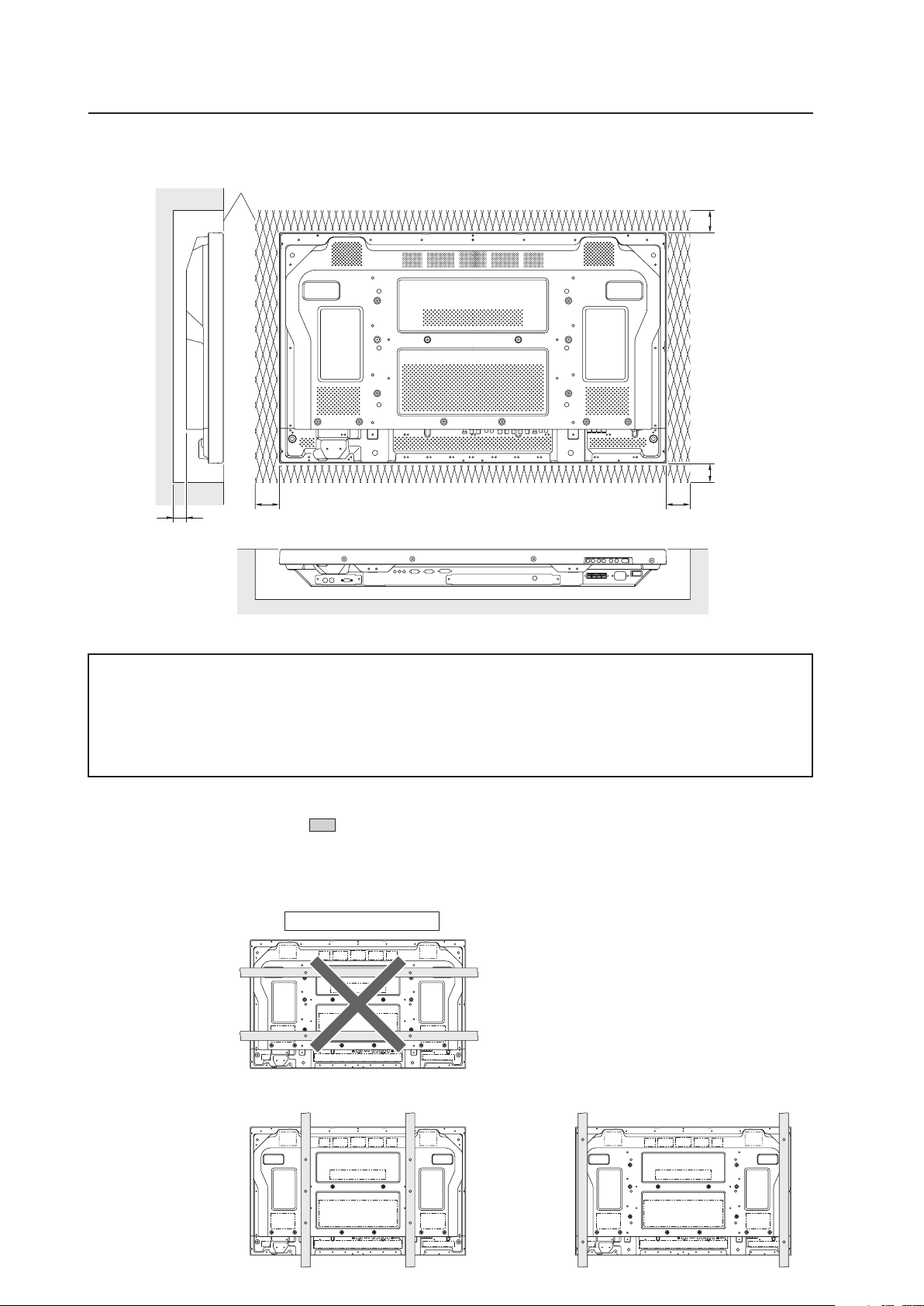
Special Installation (Hanging on the wall)
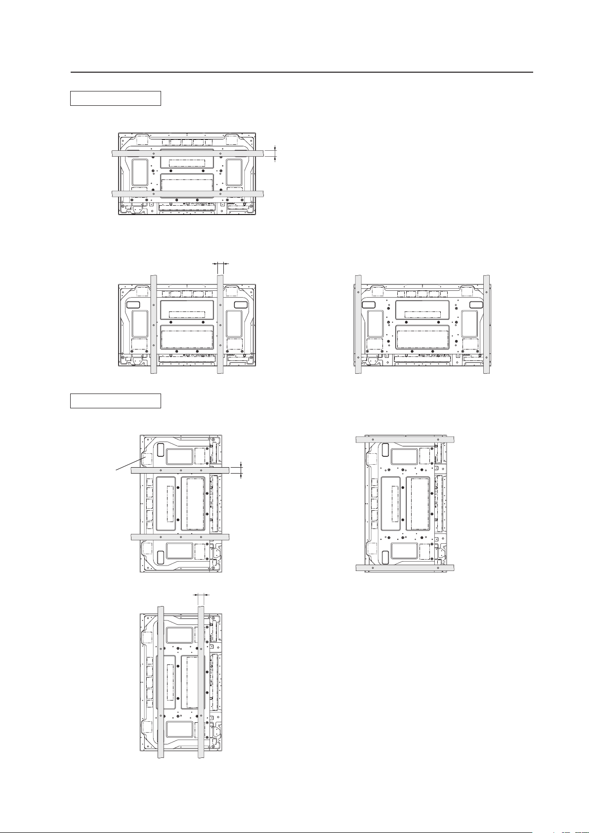
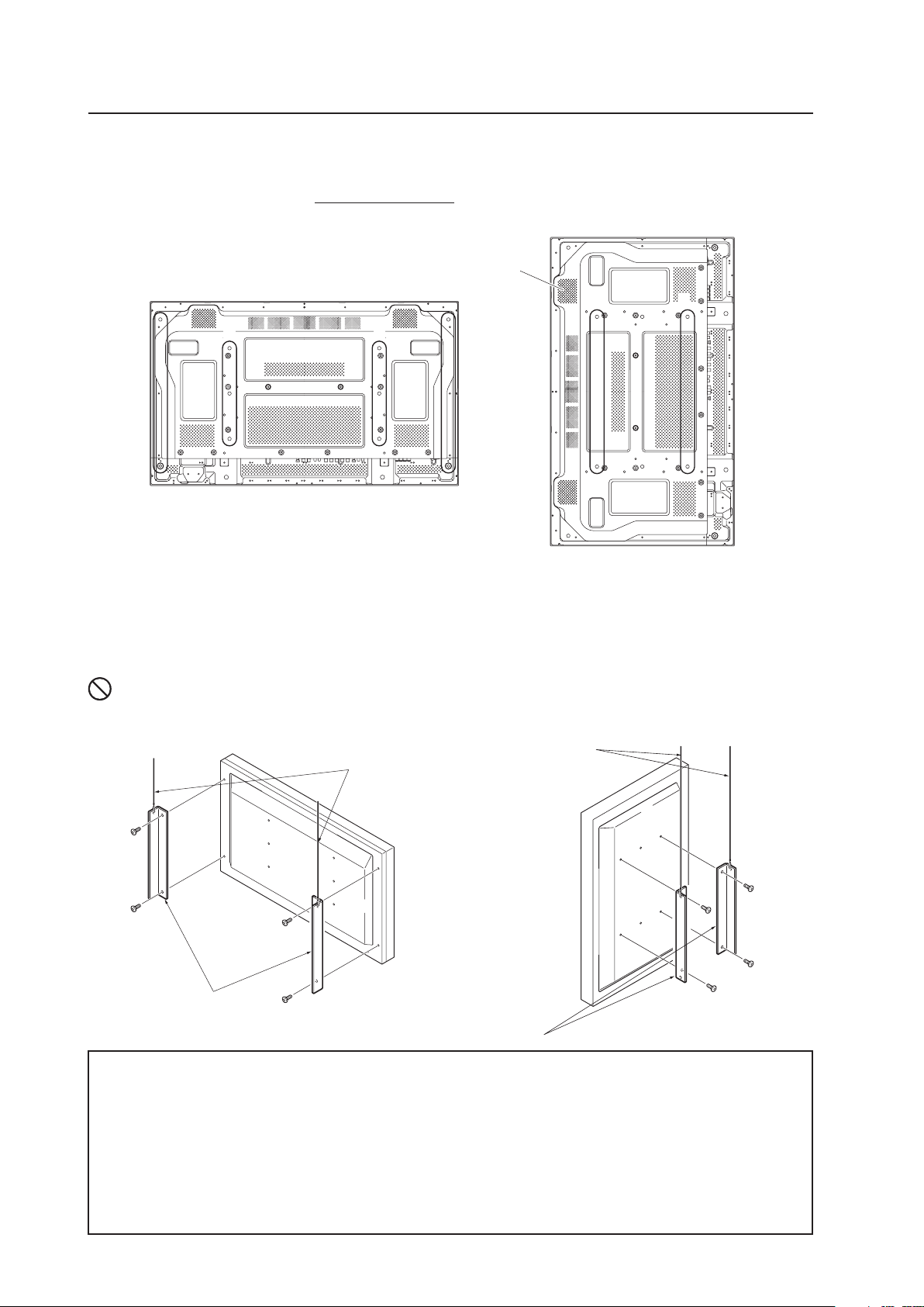
Methods of Securing: Basic methods of securing the panel to a wall are shown below. Avoid blocking or covering
areas aside from those indicated by
. The method indicated by a large “X” must not be
used. Before attaching the unit to fittings, double-check that the thickness and height of the
fittings and the number of fixing bolts is correct.
(Also refer to “3.4.1 Mounting to fittings” (pg. 26).)
Heated air is drawn from the interior of the unit by fans. Before installation, consider the heat resistance of the wall
or other surface behind the unit. Exhaust temperatures can be 30 °C higher than the outside temperature.
For wall-mounting, do not bundle the cables in a way that block vents.
Ex.: Installation requirements when
installed in wall recess
Ex.: Installation when covered with a
Panting net
Requirements :
• Free air flow (With no obstructions
within a distance of 300 mm from
the unit’s sides, top and bottom)
• Temperature of 0 °C to 35 °C
Flush-wall installation
(distance between unit and wall
less than 50 mm)
300 mm or
more
100 mm or more
50 mm or
more
Panting net
300 mm or
more
50 mm or
more
50 mm or more
Requirements :
• Free air flow (With no obstructions within
a distance of 300 mm from the unit)
around all four sides of the unit is not
necessarily required when the unit is
installed at a distance of greater than 50
millimeters away from the wall.
* However, in such cases, the unit may not
be placed behind a glass panel or any
other obstruction which would create an
enclosed space.
• Temperature of 0 °C to 40 °C
Wall-mounted installation
(distance between unit and wall
greater than 50 mm)
Requirements :
• See “3.4.3 Embedding in the wall” (pg.
30) for installation requirements.
• Temperature of 0 °C to 40 °C
Wall-embedded installation
(i.e., installation in closed space)
(distance between unit and wall
greater than 50 mm)
100 mm or more
100 mm or more
100 mm or more
100 mm or more
Note
Note
30
Special Installation (Embedding in the wall)
A
A
A
X (Front of the unit)
<Viewed from Above>
<Viewed from the Right Side>
✩ Operating Temperature Restrictions
Temperature in space X and Y
A: 0 mm to 370 mm 0 °C to 40 °C
* The same operating temperature restrictions apply to the speaker system (PDP-S44-LR).
✩ Operating Temperature Restrictions for Upside-Down Installations
* Upside-down mounting is unavailable when embedding this device in a wall.
Y (Rear of the unit)
3.4.3 Embedding in the wall
Carefully read the following imformation before trying to embed the unit in a wall. Observe all the limitations specified
below.
Be sure to mount the unit so that twisting, bending, or other deformation of the unit does not exceed 4 mm.
(1) Embedding in walls with space provided behind the unit (no obstructions within a distance of 300 mm from the
back surface of the unit).
A
Methods of Securing: Basic methods of securing are shown below. Avoid blocking or covering areas aside from those
indicated by
. The methods indicated by a large “X” must not be used.
Before attaching the unit to fittings, double-check that the thickness and height of the fittings,
and the number of bolts is correct.
(Also refer to “3.4.1 Mounting to fittings” (pg. 26).)
31
Special Installation (Embedding in the wall)
Temperature Measurement Points (Illustration for reference purposes)
• Make measurements at a distance of 50 mm from the unit without directly subjecting the thermometer to fan
exhaust.
• For spaces where temperature fluctuations are likely, gather additional measurement points for adequate data.
50 mm 50 mm
: Thermometer (temperature measurement point)
32
Cation : Due to possible heat issues, we do not recommend installing the panel in narrow, enclosed areas.
✩ Operating Temperature Restrictions
• Ambient temperature: 0 °C to 40 °C
• The same operating temperature restrictions apply to the speaker system (PDP-S44-LR).
✩ Operating Temperature Restrictions for Upside-Down Installations
* Upside-down mounting is unavailable when embedding this device in a wall.
Special Installation (Embedding in the wall)
(2) Embedding in walls with no space provided behind the unit.
Panting (Punching) net (numerical aperture 50 % or over)
100 mm or
more
100 mm or
more
100 mm or
more
100 mm or
more
50 mm or
more
Methods of Securing: Basic methods of securing are shown below. Avoid blocking or covering areas aside from those
indicated by . The methods indicated by a large “X” must not be used.
Before attaching the unit to fittings, double-check that the thickness and height of the fittings
and the number of bolts is correct.
(Also refer to “3.4.1 Mounting to fittings” (pg. 26).)
Installation is not possible
33
Special installation (When the display is put in a box)
3.4.4 When the display is put in a box
Operating this display in confined spaces is not recommended.
• If the display is to be used in a confined space, observe the following conditions shown in the drawing below:
A ≥ 50
B ≥ 50
C ≥ 10
D ≥ 50
Use a mesh with aperture efficiency of 50 % or more.
If hot air remains in the enclosed space, the temperature may rise causing a malfunction or fire. As a precaution, the
inner wall should have sufficient heat resistance or fire resistance.
✩ Usage temperature conditions (BOX air temperature)
• Ambient temperature: 0 °C to 35 °C
Rear view (the following area should be made of mesh)
A ≥ 50
B ≥ 50
C ≥ 10
D ≥ 50
A+
50 mm
A+
50 mm
A+
50 mm
B+
50 mm
B+
30 mm
100 mm
or more
100 mm
or more
Mesh with aperture efficiency
of 50 % or more
A+
50 mm
800 mm or more
800 mm or more
10 mm
10 mm
A A
BB
C D
Exhaust side Intake side
Outside air temperature
measuring point
: Thermometer
(temperature measurement point)
34
Special Installation (Ceiling suspension with wires)
When suspending from a ceiling with wire, use the brackets shown below to prevent concentrating loads on the upper
two fixing points.
For additional safety, secure the wires to separate fittings or parts of the ceiling.
Use mounting screws of material stronger than soft steel and use hexagonal bolts.
Use wires adequate for the combined weight of the panel and the weight of the support brackets.
No!
When installing the Plasma Display, DO NOT use the handles as means of hanging the display.
3.4.5 Ceiling suspension (with wires)
When suspending with wire, attach the unit either at rows A and B or at rows C and D to keep it from warping. In
addition, the unit must be attached
at four or more points, with these points distributed symmetrically on opposite
sides of the vertical and horizontal center lines.
✩ Operating environment for standard installation
• Ambient Temperature: 0 °C to 40 °C
✩ Operating environment for vertical installation
(*1, *2)
• Ambient Temperature: 0 °C to 40 °C
✩ Operating temperatures for Upside-Down Installations
(*1, *2)
• Ambient Temperature: 0 °C to 40 °
*1
For this installation, set the ‘FAN CONTROL’ to ‘MAX’ as shown in “5.4.3 Adjustment and Setting in the Integrator Mode 14)
Cooling Fan Control Setting” (pg. 172).
*2
When INPUT2 has been selected, use input compatible signal up to 1280x1024 (60 Hz) at ambient temperature condition of 0 °C
to 35 °C.
Attach so that the fan is on the left
side when viewed from the rear.
C
C
D
D
B
A
Wires
Brackets
Screws
Wires
Brackets
Screws
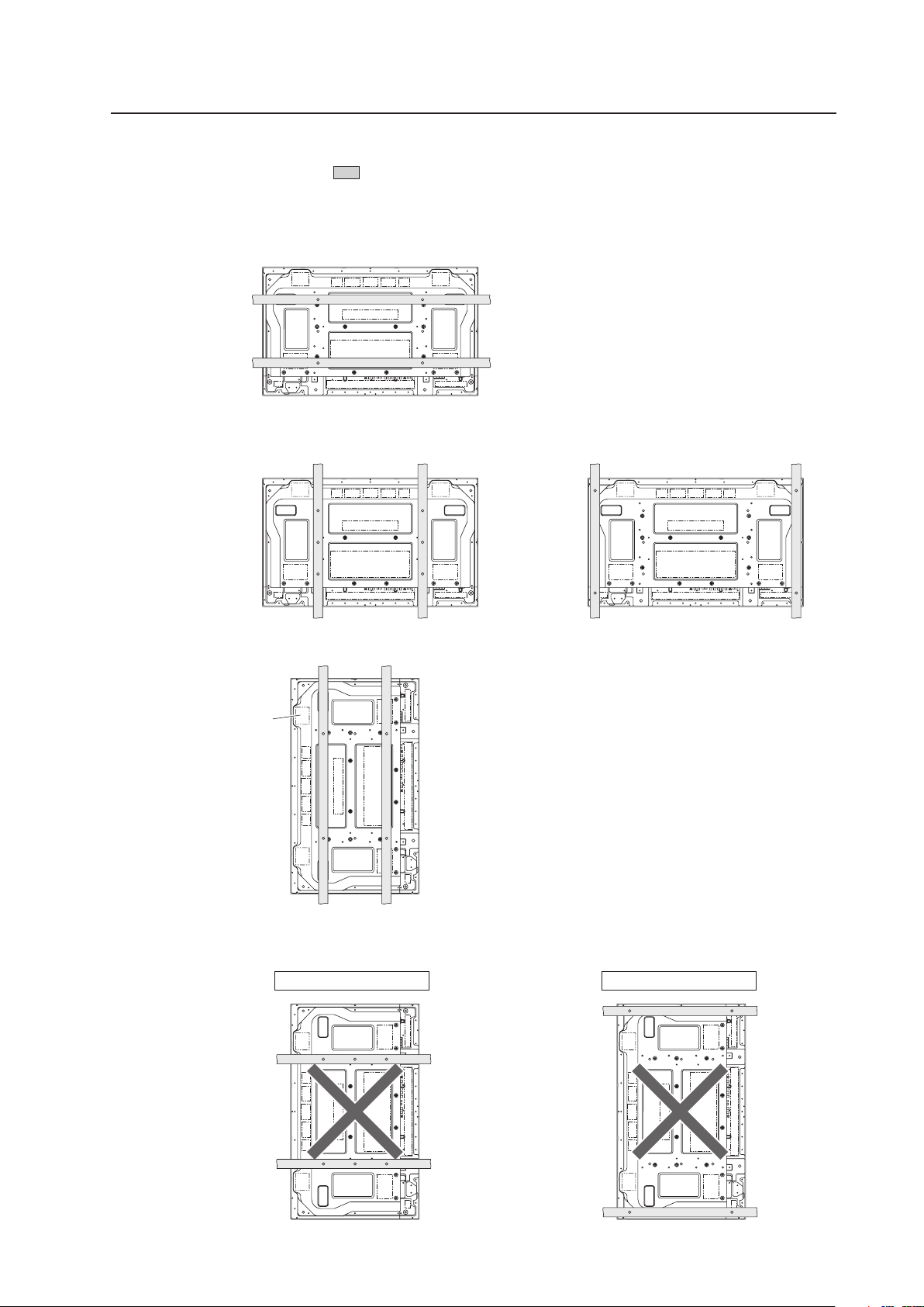
35
Special Installation (Ceiling suspension with wires)
Methods of Securing: Basic methods of securing are shown below. Avoid blocking or covering areas aside from those
indicated by . The methods indicated by a large “X” must not be used.
Before attaching the unit to fittings, double-check that the thickness and height of the fittings,
and the number of bolts is correct.
(Also refer to “3.4.1 Mounting to fittings” (pg. 26).)
Vertical suspension
Attach so that the fan is
on the left side when
viewed from the rear.
Installation is not possible
Installation is not possible
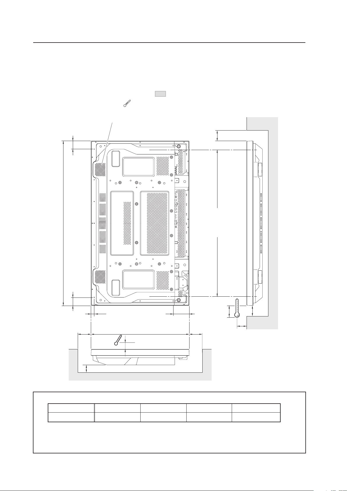
36
610
DD
A
93.4
52.552.5
C
10
1022
21.6
25
B
10
Avoid blocking or
covering this area
on the upper and
lower sides.
Attach so that the fan is on the left
side when viewed from the rear.
Special Installation (Hanging on the wall lengthwise)
3.4.6 Hanging on the wall lengthwise
Carefully read the following imformation before attempting to mount the unit on the wall. Observe the various limitations
specified below.
Be sure to mount the unit so that twisting, bending, or any other deformation does not exceed 4 mm.
Shaded areas indicate attachment points for mounting hardware.
✩ Operating Temperature Restrictions
(*1, *2)
Distance from wall (A) B C D Ambient temperature
50 mm or more 100 mm or more 50 mm or more 50 mm or more 0 °C to 35 °C
: Thermometer (temperature measurement point)
*1
For this installation, set the ‘FAN CONTROL’ to ‘MAX’ as shown in “5.4.3 Adjustment and Setting in the Integrator
Mode 14) Cooling Fan Control Setting” (pg. 172).
*2
When INPUT2 has been selected, use input compatible signal up to 1280x1024 (60 Hz) at ambient temperature
condition of 0 °C to 35 °C.

37
Special Installation (Hanging on the wall lengthwise)
Methods of Securing: Basic methods of securing are shown below. Avoid blocking or covering areas aside from those
indicated by . The method indicated by a large “X” must not be used.
Before attaching the unit to fittings, double-check that the thickness and height of the fittings
and the number of bolts is correct.
(Also refer to “3.4.1 Mounting to fittings” (pg. 26).)
Heat air is drawn from the interior of the unit by fans. Before installation, consider the heat resistance of the wall or
other surface behind the unit. Exhaust temperatures can be 30 °C higher than the outside temperature.
For wall-mounting, do not bundle the cables in a way that block vents.
Note
Note
Installation is not possible
Installation is not possible
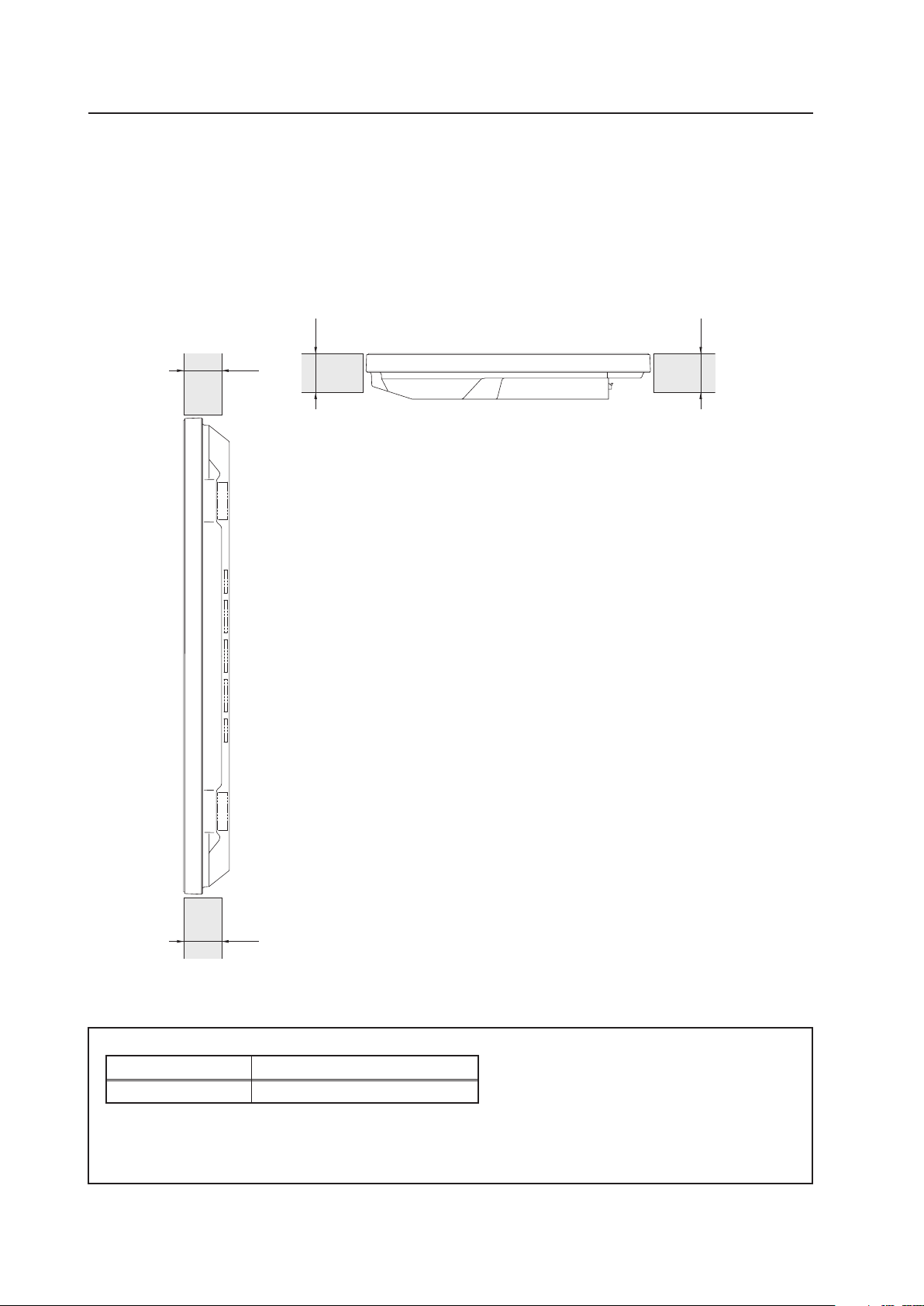
38
Special Installation (Place product upright and flush, embedded in the wall)
X (Front of the unit)
<Viewed from Above>
<Viewed from the Right Side>
✩ Operating Temperature Restrictions
(*1, *2)
Temperature in space X and Y
A: 0 mm to 370 mm 0 °C to 40 °C
Y (Rear of the unit)
3.4.7 Place product upright and flush into wall (embedding in the wall)
Carefully read the following instructions before trying to embed the unit in a wall. Observe all the limitations specified
below.
Be sure to mount the unit so that twisting, bending, or other deformation of the unit does not exceed 4 mm.
(1) Embedding in walls with space provided behind the unit (with no obstructions within a distance of 300 mm
from the back surface of the unit)
A
A
A A
*1
For this installation, set the ‘FAN CONTROL’ to ‘MAX’ as shown in “5.4.3 Adjustment and Setting in the Integrator Mode 14)
Cooling Fan Control Setting” (pg. 172).
*2
When INPUT2 has been selected, use input compatible signal up to 1280x1024 (60 Hz) at ambient temperature condition of
0 °C to 35 °C.
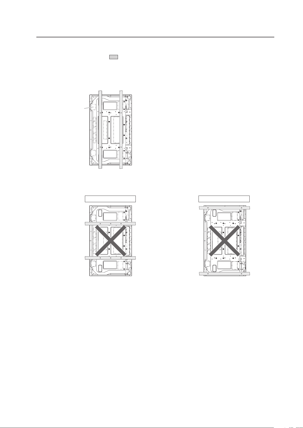
39
Special Installation (Place product upright and flush, embedded in the wall)
Methods of Securing: Basic methods of securing are shown below. Avoid blocking or covering areas aside from those
indicated by . The methods indicated by a large “X” must not be used.
Before attaching the unit to fittings, double-check that the thickness and height of the fittings
and the number of fixing bolts is correct.
(Also refer to “3.4.1 Mounting to fittings” (pg. 26).)
Attach so that the fan is
on the left side when
viewed from the rear.
Installation is not possible
Installation is not possible
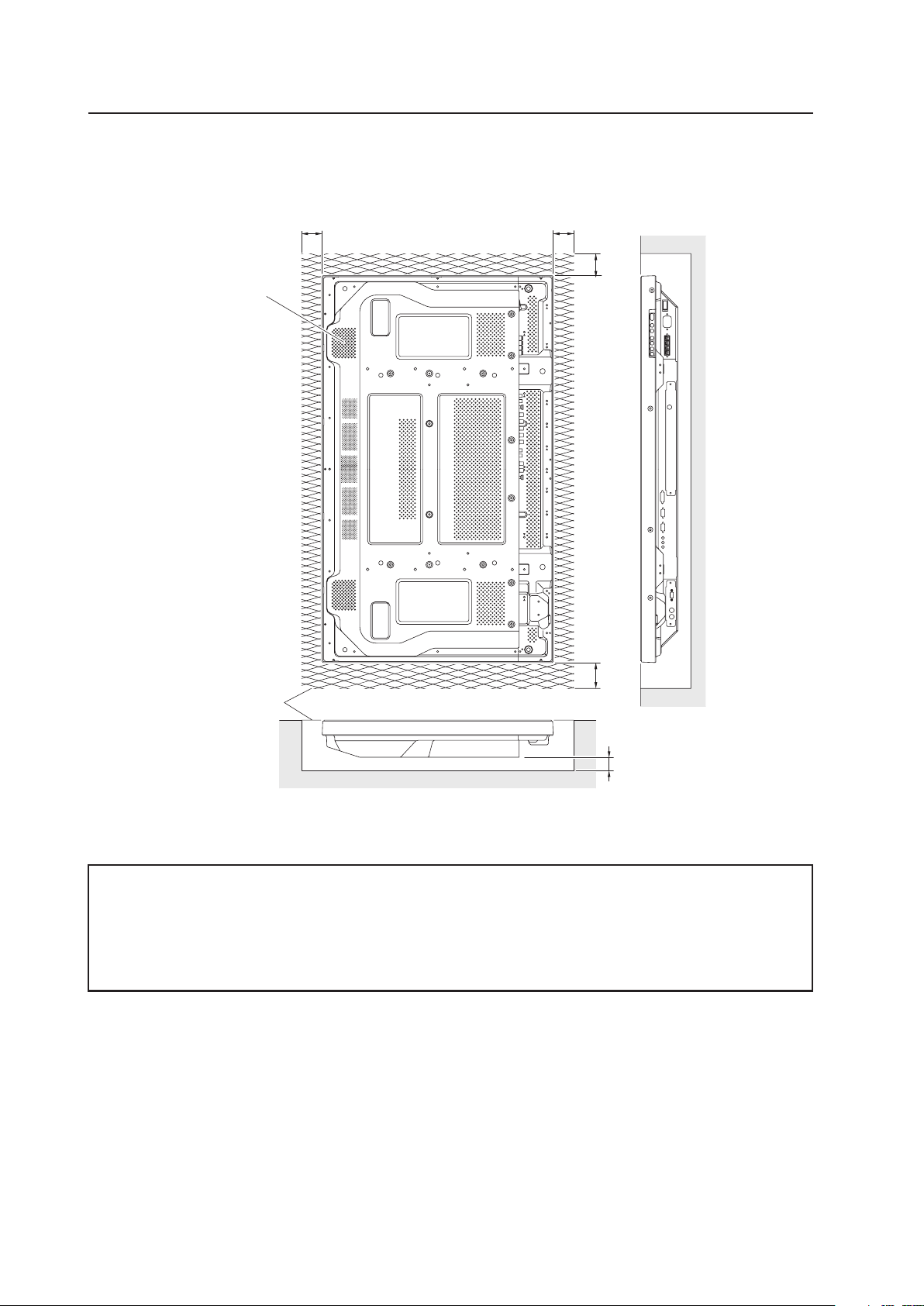
40
Cation : Due to possible heat issues, we do not recommend installing the panel in narrow, enclosed areas.
✩ Operating Temperature Restrictions
(*1, *2)
• Ambient temperature: 0 °C to 35 °C
*1
For this installation, set the ‘FAN CONTROL’ to ‘MAX’ as shown in “5.4.3 Adjustment and Setting in the Integrator Mode 14)
Cooling Fan Control Setting” (pg. 172).
*2
When INPUT2 has been selected, use input compatible signal up to 1280x1024 (60 Hz) at ambient temperature condition of 0 °C
to 35 °C.
Special Installation (Place product upright and flush, embedded in the wall)
(2) Embedding in walls with no space provided behind the unit
Panting (Punching) net
(numerical aperture 50 %
or over)
100 mm or
more
100 mm or
more
100 mm or
more
100 mm or
more
50 mm or
more
Attach so that the
fan is on the left
side when viewed
from the rear.
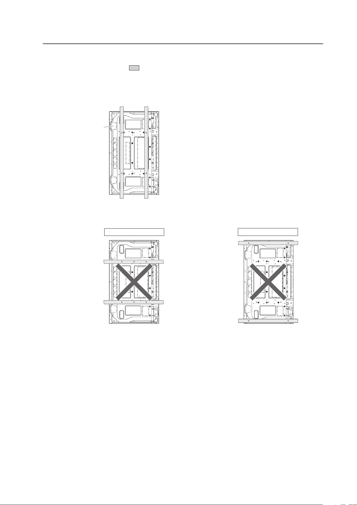
41
Special Installation (Place product upright and flush, embedded in the wall)
Methods of Securing: Basic methods of securing are shown below. Avoid blocking or covering areas aside from those
indicated by . The methods indicated by a large “X” must not be used.
Before attaching the unit to fittings, double-check that the thickness and height of the fittings
and the number of bolts is correct.
(Also refer to “3.4.1 Mounting to fittings” (pg. 26).)
Attach so that the fan is
on the left side when
viewed from the rear.
Installation is not possible
Installation is not possible
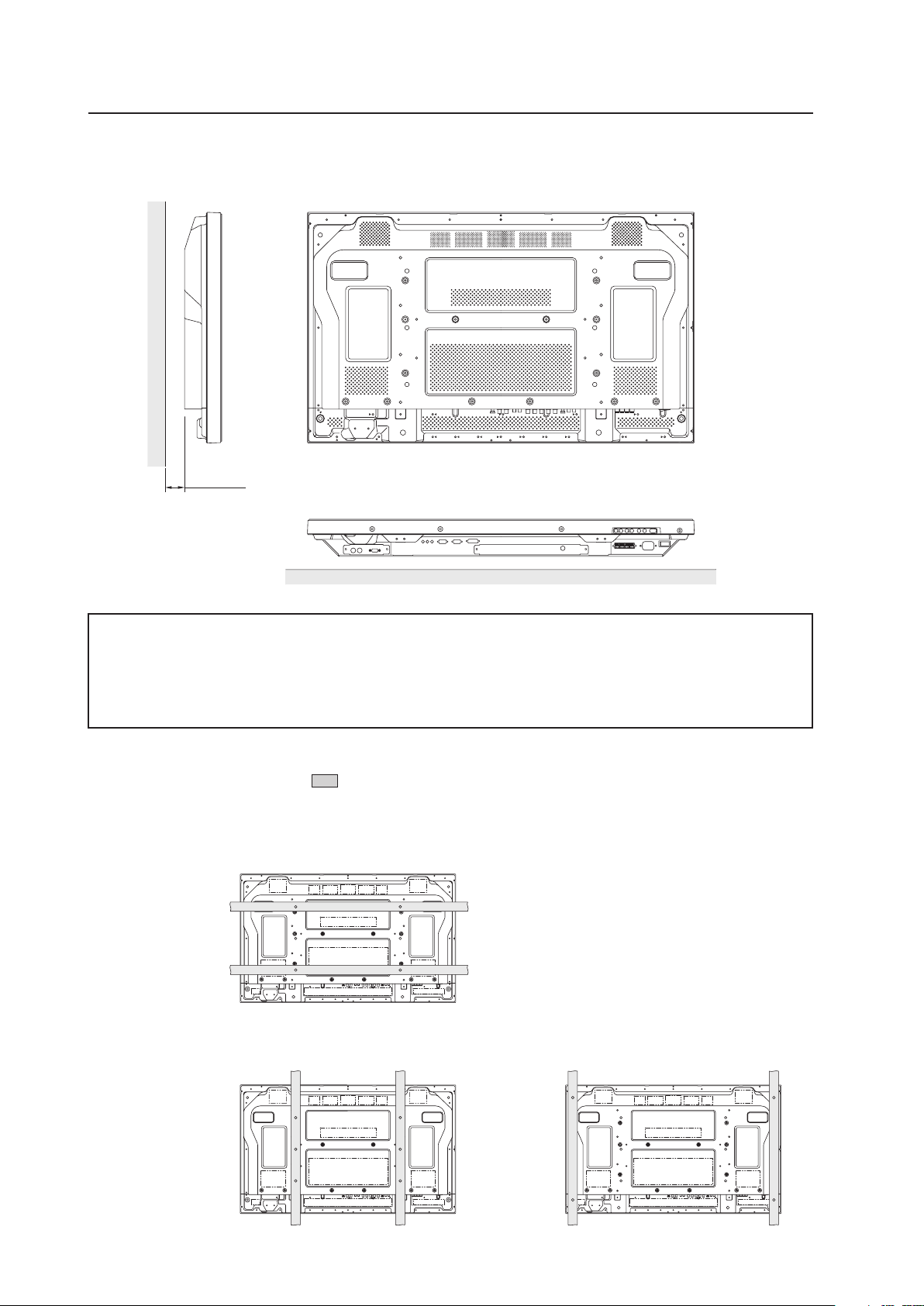
42
✩ Operating Temperature Restrictions
(*1)
• Ambient temperature: 0 °C to 35 °C
• The same operating temperature restrictions apply to the speaker system (PDP-S44-LR).
*1
For this installation, set the ‘FAN CONTROL’ to ‘MAX’ as shown in “5.4.3 Adjustment and Setting in the Integrator Mode 14)
Cooling Fan Control Setting” (pg. 172).
3.4.8 Installed facing upward
(1) When installed on top of a horizontal surface <an open space other than a horizontal surface>
50 mm or more
Methods of Securing: Basic methods of securing are shown below. Avoid blocking or covering areas aside from those
indicated by . The methods indicated by a large “X” must not be used.
Before attaching the unit to fittings, double-check that the thickness and height of the fittings
and the number of bolts is correct.
(Also refer to “3.4.1 Mounting to fittings” (pg. 26).)
Special Installation (Installed facing upward)
Horizontal surface
Horizontal surface
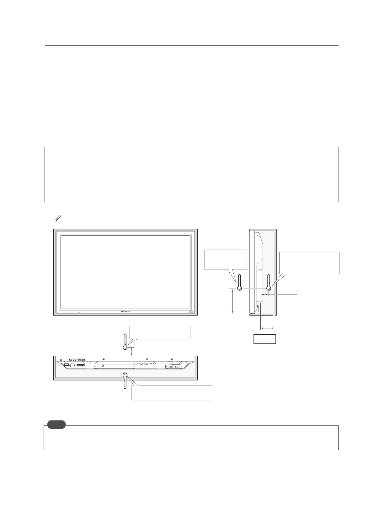
43
(2) When the Plasma Display is in a confined space
Operating this display in confined spaces is not recommended.
• If the display is to be used in confined spaces, observe the following conditions shown in the drawing below:
A ≥ 50
• If heat remains in the enclosed space, the temperature may rise causing a malfunction or fire. As a precaution, the
inner wall should have sufficient heat resistance or fire resistance.
• Leave a space at least 10 mm wide when installing glass etc. on the front of the Plasma Display.
✩ Usage temperature conditions
(*1)
• Ambient temperature: 0 °C to 35 °C (Outside air temperature)
• Space enclosed by the back surface of the Plasma Display: 0 °C to 35 °C (Use a fan etc. to discharge air to
maintain this temperature range.)
*1
For this installation, set the ‘FAN CONTROL’ to ‘MAX’ as shown in “5.4.3 Adjustment and Setting in the Integrator Mode 14)
Cooling Fan Control Setting” (pg. 172).
Special installation (Installed facing upward)
10 mm
150 mm
50 mm
A
Outside air temperature
measuring point
Outside air
temperature
measuring point
Enclosed space air temperature
measuring point
Enclosed space air
temperature measuring
point
A ≥ 50
When installing the Plasma Display facing upwards, do not place anything on top of it nor apply any load on it from
above.
: Thermometer (temperature measurement point)
Note
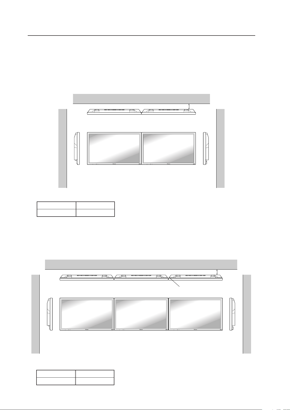
44
2 Installing three or more units (Horizontal connection)
The following table lists the operating temperature conditions. Use the units under conditions that keep the
outside atmosphere in this range.
A
Unit A Unit B
✩ Operating Temperature Restrictions
Distance from wall (A) Ambient temperature
50 mm or more 0 °C to 40 °C
Partition
Unit C
3.4.9 Horizontal connections
While the display is designed to accommodate side-by-side installations, keep in mind that specific installation
configurations may affect ventilation. Observe the following requirements:
1 Installation of up to two units (Horizontal connection)
The following table lists the operating temperature conditions when installing more than one panel. Use the units
under conditions that keep the outside atmosphere in this range.
Special installation (Horizontal connections)
A
Unit A Unit B
✩ Operating Temperature Restrictions
Distance from wall (A) Ambient temperature
50 mm or more 0 °C to 40 °C
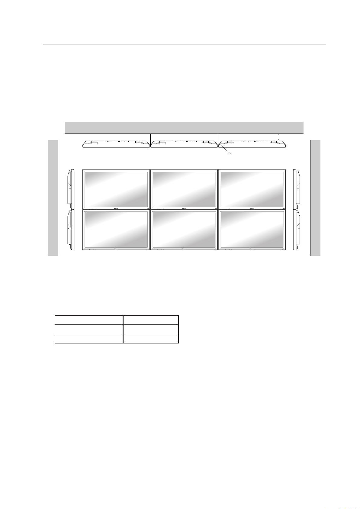
45
3.4.10 Multiple
While the display is designed to accommodate side-by-side installations, keep in mind that specific installation
configurations may affect ventilation. Observe the following requirements:
1 Installing multiple (2 Vertical units)
The following table lists the operating temperature conditions when installing more than one panel. Use the units
under conditions that keep the outside atmosphere in this range.
Special installation (Multiple)
A
Unit A Unit B Unit C
Partition
In case of lateral connections, ensure that left and right partitions are provided.
To prevent heat venting from one video wall plasma panel into another panel, each display must
be oriented in the same direction.
In the above example, each panel is shown with the Pioneer logo at the bottom.
✩ Operating Temperature Restrictions
Distance from wall (A) Ambient temperature
50 mm to 300 mm or less 0 °C to 35 °C
300 mm or more 0 °C to 40 °C

46
How to use the standard mounting components
4.1 Standard Mounting Components Features and Characteristics
In addition to reliability and vivid display resulting from its large screen area, brightness, and image quality, the Plasma
Display (PDP-425CMX/PDP-42MXE10) is thin and lightweight. This panel can be mounted in locations not possible for
conventional displays.
We considered various mounting patterns and operating conditions during the design of the Plasma Display (PDP-
425CMX/PDP-42MXE10). A wide range of standard mounting hardware is available for easy mounting.
¶ Video Card: PDA-5003/PDA-5004
The video card makes video input and analog RGB input possible.
This product has a total of three lines: a COMPOSITE (1), S INPUT (1), and an analog RGB INPUT or COMPONENT
INPUT (1). Furthermore, it can handle 3-line or 2-line audio, thus increasing the uses for video presentations.
¶ Table Top Stand: PDK-TS01
This on-board support designed for the Plasma Display enables vertical placement of the unit.
¶ Tilt Mount Unit: PDK-5011
This mount permits tilting of the display downward from the horizontal by up to 25 degrees. Mount depth is 143 mm
or less (in vertical position, without optional speaker). This hardware permits a wide range of viewing angles.
¶ Wall Mount Unit: PDK-WM01
Distance from the rear surface of the Plasma Display to the wall is 32 mm.
This mount provides installation holes for various wall-mounting arrangements. The mount is constructed so that it
can be easily attached to the main unit.
¶ Ceiling Mount Unit: PDK-5012
Simple rod-type mounting hardware permits display panning over a range of 45 degrees and up to 25-degree downward
tilting from the horizontal. This hardware enables installation of the unit in a wide variety of locations.
¶ Mobile Cart: PDK-5014
This is an extremely stable movable stand that one person can use to freely move the Plasma Display.
It can also be used to adjust the screen height and the screen angle to match the line of sight.
¶ Speaker System: PDP-S44-LR
2-way speakers feature 5 cm (2 in.) tweeter and 8 cm (3-3/16 in.) woofer in a vertical arrangement.

47
Handling the Standard Mounting Components
4.2 Handling the Standard Mounting Components
4.2.1 Handling precautions
This section of the manual discusses ways to mount, install, and handle the mounting hardware exclusively designed
for Pioneer Plasma Displays. Mounting should be performed by qualified experts.
Refer all installation and mounting work to qualified installers, or request assistance from a Pioneer dealer.
4.2.2 Precautions for installation contractors
1) Before installation
Observe the specifications supplied in “3.1 Installation Site Requirements” earlier in this manual.
2) During Installation
Carefully read and observe the contents of this section of the manual.
The installation work should be performed by two or more people.
3) After installation
After installation the mounting hardware, check for adequate strength and properly tightened screws. Repeat this
inspection after mounting the display.
4) Delivering to the customer
(1)Explaining mounting precautions
The mounting contractor is responsible for explaining the following precautions to the customer after mounting
and installation work is complete. Even if the particulars of an installation are letter-perfect, your work may be
perceived as inadequate unless you patiently and thoroughly explain these precautions to the customer.
¶ The following are highly dangerous and must be avoided at all times:
• Any sudden application of force, including pushing and pulling
• Splashing water on the unit
• Placing any object on the unit
• Touching mount screws and other mounting hardware
¶ For worry-free use of the unit:
• If problem arises, the user should immediately ask the installation contractor to inspect the unit and make
repairs if necessary.
• To guard against accidents, ask the customer avoid making tilt or height adjustments. Changes should be
referred to the installation contractor.
(2)Mounting contractor contact form
As the mounting and installation contractor, please complete the contractor contact form supplied with the unit
and give it to the end-user after post-installation inspections are complete.
(3)Periodic inspections
Over time, aging of various components of the suspension/mounting hardware that may not be readily visible can
render the installation unreliable. This may lead to the display breaking free of its mounting. Please recommend
periodic inspections.
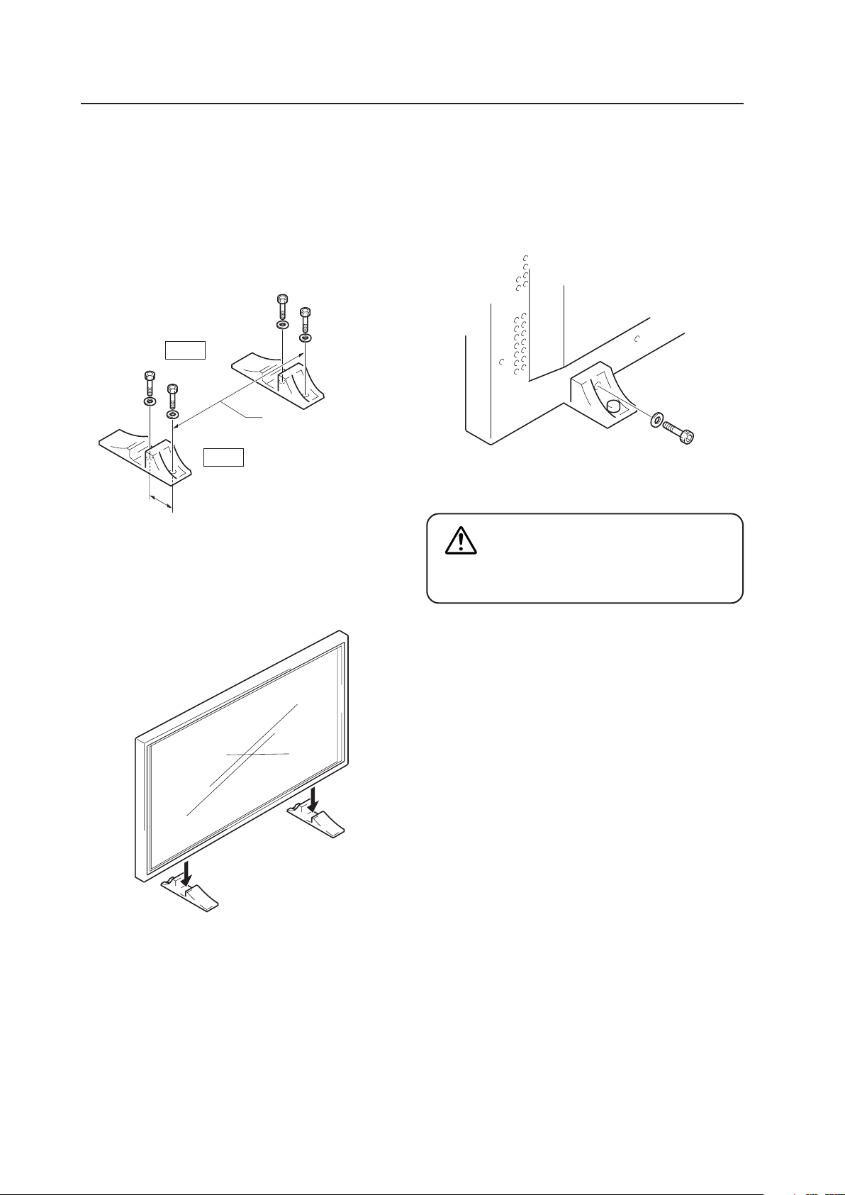
48
4.3 Installation of the Attachment Stand
Be sure to fix the supplied stands to the installation surface.
Use commercially available M8 bolts that are 25 mm
longer than the thickness of the installation surface.
Installation of the Attachment Stand
1.
Fix the supplied stands to the installation surface at
each of the 4 prepared holes using commercially
available M8 bolts.
2.
Insert the unit into the stand.
3.
Tighten the bolt against the washer so as to secure
the unit.
After manually tightening the bolts, completely
tighten them with the attached tools.
The unit weights 30 kg. or more.
Its thinness makes it unstable. Therefore,
it should be unpacked, carried, and
installed by two or more people.
CAUTION
Front
Rear
110 mm
Use a 6 mm hexagonal
wrench to tighten the bolt.
Always install the supplied display stands
according to the dimensions shown in
the accompanying illustration.
517 mm
(Bolt hole thread pitch)
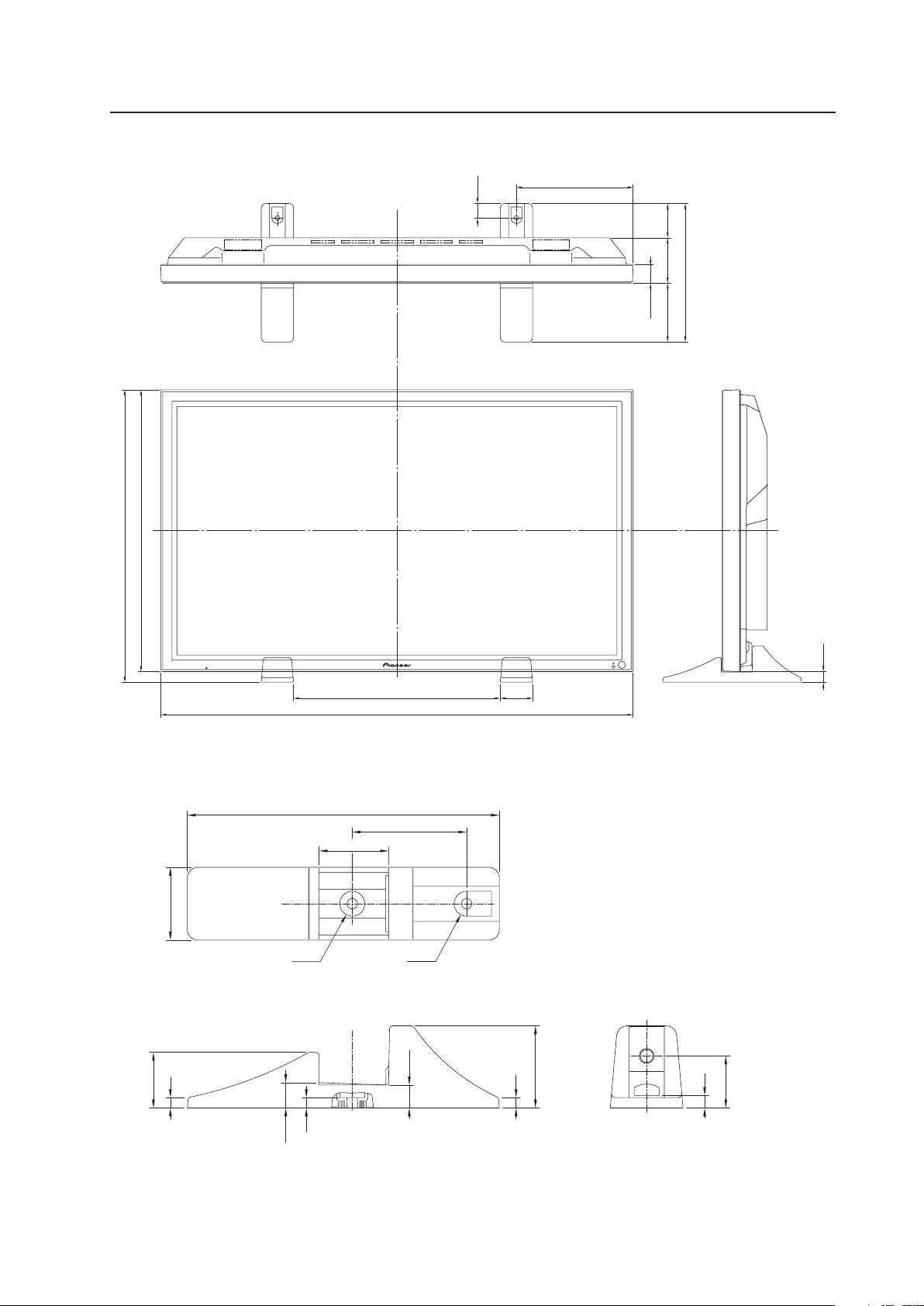
49
Installation of the Attachment Stand
Dimensions
(Unit: mm)
23
610
633
447.2 70
1022
40.4
74.398
127.7
300
252.4
31.4
22.1
10
79
10
53.5
24.3
10
12
50
110
66.8
ø
24
R12
70
300

50
4.4 Video Card: PDA-5003/PDA-5004
4.4.1 Specifications
External dimensions ................. PDA-5003: 301.5 mm (W) × 27.6 mm (H) × 148.9 mm (D)
(11-7/8 in. (W) × 1-1/8 in. (H) × 5-7/8 in. (D))
PDA-5004: 301.5 mm (W) × 27.6 mm (H) × 148.3 mm (D)
(11-7/8 in. (W) × 1-1/8 in. (H) × 5-27/32 in. (D))
Weight ....................................... 0.4 kg (14 oz)
Dimensions of packaging......... 359 mm (W) × 68 mm (H) × 234 mm (D)
(14-3/16 in. (W) × 2-11/16 in. (H) × 9-3/16 in. (D))
Package weight......................... 1.4 kg (3.1 lbs.)
Input/Output jacks
7 PDA-5003
Video-related
INPUT1 Input The following signal is supported only when a PDA-5003 is installed.
• Component video signal
Y ........................ 1 Vp-p/75 Ω/negative sync.
P
B
/C
B
, P
R
/C
R
........ 0.7 Vp-p (color 100 %)/75 Ω
INPUT2 Input DVI-D 24-pin connector
Digital video signal (HDCP supported)
INPUT3 Input S-VIDEO jack (Mini-DIN, 4-pin connector)
• Y/C separate video signal
Y ........................ 1 Vp-p/75 Ω/negative sync.
C ........................ 0.286 Vp-p/75 Ω (NTSC)
0.3 Vp-p/75 Ω (PAL)
INPUT4 Input BNC jack
• Composite video signal ........ 1 Vp-p/75 Ω/negative sync.
Output BNC jack .................................. 75 Ω/with buffer
INPUT5 Input BNC jack × 5
• RGB signal (for SYNC ON G)
RGB ........................... 0.7 Vp-p/75 Ω/no sync.
HD/VS, VD ................. TTL level/positive and negative polarity/75 Ω or 2.2 kΩ
(with impedance switching)
SYNC ON G ............... 1 Vp-p/75 Ω/negative sync.
• Component video signal
Y ................................ 1 Vp-p/75 Ω/negative sync.
P
B
/C
B
, P
R
/C
R
................ 0.7 Vp-p (color 100 %)/75 Ω
Audio-related
Input AUDIO INPUT (for INPUT3/4)
Pin jack (×2)
L/R ............ 500 mVrms/more than 10 kΩ
AUDIO INPUT (for INPUT5)
Pin jack (×2)
L/R ............ 500 mVrms/more than 10 kΩ
Video Card: PDA-5003/PDA-5004

51
7 PDA-5004
Video-related
INPUT1 Input The following signal is supported only when a PDA-5004 is installed.
• Component video signal
Y ........................ 1 Vp-p/75 Ω/negative sync.
P
B
/C
B
, P
R
/C
R
........ 0.7 Vp-p (color 100 %)/75 Ω
INPUT2 Input DVI-D 24-pin connector
Digital video signal (HDCP supported)
INPUT3 Input S-VIDEO jack (Mini-DIN, 4-pin connector)
• Y/C separate video signal
Y ........................ 1 Vp-p/75 Ω/negative sync.
C ........................ 0.286 Vp-p/75 Ω (NTSC)
0.3 Vp-p/75 Ω (PAL)
INPUT4 Input RCA jack
• Composite video signal ........ 1 Vp-p/75 Ω/negative sync.
Output RCA jack .................................. 75 Ω/with buffer
INPUT5 Input RCA jack
• SYNC ON G ....... 1 Vp-p/75 Ω/negative sync.
RGB ................... 0.7 Vp-p/75Ω/no sync.
• Component video signal
Y ........................ 1 Vp-p/75 Ω/negative sync.
P
B/CB, PR/CR ........ 0.7 Vp-p (color 100 %)/75 Ω
Audio-related
Input AUDIO INPUT (for INPUT3)
Pin jack (×2)
L/R ............ 500 mVrms/more than 10 kΩ
AUDIO INPUT (for INPUT4)
Pin jack (×2)
L/R ............ 500 mVrms/more than 10 kΩ
AUDIO INPUT (for INPUT5)
Pin jack (×2)
L/R ............ 500 mVrms/more than 10 kΩ
Accessories
Label for remote control unit............................... × 1
Connector indicator label..................................... × 1
Screw (3 × 8) ....................................................... × 2
Operating instructions ......................................... × 1
Warranty.............................................................. × 1
Video Card: PDA-5003/PDA-5004
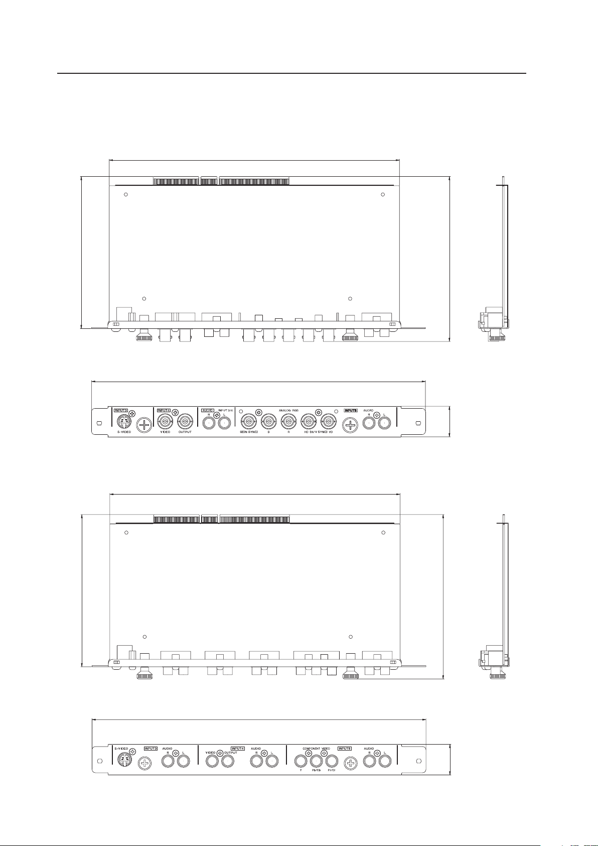
52
4.4.2 External Dimensions
(Unit: mm)
7 PDA-5003
Video Card: PDA-5003/PDA-5004
148.9
137.3
301.5
27.6
262
7 PDA-5004
137.3
148.3
27.6
301.5
262
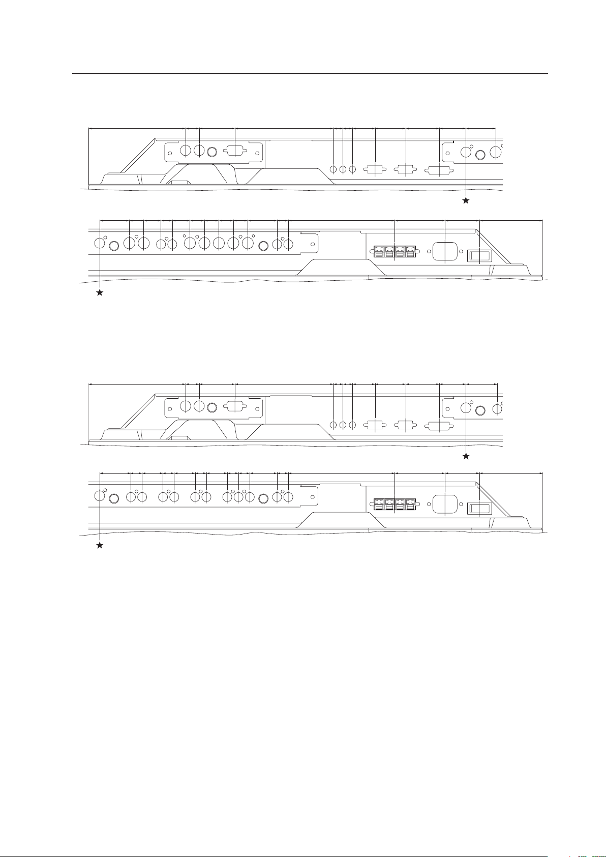
53
<PDP-425CMX/PDP-42MXE10 connection panel: when equipped with PDA-5003>
★: Symbol indicates the alignment point.
<PDP-425CMX/PDP-42MXE10 connection panel: when equipped with PDA-5004>
★: Symbol indicates the alignment point.
(121) 17 44.5 122.6 12 12 28 38 42 33 37
37 18 21.5 14 22 18 18 18 18 36.5 14 132.6 62.5 43
(78.8)
(121) 17 44.5 122.6 12 12 28 38 42
33 39
39 14 26 14 26 14 26 14 14 34 14 132.6 62.5 43 (78.8)
Video Card: PDA-5003/PDA-5004
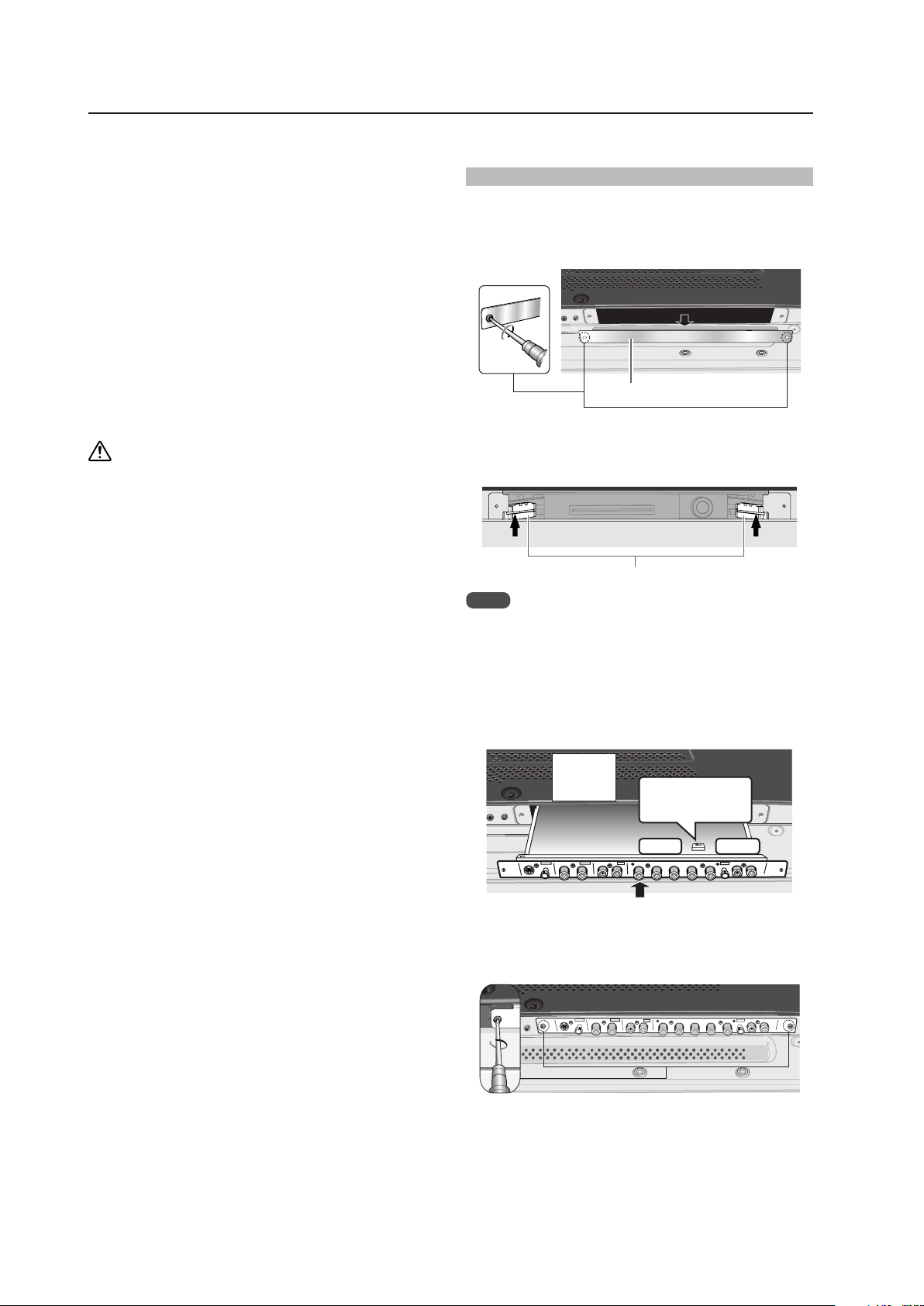
54
4.4.3 Installing procedures
Installation instructions are listed below. When installing
the unit, if a screw or other object should drop inside the
Plasma Display, immediately consult your nearest Pioneer
Service Center. Continuing operation may damage the
panel. This device has been designed for installation on the
Pioneer Plasma Display PDP-425CMX/PDP-42MXE10.
Installation procedures are as follows:
Check the following before installing this video card:
• Plasma Display is disconnected from the computer and
any other devices.
• The Plasma Display is unplugged from the wall outlet
before installing/removing a card from a panel slot.
Installation Notes:
• Do not install the PDA-5002 on the PDP-425CMX/PDP-
42MXE10 display units.
• When opening the protective cover, take care not to
drop screws or other objects in the opening. Objects
dropped inside the display may cause damage or
malfunction.
• When installing a video card, if the Plasma Display is
laid with its screen side facing down, the work surface
should be flat and level. The packing material, a blanket,
or other soft material should be spread on the work
surface to protect the screen before laying the panel
down. Take care to prevent scratches or other damage
to the unit from tools or other objects. Never rest the
display on a surface in such a way that weight or
pressure is placed only on the screen surface.
• This video card has been designed for exclusive use with
the Pioneer Plasma Display PDP-425CMX/PDP-
42MXE10. Do not attempt unauthorized modifications
or alterations since malfunction or damage may result.
• Take care not to modify or damage the card’s internal
devices in any way.
• Before installation, take precautions to eliminate static
electricity on your body. Do not touch the card’s circuitry
or devices.
• This device has not been designed to be repeatedly
removed and reinstalled. Avoid removing the card once
it is installed.
• When installing the PDA-5003, it may be necessary to
adjust the impedance selector switch setting. Confirm
this item before installing.
• Prior to insertion, use a cloth containing ethanol to clean
the PCI bus. Wipe in the direction of the electrodes to
remove dirt and dust. Wiping with a dry cloth may cause
damage due to static electricity.
Video Card: PDA-5003/PDA-5004
Installation
Illustration depicts PDA-5003 model
1 Remove the protective cover over the video card
slot on the Plasma Display’s terminal panel.
Protective cover
2 Align the video card with the two rails visible inside
of the port then gently and evenly insert the card.
rails
Notes
• Be very careful when inserting the card. Aim the card’s
mounting surface oriented toward the rear of the Plasma
Display. The card or display may be damaged if the card
is inserted crookedly or with excessive force.
• Impedance selector switch is found only on the PDA-
5003.
AUDIO
INPUT5
INPUT 3/4
AUDIO
VIDEO
ANALOG RGB
HD (H/V SYN C)
S-VIDEO I NPUT3
INPUT4
Impedance
selector switch
75 Ω 2.2 kΩ
Device
mounting
surface
3 After inserting the video card all the way into the
slot, confirm that it is seated securely. The screws
removed in step 1 to secure the card in place.
AUDIO
INPUT5
INPUT 3/4
AUDIO
VIDEO
ANALOG RGB
HD (H/V SYNC )
S-VIDEO INPUT3
INPUT4
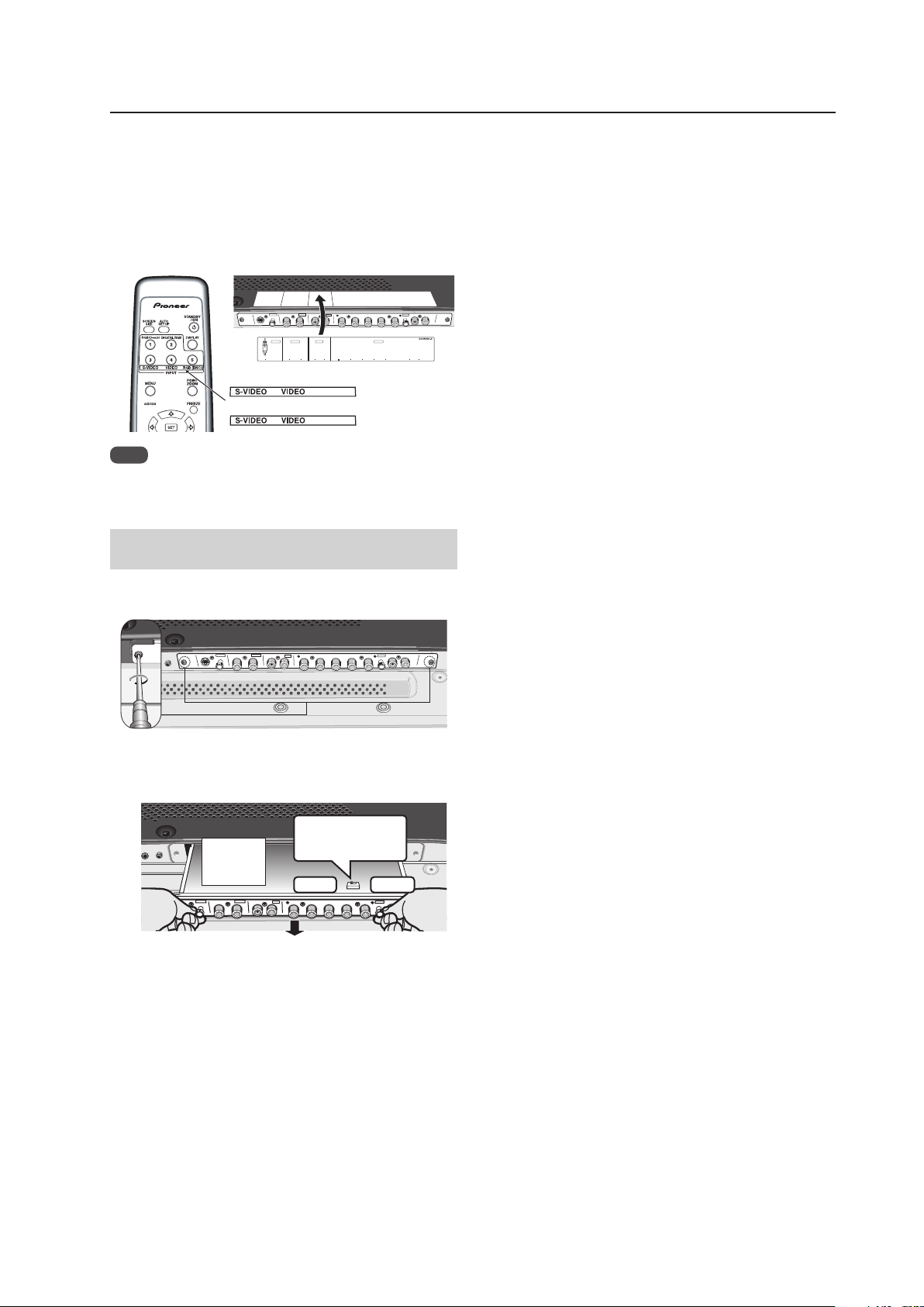
55
Video Card: PDA-5003/PDA-5004
4 Affix the accessory connector indicator label to the
Plasma Display then affix the remote control label
to the remote control that is furnished with the
Plasma Display.
Notes
Note
Use a soft cloth to gently wipe away any dust or soiling
from the surface before affixing the label.
Video Card Removal (Be careful not to insert
and remove it frequently).
1 Remove the two screws holding the video card.
AUDIO
INPUT5
INPUT 3/4
AUDIO
VIDEO
ANALOG RGB
HD (H/V SYNC )
S-VIDEO INPUT3
INPUT4
2 Holding the inside tabs, pull the video card straight
out.
AUDIO
INPUT5
INPUT 3/4
AUDIO
VIDEO
ANALOG RGB
HD (H/V SYN C)
S-VIDEO I NPUT3
INPUT4
Impedance
selector switch
75 Ω
2.2 kΩ
Device
mounting
surface
AUDIO
INPUT5
INPUT 3/4
AUDIO
VIDEO
ANALOG RGB
HD (H/V SYNC)
S-VIDEO INPUT3
INPUT4
INPU T3
S-VI DEO
VIDE O INPU T3
/
4 ANALOG RGB AUDIO
(ON SYNC) (H/V SYNC)
IN OU T R L R LG B R HD V D
INPU T4 INPUT5AUDIO
RGB (BNC)
COMPONENT
PDA-5003
PDA-5004
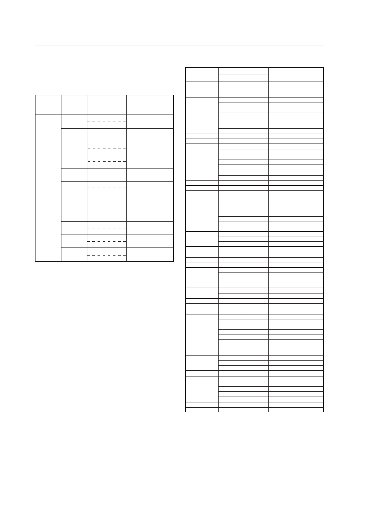
56
Video Card: PDA-5003/PDA-5004
Signal Format
50
Component
RGB
Component
RGB
Component
RGB
Component
RGB
Component
RGB
Component
RGB
Component
RGB
Component
RGB
Component
RGB
Component
RGB
Component
RGB
Horizontal
Frequency
Fh (kHz)
Remark
15.625
28.13
31.25
37.50
56.20
62.50
15.734
31.5
33.75
45.0
67.5
Vertical
Frequency
Fv (Hz)
60
625i(576i)/SDTV
1125i(1080i)/HDTV
625p(576p)/SDTV
750p(720p)/HDTV
1125p(1080p)/HDTV
520i(480i)/SDTV
525i(480i)/SDTV
525p(480p)/SDTV
1125i(1080i)/HDTV
1125i(1035i)/HDTV
750p(720p)/HDTV
1125p(1080p)/HDTV
INPUT Response Signals
INPUT 1, 5
7 Video signals supported ★ (applies only when
equipped with PDA-5003/PDA-5004)
7 PC signals supported
Resolution
(Dot x Line)
Vertical
Remark
Horizontal
70.1 Hz
70.1 Hz
85.1 Hz
60 Hz
66.7 Hz
72.8 Hz
75 Hz
85 Hz
100.4 Hz
120.4 Hz
60 Hz
60 Hz
56 Hz
60 Hz
72 Hz
75 Hz
85 Hz
99.8 Hz
120 Hz
74.6 Hz
60 Hz
60 Hz
60 Hz
70 Hz
75 Hz
(74.9 Hz)
85 Hz
100.6 Hz
56 Hz
60 Hz
70 Hz
60 Hz
59.9 Hz
60 Hz
60 Hz
60 Hz
72 Hz
75 Hz
75.1 Hz
66 Hz
76 Hz
60 Hz
60 Hz
60 Hz
60 Hz
71.2 Hz
72 Hz
75 Hz
76.1 Hz
85 Hz
100.1 Hz
60 Hz
75 Hz
85 Hz
60 Hz
60 Hz
65 Hz
70 Hz
75 Hz
85 Hz
60 Hz
60 Hz
640x400
720x400
640x480
848x480
852x480
800x600
832x624
1360x765
1024x768
1280x768
1360x768
1376x768
1280x800
1280x854
1152x864
1152x870
1152x900
1440x900
1280x960
1280x1024
1400x1050
1680x1050
1600x1200
1920x1200
1920x1200RB
Apple Macintosh 13”
I/O DATA
I/O DATA
I/O DATA
I/O DATA
I/O DATA
Apple Macintosh 16”
Work station (SGI)
( ) indicates Apple
Macintosh 19”
I/O DATA
I/O DATA
I/O DATA
CVT
PC
Apple Macintosh 21”
Sun Microsystems LO
Sun Microsystems HI
Apple Macintosh 17”
Work station (SGI)
Work station (EWS4800)
Work station (EWS4800)
Work station (HP)
Work station (SUN)
I/O DATA
CVT
CVT
31.5 kHz
31.5 kHz
37.9 kHz
31.5 kHz
35.0 kHz
37.9 kHz
37.5 kHz
43.3 kHz
51.1 kHz
61.3 kHz
31.0 kHz
31.7 kHz
35.2 kHz
37.9 kHz
48.1 kHz
46.9 kHz
53.7 kHz
63.0 kHz
75.7 kHz
49.7 kHz
47.7 kHz
48.4 kHz
49.7 kHz
56.5 kHz
60.0 kHz
(60.2 kHz)
68.7 kHz
80.5 kH
119.4 Hz
z
95.6 kHz
45.1 kHz
47.8 kHz
56.1 kHz
47.7 kHz
48.3 kHz
49.7 kHz
53.1 kHz
53.7 kHz
64.9 kHz
67.5 kHz
68.5 kHz
61.8 kHz
71.7 kHz
56.0 kHz
60.0 kHz
85 Hz 85.9 kHz
64.0 kHz
64.6 kHz
75.1 kHz
78.1 kHz
80.0 kHz
81.1 kHz
91.2 kHz
108.5 kHz
65.3 kHz
82.3 kHz
93.9 kHz
65.3 kHz
75.0 kHz
81.3 kHz
87.5 kHz
93.8 kHz
106.3 kHz
74.6 kHz
74.0 kHz
Refresh rate
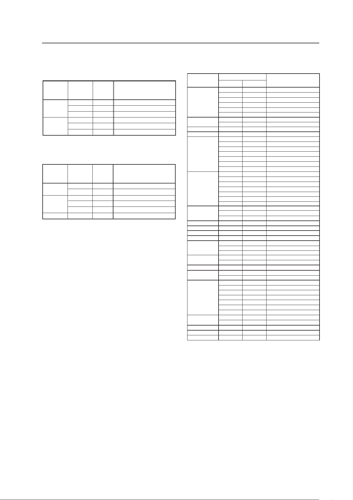
57
Video Card: PDA-5003/PDA-5004
INPUT 2
7 Video signals supported ★ (applies only when
equipped with PDA-5003/PDA-5004)
INPUT 3★
(applies only when equipped with PDA-5003/PDA-5004):
Y/C Separate video signal NTSC, PAL, SECAM, 4.43 NTSC, PAL
M, PAL N
INPUT 4★
(applies only when equipped with PDA-5003/PDA-5004):
Composite video signal NTSC, PAL, SECAM, 4.43 NTSC, PAL
M, PAL N
60 Hz
72.8 Hz
75 Hz
85 Hz
100.4 Hz
120.4 Hz
60 Hz
60 Hz
56 Hz
60 Hz
72 Hz
75 Hz
85 Hz
99.8 Hz
120 Hz
60 Hz
60 Hz
70 Hz
75 Hz
85 Hz
100.6 Hz
56 Hz
60 Hz
70 Hz
60 Hz
60 Hz
60 Hz
59.9 Hz
60 Hz
75 Hz
66 Hz
76 Hz
60 Hz
60 Hz
60 Hz
60 Hz
71.2 Hz
72 Hz
76.1 Hz
75 Hz
85 Hz
60 Hz
74.9 Hz
60 Hz
60 Hz
60 Hz
640x480
848x480
852x480
800x600
1024x768
1280x768
1280x800
1280x854
1360x768
1376x768
1152x864
1152x900
1440x900
1280x960
1280x1024
1400x1050
1680x1050
1600x1200
1920x1200RB
Work station (SGI)
I/O DATA
I/O DATA
Work station (SUN)
Work station (SUN)
Apple Macintosh17“
Work station (SGI)
Work station (EWS4800)
Work station (EWS4800)
Work station (HP)
Work station (SUN)
CVT
31.5 kHz
70.1 Hz720x480 31.5 kHz
85.1 Hz 37.9 kHz
37.9 kHz
37.5 kHz
43.3 kHz
51.1 kHz
61.3 kHz
31.0 kHz
31.7 kHz
35.2 kHz
37.9 kHz
48.1 kHz
46.9 kHz
53.7 kHz
63.0 kHz
75.7 kHz
48.4 kHz
49.7 kHz
56.5 kHz
60.0 kHz
68.7 kHz
119.4 Hz 95.6 kHz
80.5 kHz
45.1 kHz
47.8 kHz
56.1 kHz
49.7 kHz
53.1 kHz
47.7 kHz
48.3 kHz
53.7 kHz
67.5 kHz
72 Hz 64.9 kHz
61.8 kHz
71.7 kHz
56.0 kHz
85 Hz 85.9 kHz
60.0 kHz
64.0 kHz
64.6 kHz
75.1 kHz
78.1 kHz
81.1 kHz
80.0 kHz
91.2 kHz
65.3 kHz
82.3 kHz
65.3 kHz
75.0 kHz
74.0 kHz
Resolution
(Dot x Line)
Vertical
Remarks
Horizontal
Refresh rate
7 PC signals supported
Signal
Format
50
RGB
RGB
RGB
RGB
RGB
RGB
Horizontal
Frequency
Fh (kHz)
Remark
28.13
31.25
37.50
31.5
33.75
45.0
Vertical
Frequency
Fv (Hz)
60
1125i(1080i)/HDTV
625p(576p)x720 dot/SDTV
750p(720p)/HDTV
525p(480p)x720 dot/SDTV
1125i(1080i)/HDTV
750p(720p)/HDTV
Signal
Format
50
RGB
RGB
RGB
RGB
RGB
RGB
Horizontal
Frequency
Fh (kHz)
Remark
15.6
56.25
15.8
31.5
67.5
62.5
Vertical
Frequency
Fv (Hz)
60
625i(576i)/SDTV
1125p(1080p)/HDTV
525i(480i)/SDTV
525p(480p)x640 dot/SDTV
1125p(1080p)/HDTV
1250p/HDTV
The following signals are not formally supported, but can
be displayed (They are not recorded in EDID data).
50
* They may not be displayed normally depending on the
connected device.

58
4.5 Table Top Stand: PDK-TS01
4.5.1 Specifications
External dimensions ................. 566 mm (W) × 508 mm (H) × 339 mm (D)
(22-9/32 in. (W) × 20 in. (H) × 13-11/32 in. (D))
Weight ....................................... 4.0 kg (8.82 lbs.) (mounting hardware only)
34.5 kg (76 lbs.) (mounting hardware and Plasma Display)
Materials .................................... Base: plastic (ABS); Stand pipes: general structural steel tubes (STKMR-D)
Finish.......................................... Finish: Base: paint (Pioneer original color); Stand pipes: semi-matt black paint
Package dimensions ................. 640 mm (W) × 214 mm (H) × 415 mm (D)
(25-3/16 in. (W) × 8-7/16 in. (H) × 16-11/32 in. (D))
Package weight......................... 6.3 kg (13.9 lbs.)
Accessories
Base cover .......................................................... × 1
Stand pipes (left and right interchangeable) ........ × 2
Screw (4 × 8) ....................................................... × 4
Installation bolt 1 (M8 × 20) ............................... × 2
Installation bolt 2 (M8 × 40) ............................... × 2
Hexagonal wrench .............................................. × 1
Stabilization bolts ............................................... × 2
Operating instructions ......................................... × 1
Table Top Stand: PDK-TS01
✩ Operating Temperature Restrictions
• Ambient Temperature: 0 °C to 40 °C
✩ Operating temperature restrictions for when the speaker system (PDP-S44-LR) is attached.
• Ambient temperature: 0 °C to 40 °C
✩ Other factors
• Maintain sufficient clearance between the display and the wall (at least 100 mm)
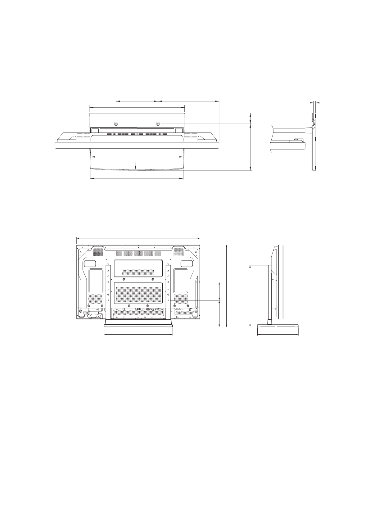
59
4.5.2 Installation coordinates for screws used to attach the stand to a surface
* When stabilizing the stand to a surface, use M6 longer than 20 mm.
(Unit: mm)
Table Top Stand: PDK-TS01
4.5.3 External Dimensions
7 When using Plasma Display
(Unit: mm)
675
150220
339
508
566
1022
64275
248
388
566
11.5
R6400
R4200
R6400
550
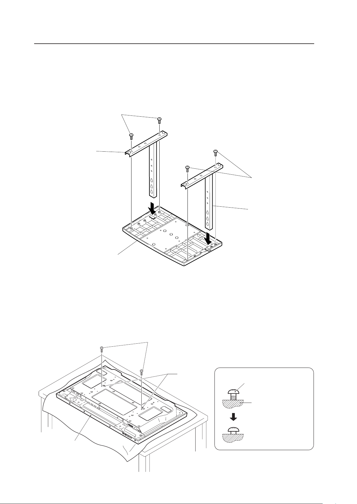
60
Table Top Stand: PDK-TS01
4.5.4 Stand assembling
1) Assembling Steps
1 Turn the base cover over so that the bottom is facing up.
2 Insert the stand pipes into the base cover.
3 Use the included screws to stabilize the stand pipes.
Base cover
Screws (4 × 8)
Stand pipe
Screws (4 × 8)
Stand pipe
Installation bolt 1
Plasma Display
Stop screwing down the
bolt when the threads are
no longer visible.
Holes "a"
Plasma Display housing
4.5.5 Attaching the Stand to the Plasma Display
1) Normal Installation
1 With the Plasma Display lying flat, insert and secure the two Installation bolts 1 (M8 × 20) in the holes "a" located in
the Plasma Display housing.
Tighten these bolts 1 until the threads are no longer visible when viewed from t he side (you will be unable to attach
the display if the bolts are screwed in completely).
Installation bolt 1 (M8 × 20)
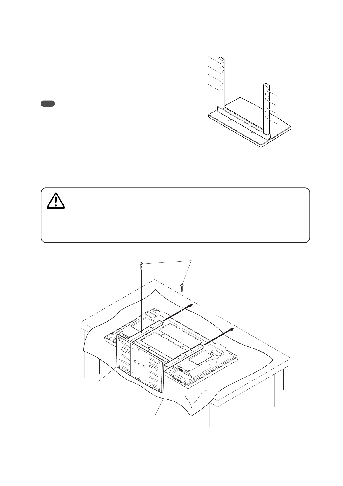
61
Table Top Stand: PDK-TS01
2 Hook the stand pipe holes A onto the screw heads of the installation bolts 1. Slide the stand up the main Plasma
Display until it engages the installation bolts 1. Once joined, the stand stops sliding at 19 mm.
3 Pass the installation bolts 2 (M8 × 40) through the stand pipes are A–A').
4 Tighten the installation bolts 1 securely with the provided hexagonal wrench.
1. Place a sheet or protective cover to protect the display from scratches or damage.
2. Assemble only with the Plasma Display lying flat on a table or similar surface.
3. Do not apply excessive pressure when tightening the bolts.
4. Move the stand so that the screw holes on the stand line up with nuts on the display panel.
5. The display weighs approximately 30 kg (66 lbs.) or more and has little depth, making the display
very unstable. For this reason at least two people are necessary for its setup and installation.
Installation bolts 2 (M8 × 40)
Table top stand
Sheet
A
A
´
B
´
B
B
A
A
´
B
´
Cautions
Regarding the stand pipe screw holes when the stand is
used as a desktop stand
Stand pipe screw holes when the stand is used as a desktop
stand:
• Specifications.............................................. Normal use
• Screw holes used with stand orientation ... A, A'
Note
Screw holes B and B' are for attaching options (available sepa-
rately).
Slide the stand
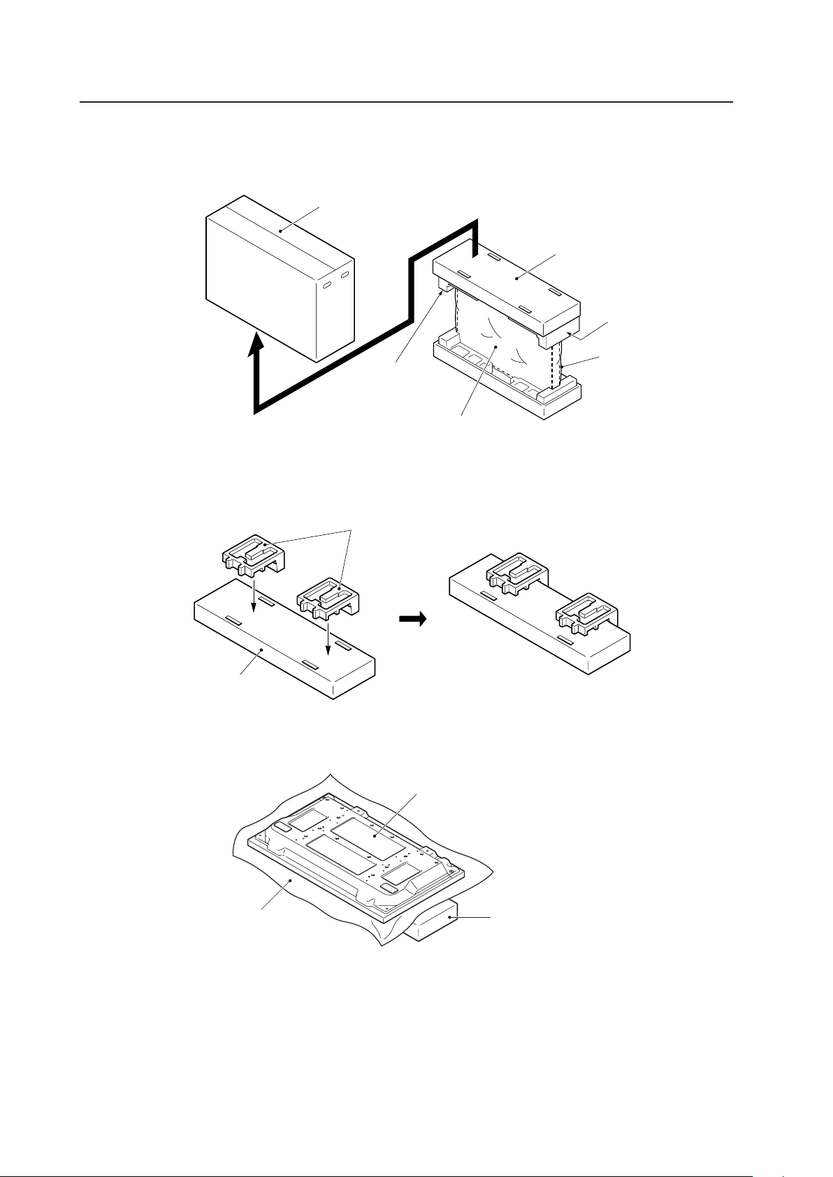
62
Table Top Stand: PDK-TS01
2) Instructions for using the main display packing material as a stand while working on the panel
Main Plasma Display packaging setup
Outer box
Inner box frame
Pad
Plasma Display
Mirror mat
Pads
Inner box frame
Plasma Display
Mirror mat
Inner box frame topped by two pads
Pad
1 Construct the stand for the Plasma Display using the inner box frame and pads shown in the figure above.
2 Set the Plasma Display down on the pads as shown in the figure below.
3 Follow the instructions in Steps 1-4 in "Normal Installation" to attach the stand to the Plasma Display.
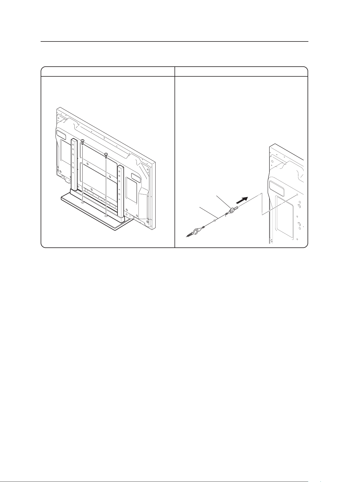
63
Table Top Stand: PDK-TS01
After assembling, connect the stand to the floor to prevent it from falling over.
1. Attach the stabilization bolts that come with the stand
to the Plasma Display.
2. Stabilize the display by attaching it to a wall or a
standing beam with a strong cord.
(Repeat the same steps laterally to stabilize the
assembly to the left and right.)
Use cord and hooks that are available on the market
(sold separately).
7 How to use the stabilization bolts
7 Stabilizing to the floor
÷ Use screws (sold separately) to attach and stabilize
the stand.
1
2

64
Tilt Mount Unit: PDK-5011
4.6 Tilt Mount Unit: PDK-5011
4.6.1 Specifications
External dimensions ................. 1022 mm (W) × 610 mm (H) × 143 mm (D) (40-1/4 in. (W) × 24-1/32 in. (H) × 5-5/8 in. (D))
(mounting hardware and Plasma Display)
Weight ....................................... 13.8 kg (30.4 lbs.) (mounting hardware only)
44.3 kg (97.7 lbs.) (mounting hardware and Plasma Display)
Materials .................................... General structural steel tubes (STKM-R), SS400, SPHC
Finish.......................................... Semi-matte black paint on rear (Original Pioneer color)
Dimensions of packaging......... 890 (W) × 120 (H) × 700 (D) mm
(35-1/8 (W) × 4-23/32 (H) × 27-9/16 (D) in.)
Package weight......................... 18.0 kg
(39.7 lbs.)
Layers of packing ...................... 20 layers
Components
Tilt mount unit ..................................................... × 1
Bolt M8 ............................................................... × 6
Hexagonal wrench .............................................. × 1
For wall-mounting, allow adequate space (a clearance of 300 mm or more) above and below the panel, as well as on the
right and the left.
✩ Operating Temperature Restrictions
• Ambient temperature: 0 °C to 40 °C
✩ Operating Temperature Restrictions for Upside-Down Installations
* Upside-Down Installation is unavailable with the PDK-5011.
✩ Operating temperature restrictions for when the speaker system (PDP-S44-LR) is attached.
• Ambient temperature: 0 °C to 40 °C
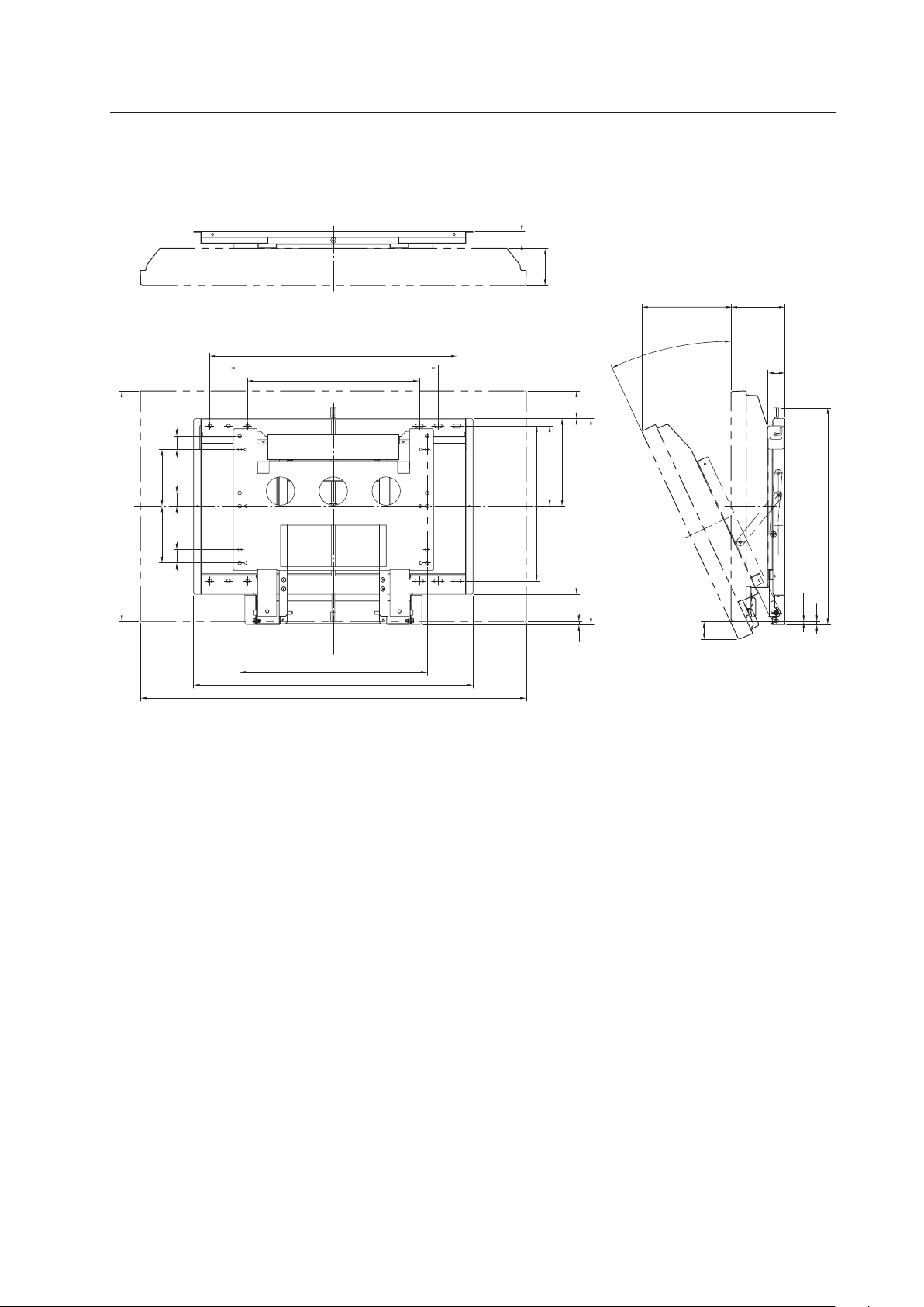
65
Tilt Mount Unit: PDK-5011
4.6.2 External Dimensions
7 When using Plasma Display
(Units: mm)
(236)
47
8
0.05
32
98
455
555
655
496
1022
212
410
232
465
545
8
73
150150
35
35 35
610
25°
740
573
45
(143)
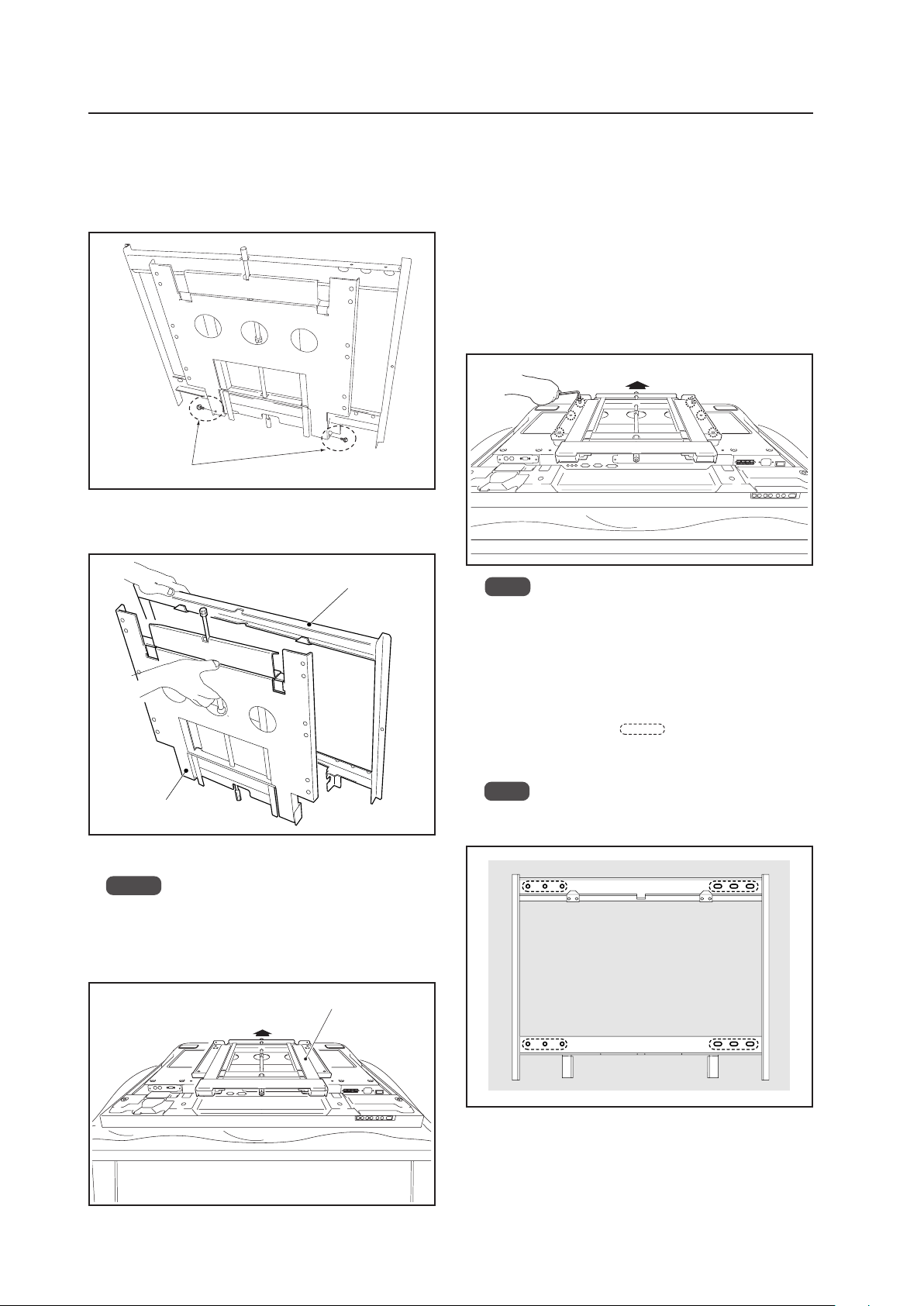
66
5 Attach the wall side hardware to the wall.
Install the wall side hardware (4 locations) symmetri-
cally on the left and right side (one at each location
from the center of the
). Wall strength and ma-
terial determines the type of screws and bolts (sold
separately) needed for this installation.
Note
Check the strength of the wall and beams before in-
stalling the display.
Tilt Mount Unit: PDK-5011
4.6.3 Assembling the mounting hardware and mounting the Plasma Display
Special screws (M6)
2 Remove the hardware on the wall side half and the
hardware on the PDP side half.
3 Attach the PDP side hardware to the Plasma Display.
Notes
• Place a sheet or protective cover to protect the
display from scratches or damage.
• Be sure to attach it on top of a flat table or similar
surface.
4 Fix the Plasma Display to the PDP side hardware with
M8 bolts (6 locations).
Use the holes marked with the red triangle "%".
If the 42-inch model is installed with an inclination of
18° or more, the top part of the screw used to adjust
the angle may be visible from a horizontal position in
front of the screen. In this case, you can hide the top
of the screw by using the holes without a red triangle
mark "%".
Wall side hardware
PDP side hardware
PDP side hardware
Top side of Plasma Display
1 Remove the special screws (2 locations) from the bot-
tom of the wall mounting unit.
Top side of Plasma Display
Note
Be sure to install speakers at this stage.
For the installation method, refer to the speaker
instruction manual.
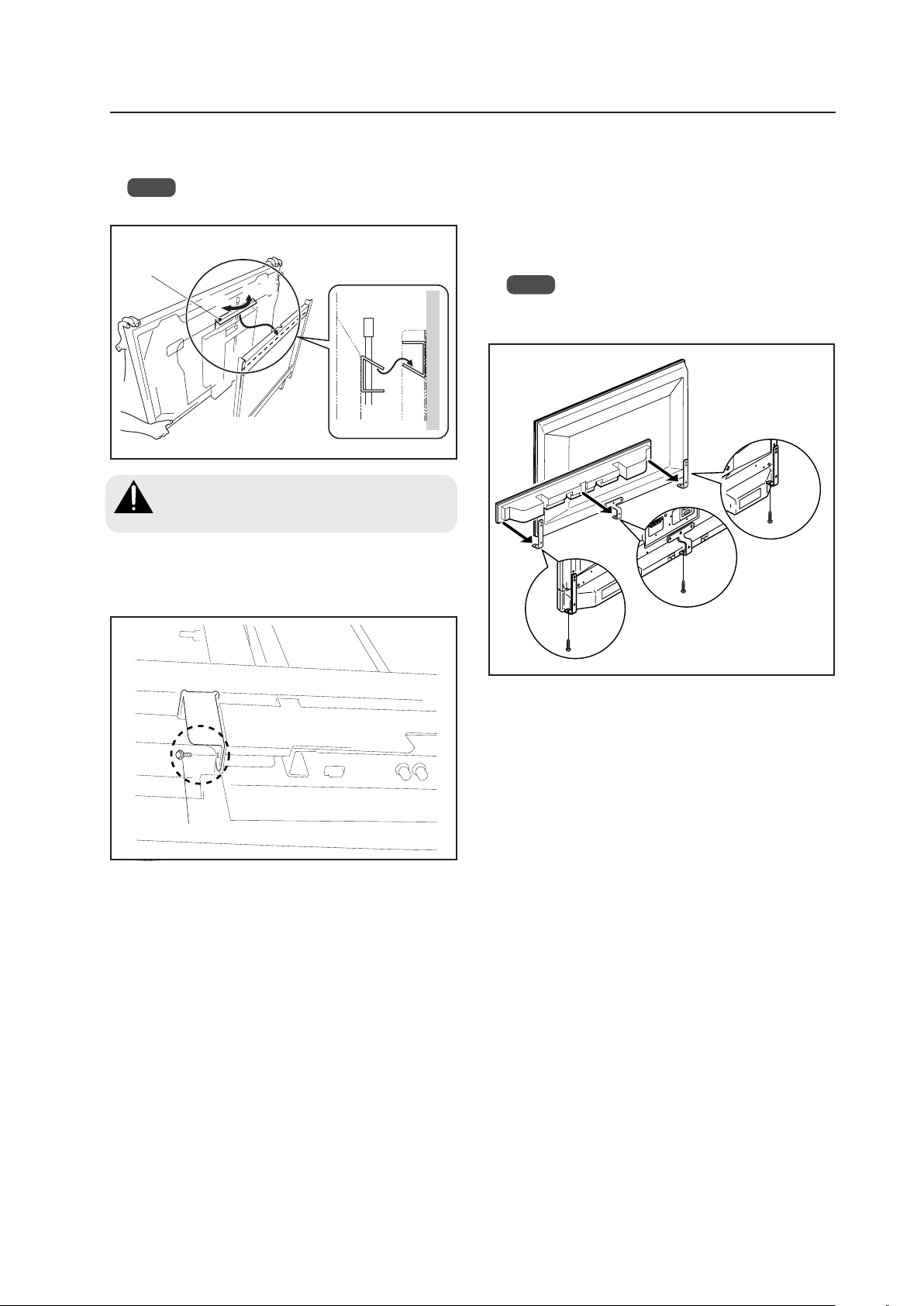
67
Tilt Mount Unit: PDK-5011
Hook
Closing
Opening
6 Attach the hook on the PDP side hardware to the wall
side hardware.
Note
Do not hold the speakers during the installation work.
Always have at least 2 people do this task.
Verify that the hook has been hung before
lifting the Plasma Display into place.
Caution
8 Install the under speaker (PDP-S39).
1 Connect the speaker cord to the terminal on the
speaker.
2 Place the speaker installation hardware on the
speaker. Using the screws that come with the
speaker, anchor both from the bottom (2 locations
on the left and right).
Note
Be sure to install the speaker with the hardware
attached vertically.
7 Fix the bottom of the hardware with the special screws
removed at step 1 (one on the left and one on the
right).
Special screw (M6)
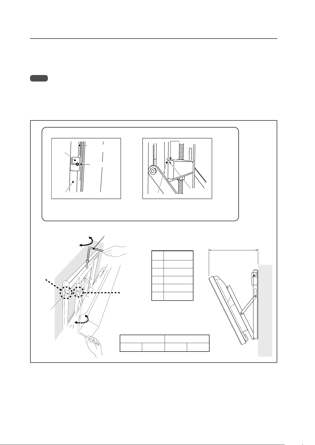
68
Tilt Mount Unit: PDK-5011
Opening
Closing
Hexagon wrench
Measuring the opening distance X provides
an approximate angle value.
X
When it is in this state, do not turn
the adjustment screw any further in
the closing direction.
B Criterion when its angle is 25°
When it is in this state, do not turn the
adjustment screw any further in the
opening direction.
Resin plate
A Criterion for the vertical location
Gap
disappears
Notch
End face of the plate
Matched in both
directions
Wall side hardware
Resin plate
Back of the
Plasma Display
A
B
4.6.4 Angle setup
This installation hardware allows the display to be tilted down freely at any angle from the vertical to 25°.
This adjustment must always be done by 2 people.
Adjust the angle by rotating the screws at the center top and center bottom of the wall side hardware (left or right).
Notes
• It is difficult turn the center-bottom screw while increasing the angle. When this happens, adjust the angle by turning
the top-center screw.
• Turn the screws very carefully to avoid damaging the wall.
• When a screw becomes tight at either end of the adjustment range, do not turn the adjustment screw any. Doing so
applies excessive force, deforming the screw.
Tilt Angle Criteria
Angle X
5° 194 (7-5/8)
10° 243 (9-1/2)
15° 290 (11-3/8)
20° 336 (13-1/4)
25° 379 (14-7/8)
Unit: mm (inch)
Angle of incline and appearance of the screw for angle
adjustment from a horizontal position on the front
Standard hole Upper hole
16° or more visible 23° or more visible
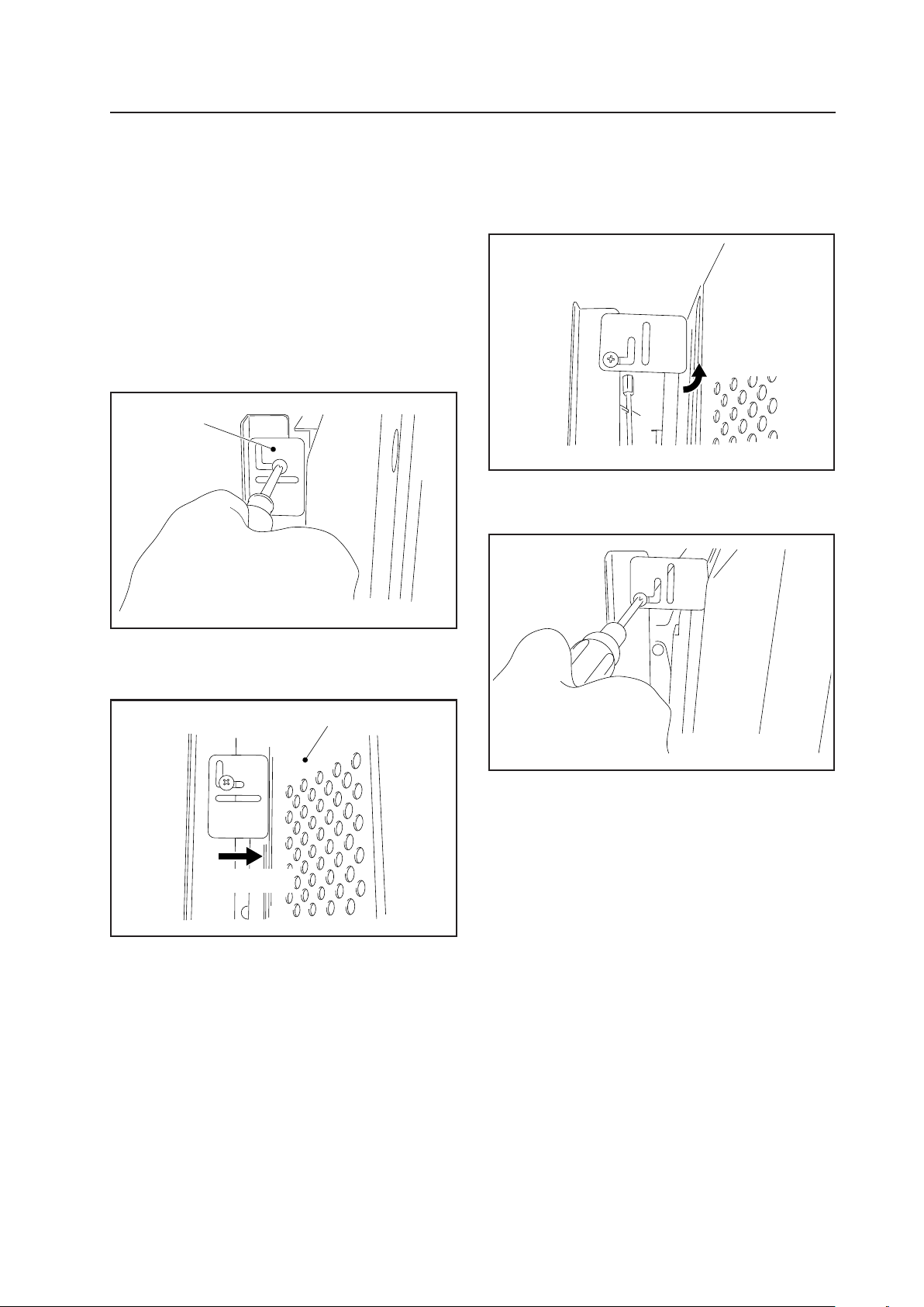
69
Tilt Mount Unit: PDK-5011
4.6.5 Measure to prevent shakiness when the unit is installed at a slight tilt
With this installation hardware, for structural reasons, the
top of the panel may be shaky when installed at a 5° angle
from the vertical position.
If this shakiness is a problem, reduce it by following the
instructions provided below.
1 Use a Philips driver (+) to loosen (left, right) the
installation screws on the resin plate used as a guideline
when installing it vertically (left, right). Allow the resin
plate to move freely.
2 Slide the resin plate (left, right) forward along the slit
to the rear cover of the Plasma Display.
3 If, when it is moved only forward, the distance is too
short, rotate the resin plate to use the longer side.
4 After setting the resin plate (left, right) in position,
retighten the screws that were loosened at step (1).
Resin plate
Rear cover of the Plasma Display
Slide forward
Rotated
You can use above method to reduce the shakiness that
occurs when the panel is installed at a slight angle.

70
4.7 Wall Mount Unit: PDK-WM01
4.7.1 Specifications
External dimensions ...............1022 mm (W) × 610 mm (H) × 130 mm (D) (40-1/4 in. (W) × 24-1/32 in. (H) × 5-1/8 in. (D))
(mounting hardware and Plasma Display)
Weight .....................................9.3 kg (20.5 lbs.) (mounting hardware only)
39.8 kg (87.7 lbs.) (mounting hardware and Plasma Display)
Materials ..................................SPHC, SS400
Finish........................................Semi-matte black paint on rear (Original Pioneer color)
Dimensions of packaging.......1070 mm (W) × 100 mm (H) × 500 mm (D)
(42-1/4 (W) × 3-15/16 (H) × 19-11/16 (D) in.)
Package weight.......................11.5 kg
(25.4 lbs.)
Layers of packing ....................30 layers
Components
Wall mount unit ................................................... × 1
Tilt adjustment metal fitting ................................ × 1
Bolt M8 ............................................................... × 6
Hexagonal wrench
(Opposite side 6 mm for M8 use) ....................... × 1
Stencil ................................................................. × 1
In wall-mounting installation allow adequate space (a clearance of 300 mm or more) above and below the panel, as well
as on the right and the left.
✩ Operating Temperature Restrictions
• Ambient temperature: 0 °C to 40 °C
✩ Operating Temperature Restrictions for Upside-Down Installations
* Upside-Down Installation is unavailable with the PDK-WM01.
✩ Operating temperature restrictions for when the speaker system (PDP-S44-LR) is attached.
• Ambient temperature: 0 °C to 40 °C
✩ Attachment Restrictions
• Install it on perpendicular walls, columns, etc.
It cannot be installed on an inclined surface.
Wall Mount Unit: PDK-WM01
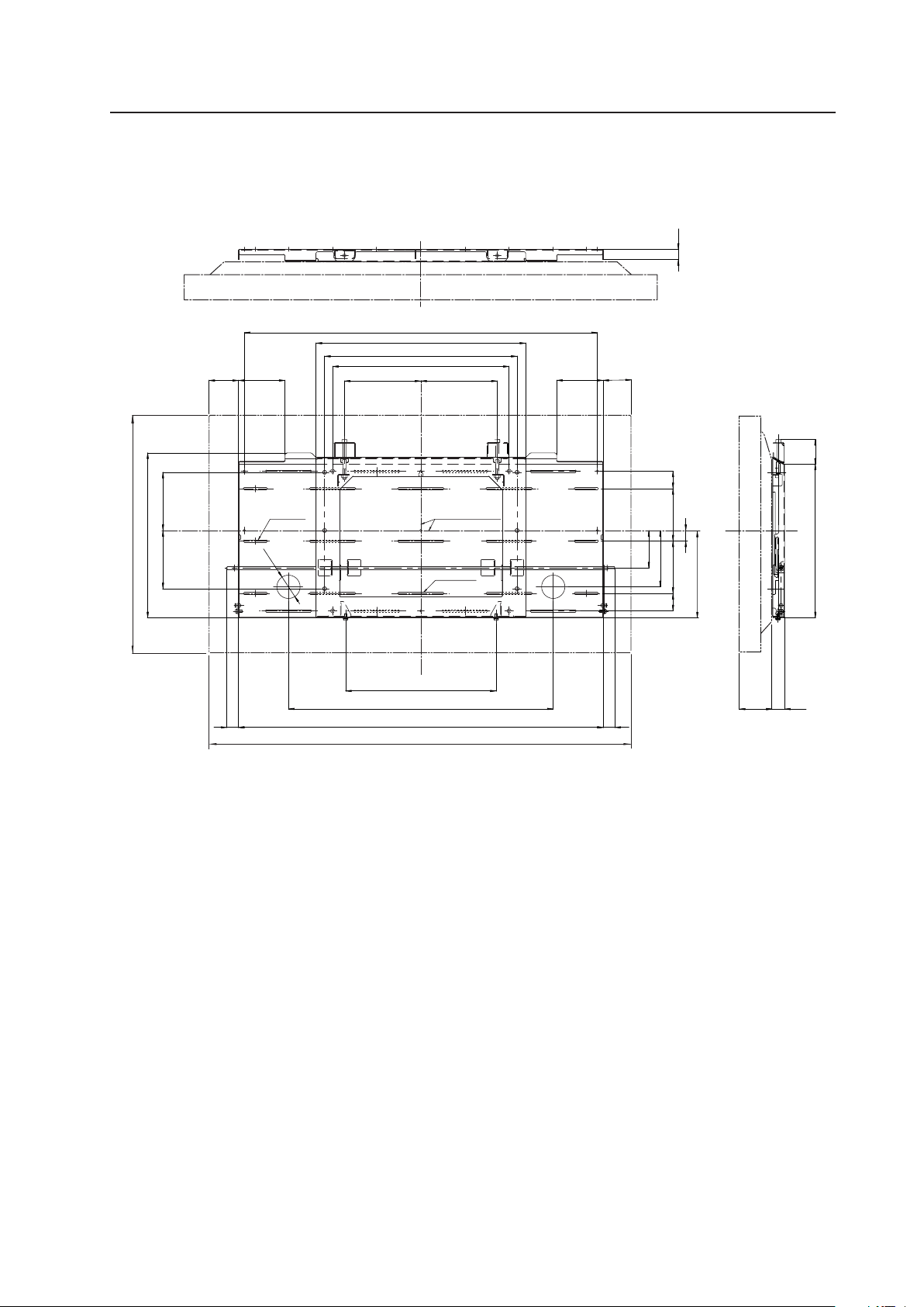
71
Wall Mount Unit: PDK-WM01
6-6 x 63
17-6 x 120
2-φ60
64
97
388
30
30
396
32
27
197197
98
455
540
910
145
27
135 135 4545
682.5
940
120
150150
(425)
120
496
225
41
41
Center line
(Center of the display)
1022
610
4.7.2 External Dimensions
7 When using Plasma Display
(Unit: mm)
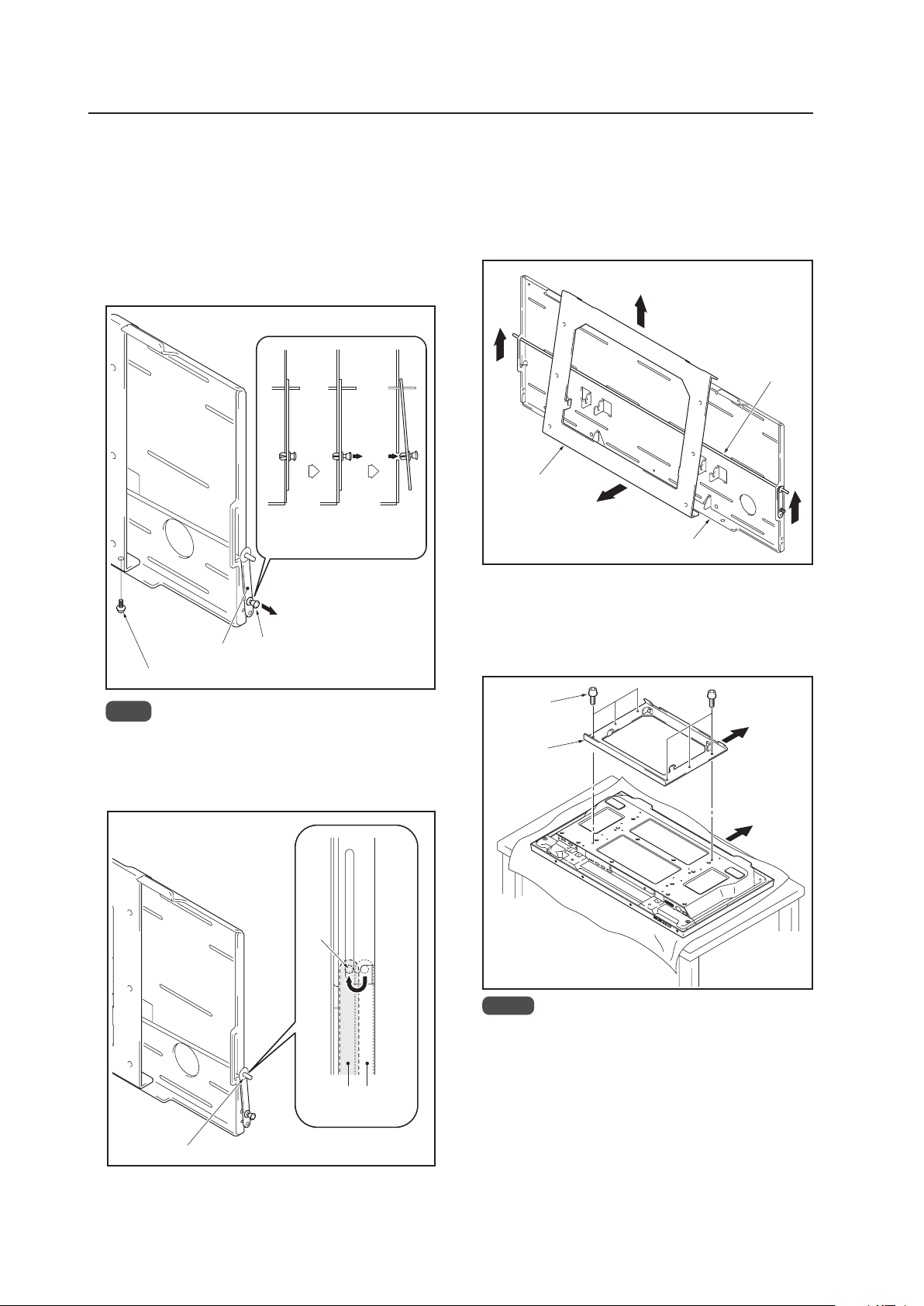
72
Wall Mount Unit: PDK-WM01
4.7.3 Assembling the mounting hardware and
mounting the display
1 Remove the push rivet of the lock plate and the bottom
anchor screw (M6 x 14 mm (9/16 inch)) (1 location: left
and right sides)
1 Move the push rivet of the lock plate to its
unlocked position (shown in the figure below).
2 Remove the anchor screw from the bottom.
Lock plate
Push rivet
Anchor screw (M6 x 14mm)
Unlocked
position
Locked
position
Pull the
push
rivet
2 Release the lock bar (1 location: left and right sides)
Lock bar
Set the lock bar in the
unlocked position.
Unlocked
position
Locked
position
Lock
bar
Note
Be careful not to lose the two anchor screws (M6
x 14 mm (9/16 inch)) because they will be used
later.
3 Remove the PDP side metal fitting
1 Lift the lock bar to the position where the lock on
the PDP side metal fitting is released.
2 While holding the lock bar up, pull out the bottom
of the PDP side metal fitting.
3 Lift then remove the PDP side metal fitting.
1
1
3
2
Lock bar
PDP side metal fitting
PDP side
metal fitting
Bolts M8
Top side of the
Plasma Display
4 Attach the PDP side metal fitting to the Plasma Display
1 Spread a sheet or similar material so that the
display will not be scratched or damaged.
2 Fix the PDP side metal fitting firmly to the Plasma
Display with M8 bolts (6 locations).
Notes
Always install it on top of a stable table or similar
surface.
If you plan to install speakers and cables, please
install them at this stage.
Do not connect cables for any other device.
For the speaker installation method, refer to the
speaker installation procedure in the Plasma
Display operating instructions.
Wall side metal fitting
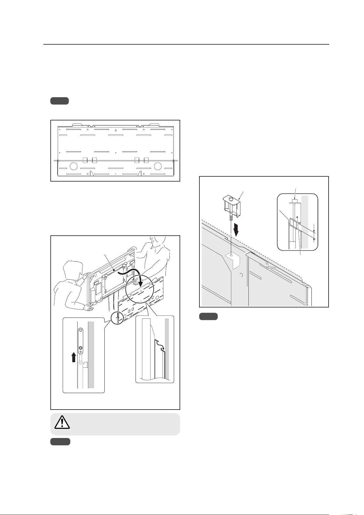
73
Wall Mount Unit: PDK-WM01
6 Hang the hook of the PDP side metal fitting on the
wall side metal fitting
1 Hang the hook on the ceiling surface part of the
PDP side metal fitting on the wall side metal
fitting.
2 Raise the lock bar to attach the Plasma Display.
Make sure that the lock bar is fully lowered.
Hook of the PDP side
metal fitting
Lift the lock bar to its
unlocked position.
Hang the hook.
1
2
Always have at least 2 people do this task.
Check that the hook has been hung before
lifting the Plasma Display.
Caution
7 Fine adjustment of the left-right tilt of the Plasma
Display.
If the Plasma Display is slightly tilted to the left or right
after it is installed on the wall, adjust this tilt by attaching
the adjustment metal fitting (at lone location on the
right and on the left).
Insert the tilt adjustment metal fitting in the notch on
the top surface of the PDP side metal fitting that is
tilted downward. Attach it by rotating the screw.
1 Rotate the screw until the gap between the wall
side metal fitting and the tilt adjustment metal
fitting disappears. When the gap between the
wall side metal fitting and the tilt adjustment
metal fitting has disappeared, the screw becomes
difficult to rotate and begins to lift up the Plasma
Display.
2 Rotate the screw to adjust the tilt.
Gap
Screw head
Tilt adjustment
metal fitting
Tilt adjustment
metal fitting
5 Install the wall side metal fitting to the wall
Fix it firmly in place symmetrically to the left and right
(4 or more locations).
Wall strength and material determines the type of
screws and bolts (sold separately) needed for this
installation.
Note
Chack the strength of the wall, columns, etc. before
beginning the installation.
Notes
If speakers are attached, do not hold the
speakers to perform this attachment.
Be careful that the wiring etc. is not caught in the
metal fitting or on the Plasma Display. When a
speaker is attached, the wiring is easily caught
between the wall and the speaker.
Note
The range that the tilt can be adjusted by the screw
is about 5 mm (3/16 inch). The screw rotates about
3 times. Be careful not to over-rotate the screw.
If the screw is turned too much, the metal fitting
may be damaged.
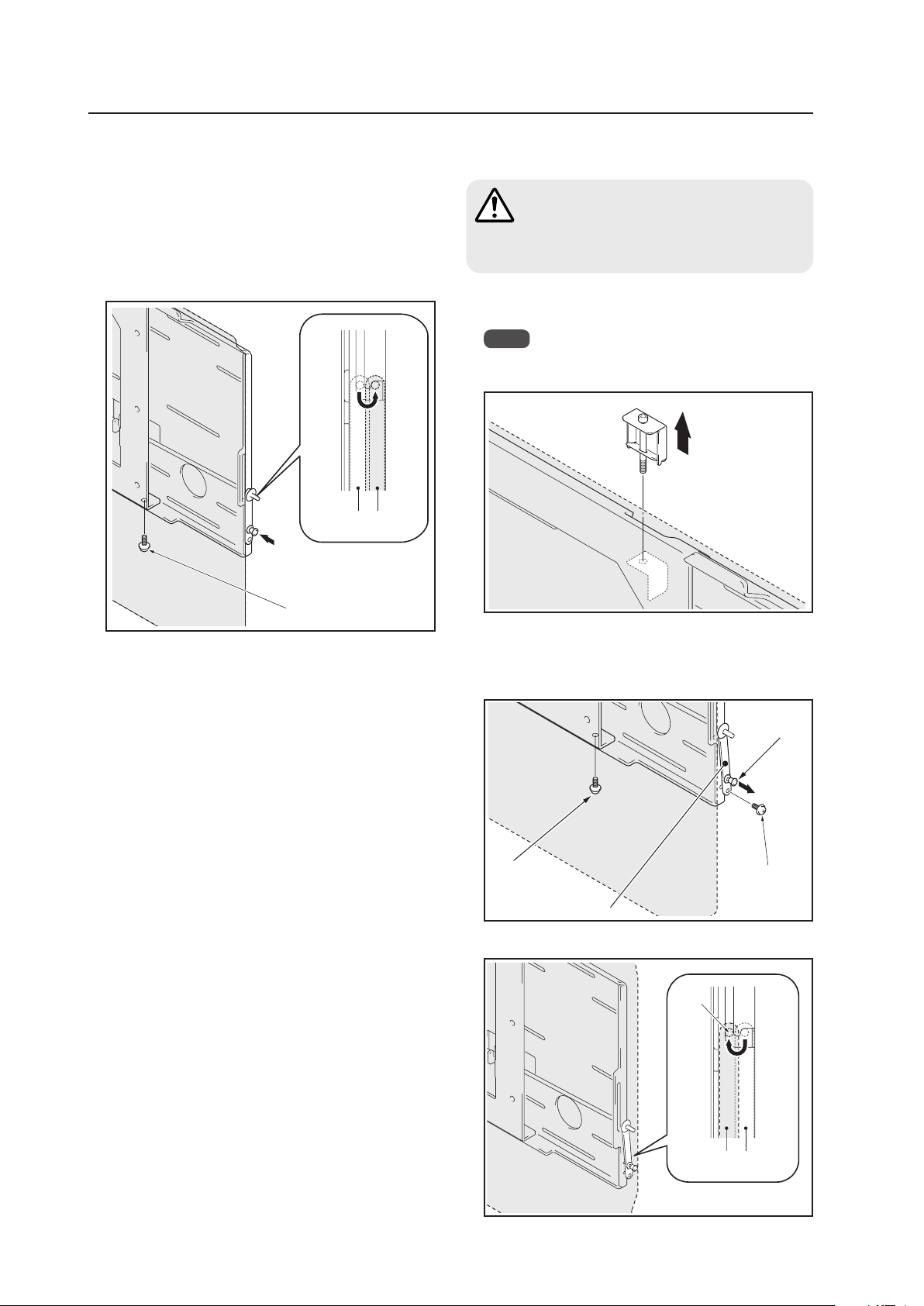
74
Wall Mount Unit: PDK-WM01
8 With the lock bar in the lock position, fix the lock plate
firmly in place with push rivet and the anchor screw
(M6 x 14 mm (9/16 inch)) (1 location: left and right sides)
removed in step 1 (1 location: left and right sides).
• If there are speakers installed on both sides
Fix in place with the anchor screw (M6 x 14 mm (9/
16 inch)) removed in step 1 (*1).
Lock bar in the lock
position.
Anchor screw (*1)
Unlocked
position
Locked
position
4.7.4 When removing the Plasma Display
Before beginning this procedure, turn off the
power to the Plasma Display and peripheral
devices. Remove the power plugs from the
outlets. Also remove connecting cables if
necessary.
2 Remove the push rivet and anchor screws that are
holding the lock plate. Then, remove the anchor
screws that are holding the PDP metal fitting (2
locations on the left and right).
Anchor screw
Push rivet
Lock plate
Anchor screw
3 Unlock the lock bar (2 locations on the left and right).
Lock
bar
Set the lock bar in its
unlocked position
Unlocked
position
Locked
position
Caution
1 Loosening the screw on the tilt adjustment metal
fitting.
Note
Removing the Plasma Display without removing the
tilt adjustment metal fitting (may scratch the wall).
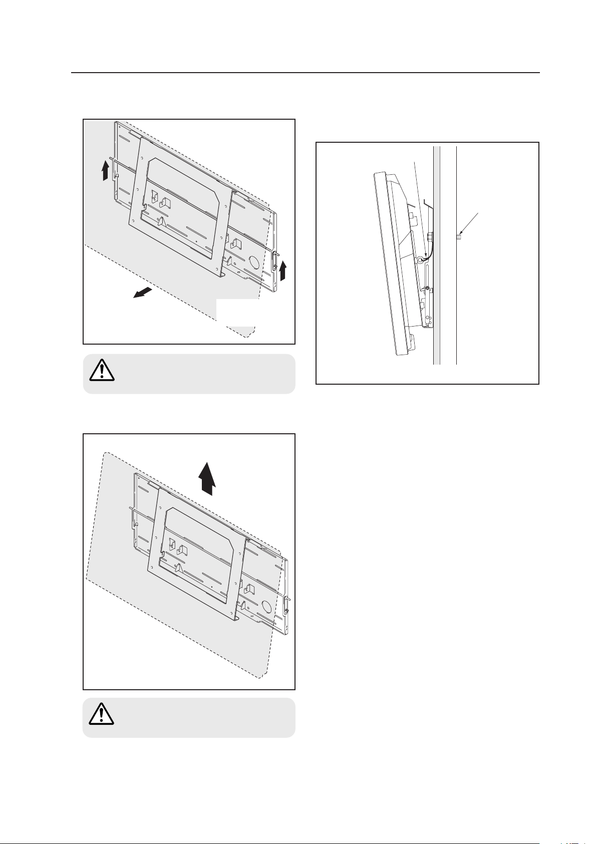
75
Wall Mount Unit: PDK-WM01
4 Raise the lock bar then pull the bottom of the Plasma
Display forward.
Pull out the bottom of
the Plasma Display.
5 Raise to remove the Plasma Display.
Raise and remove the Plasma Display.
Pull out the bottom of the Plasma Display
very carefully so that the hook on the PDP
side metal fitting is not displaced.
Always have at least 2 people manage this
task.
Raise the lock bar
(either the left or the
right side).
Caution
Caution
(Precautions when installing the hardware)
Firmly attach the safety wire to the attachment hole on
the Plasma Display. Anchor it firmly to the wall with a
bolt that extends through the structural wall.
Safety wire
Bolt
Decorative panel/structural wall

76
Ceiling Mount Unit: PDK-5012
4.8 Ceiling Mount Unit: PDK-5012
4.8.1 Specifications
External dimensions ................. 1022 mm (W) × 1062 mm (H) × 300 mm (D)
(40-1/4 in. (W) × 41-3/4. (H) × 11-3/4 in. (D))
(mounting hardware and Plasma Display)
Weight ....................................... 14.5 kg (32.0 lbs.) (mounting hardware only)
45.0 kg (99.2 lbs.) (mounting hardware and Plasma Display)
Adjustable range of angles ...... Horizontal to 25 degrees below horizontal, 45 degrees left/right
Material...................................... Steel pipe for general structure (STKM-R), STK, SPHC
Finish.......................................... Semi-matte black paint (Original Pioneer color)
Package dimensions ................. 1035 (W) × 360 (H) × 540 (D) mm
(40-3/4 (W) × 14-3/16 (H) × 21-1/4 (D) in.)
Package weight......................... 21.5 kg
(47.4 lbs.)
Layers of packing ...................... 10 layers
Components
PDP bracket ........................................................ × 1
Bolt M8 ............................................................... × 6
Special screw ...................................................... × 4
Hole cover ........................................................... × 1
Stencil (printed on the wrapping
material that is inside) ......................................... × 1
Installer's contact information (Japan only) ......... × 1
Operating instructions ......................................... × 1
The appropriate types of screws and other mounting hardware will depend on the strength and composition of the
ceiling. Purchase them separately.
✩ Operating Temperature Restrictions
• Ambient Temperature: 0 °C to 40 °C
✩ Operating Temperature Restrictions for Upside-Down Installations
(*1, *2)
• Ambient temperature: 0 °C to 40 °C
• Other factors: Maintain sufficient clearance between the display and the wall (at least 300 mm)
✩ Operating temperature restrictions for when the speaker system (PDP-S44-LR) is attached.
• Ambient temperature: 0 °C to 40 °C
*1
For this installation, set the ‘FAN CONTROL’ to ‘MAX’ as shown in “5.4.3 Adjustment and Setting in the Integrator Mode 14)
Cooling Fan Control Setting” (pg. 172).
*2
When INPUT2 has been selected, use input compatible signal up to 1280x1024 (60 Hz) at ambient temperature condition of 0 °C
to 35 °C.
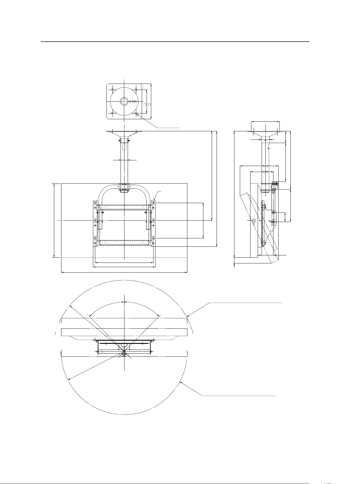
77
Ceiling Mount Unit: PDK-5012
4.8.2 External Dimensions
7 When using Plasma Display
(Unit: mm)
4-φ13.5X22
129
98
47 1062
110
67
80
277
(493)
329 100
φ
70
φ240.5
211
300
200
1022
758
980
496
(530)
300
R580
R510
45°
45°
610
φ60.5
This circle shows the path that the outermost
part of the Plasma Display follows when it is
rotated on a vertical axis after having been
titled sideways by 25°.
This circle shows the path that the outermost
part of the Plasma Display follows when it is
rotated on a vertical axis after having been titled
sideways by 25°.
Attachment
holes
(6 locations)
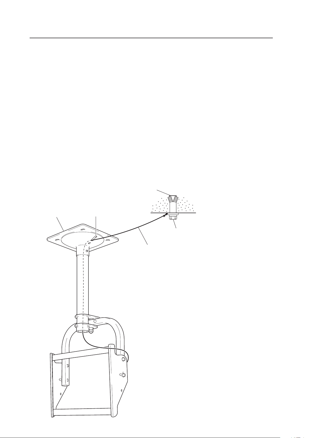
78
Ceiling Mount Unit: PDK-5012
Ceiling suspension hardware
Anchor
Foundation ceiling
Safety wire
Bolt
(NOTE) Safety wires serve as important backups in keeping the unit securely
mounted.
1 Firmly attach the safety wire to the Plasma Display attachment
hole and pass it through the supporting column.
2 Push the safety wire out of the hole on the ceiling mounting
hardware then anchor it firmly to the foundation ceiling with a bolt.
4.8.3 Installing the mounting hardware
1) Preparations
You will need the following tools. Make sure you have them at hand before beginning work.
• Phillips Head Screwdriver
• Hexagonal wrench (subtense 5 mm, for M6 bolts)
• Hexagonal wrench (subtense 6 mm, for M8 bolts)
You'll also need tools for ceiling work.
2) Install the mounting hardware
Select the installation site. Apply the supplied pattern to the ceiling, drill the holes, then mount the ceiling suspension
hardware. The appropriate types of screws and other display/mounting hardware depends upon the strength and
composition of the particular ceiling.
• Firmly tight all bolts.
• After attaching the mounting hardware but before mounting the Plasma Display, confirm the strength of the
mount portion of the ceiling.
• For additional safety, use the holes in the ceiling suspension hardware as shown.
[Use parts strong enough to support the weight of the display]
Hole
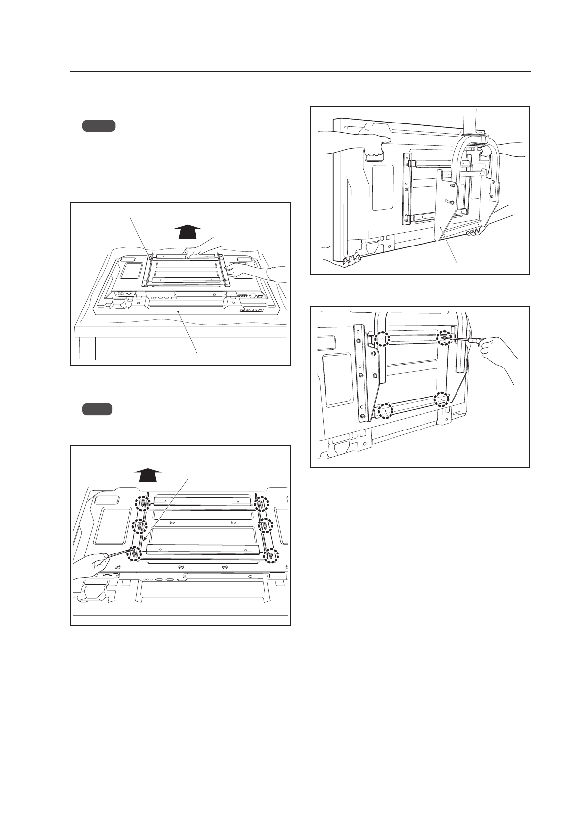
79
Ceiling Mount Unit: PDK-5012
4.8.4 Attach the Plasma Display
1 Attach the PDP bracket to the Plasma Display.
Notes
• Place a sheet or protective cover to protect the dis-
play from scratches or damage.
• Be sure to work on top of a flat table or similar sur-
face.
• Be careful that the PDP bracket is not upside down.
3 Attach the Plasma Display to the hanger.
4 Screw the Plasma Display to the hanger (at 4 locations).
PDP bracket
Top side of Plasma Display
Hanger
Plasma Display
Top side of Plasma Display
2 Fix the Plasma Display to the PDP bracket with screws
(6 locations).
Note
Be sure to use the holes shown on [43] to attach the
PDP-425CMX/PDP-42MXE10.
Hexagonal bolts
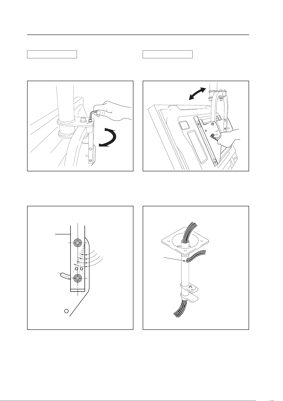
80
Ceiling Mount Unit: PDK-5012
5°
10°
15°
20°
4.8.5 Angle setup
Left-right Adjustment
You can adjust it 45° to the left or right by loosening the
top screw.
Set the desired angle then tighten the screw.
Vertical Adjustment
You can adjust its vertical angle by loosening the screws
on the left and right sides (maximum adjustment of 25°
downwards from the vertical position).
Set it to the desired angle while supporting the Plasma Display. Retighten the loosened screws on the left and right
sides. The hole on the side indicates the angle (5° units).
Detailed Angle Standard Diagram
Connecting cable
(when coming out of the top
of the supporting column)
Connecting cable
(when coming out of
the hole)
To the connector on the Plasma Display
Hole

81
Ceiling Mount Unit: PDK-5012

82
4.9 Mobile Cart: PDK-5014
4.9.1 Specifications
External dimensions ................. 1 1022 mm (W) × 1655 mm (H) × 710 mm (D)
(40-1/4 in. (W) × 65-5/32 in. (H) × 27 in. (D))
(when using the Plasma Display)
2 1022 mm (W) × 1655 mm (H) × 730 mm (D)
(40-1/4 in. (W) × 65-5/32 in. (H) × 28-3/4 in. (D))
(when using the Plasma Display)
Note) 1 : External dimensions of Serial No. 1 to 510 of PDK-5014
2 : External dimensions of Serial No. 511 and higher of PDK-5014
Weight ....................................... 43.0 kg (94.8 lbs.) (stand only)
73.5 kg (162 lbs.) (stand and Plasma Display)
Materials .................................... STKM (steel pipe) SPCC and SS41
Finish.......................................... Melamine baking finish (silver metallic)
Dimensions of packaging......... 1465 mm (W) × 200 mm (H) × 790 mm (D)
(57-7/8 in. (W) × 7-7/8 in. (H) × 31-3/32 in. (D))
(bracket, display stand section)
810 mm (W) × 295 mm (H) × 810 mm (D)
(31-7/8 in. (W) × 11-15/16 in. (H) × 31-7/8 in. (D))
(stand shelf, leg section)
Package weight......................... 38 kg (83.8 lbs.) (bracket, display stand section)
21 kg (46.3 lbs.) (stand shelf, leg section)
Layers of packing ...................... 10 layers
Components
Display stand ....................................................... × 1
Rear cover ........................................................... × 1
Leg base.............................................................. × 1
Bracket ................................................................ × 1
Stand shelf .......................................................... × 1
Hexagonal bored bolts (M8 × 20) ...................... × 10
Hexagonal bored bolts (M8 × 60) ........................ × 4
Hexagonal wrench .............................................. × 1
Washer ................................................................ × 4
Plate spring washer............................................. × 4
Mobile Cart: PDK-5014
✩ Operating Temperature Restrictions
• Ambient Temperature: 0 °C to 40 °C
✩ Operating temperature restrictions for when the speaker system (PDP-S44-LR) is attached.
• Ambient temperature: 0 °C to 40 °C
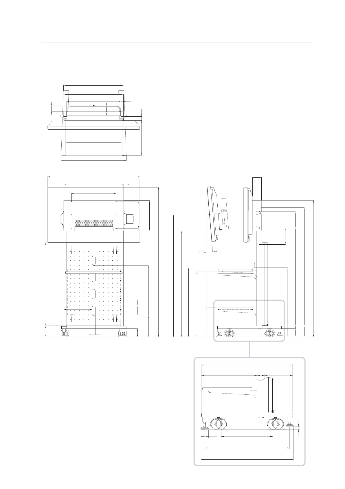
83
Mobile Cart: PDK-5014
4.9.2 External Dimensions
7 When using Plasma Display
(Units: mm)
(Stand shelf)
100
65
30
55
100
496
90
180
123.8
666.6
59
600
630
660
120
919.5 (Panel)
43
30
337
32.3
180
1084.5
1314
233.3
75
555
110
390
321.5
(Stand shelf installed at the lowest position)
721.5 (Stand shelf installation spacing 40 mm)
761.5 (Stand shelf installed at the highest position)
1350 (Center of the display screen when it is installed at the upper position)
1170 (Center of the display screen when it is installed at the lower position)
(673)
(723)
1022
300
35
312.5
1655
1510
765
(Stand shelf)
1 440
2 430
1 220
2 230
60
720
406
ø60
1 650
2 670
1 710
2 730
22
(Tilt angle)
5°
Note: Dimensions
1 : Compatible with Serial Nos. 1 to 510 of PDK-5014
2 : Compatible with Serial No. 511 and higher of PDK-5014
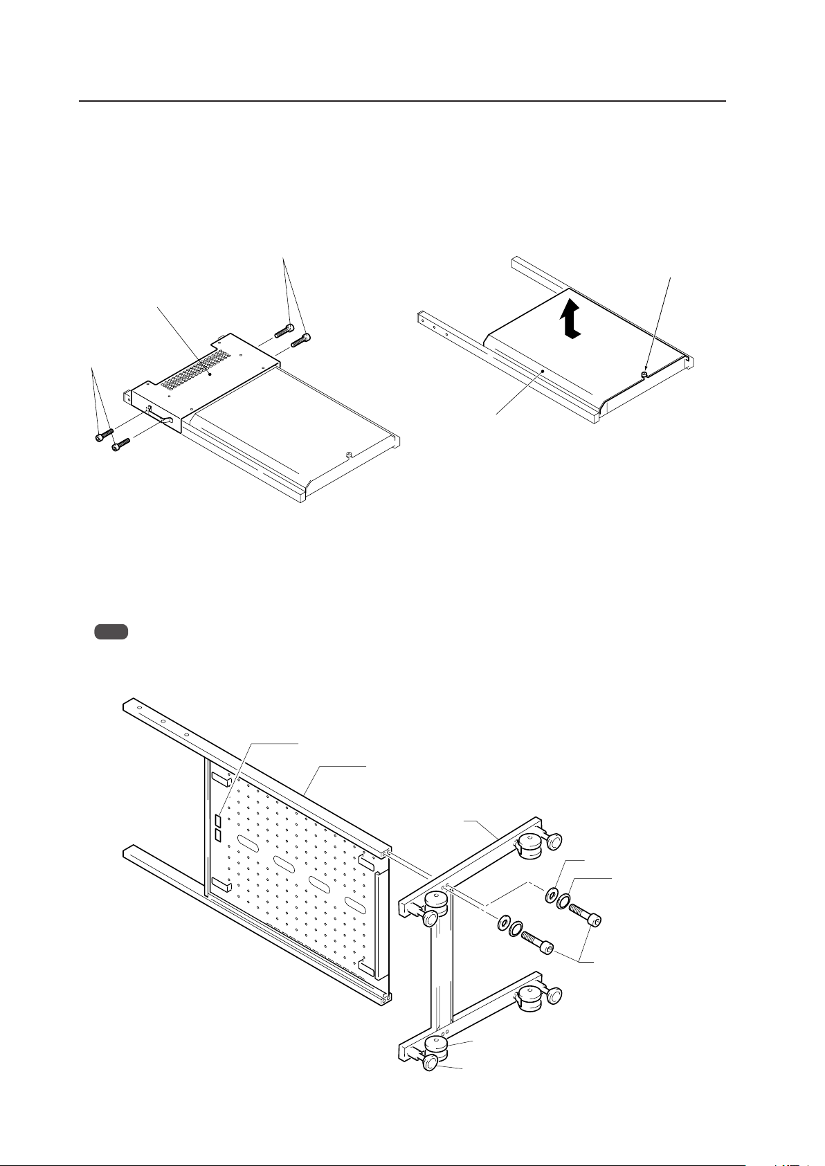
84
4.9.3 Disassembling the display stand
1 Remove the screws (four locations on the left and right
sides) then take off the bracket. For packing reasons,
the bracket is mounted at a different location then the
final installation location.
2 Remove the rear cover.
Mobile Cart: PDK-5014
Screws
Screws
Bracket
Rear cover
Loosen the
finger screws.
Do not take out the screws.
Back casters
Display stand
Leg base
Hexagonal bored bolts
(M8 × 60)
Washer
Plate spring washer
Support caster
Label
4.9.4 How to install
In order to ensure safety during installation, always be sure to work with more than two people.
1 Assemble the unit
Attach the leg base to the display stand using the hexagonal bored bolts (M8 × 60) so that the rear label faces
towards the back casters (shown in the figure below).
Note
For safety, alternately tighten each bolt two times or more until they are firmly fixed in place.
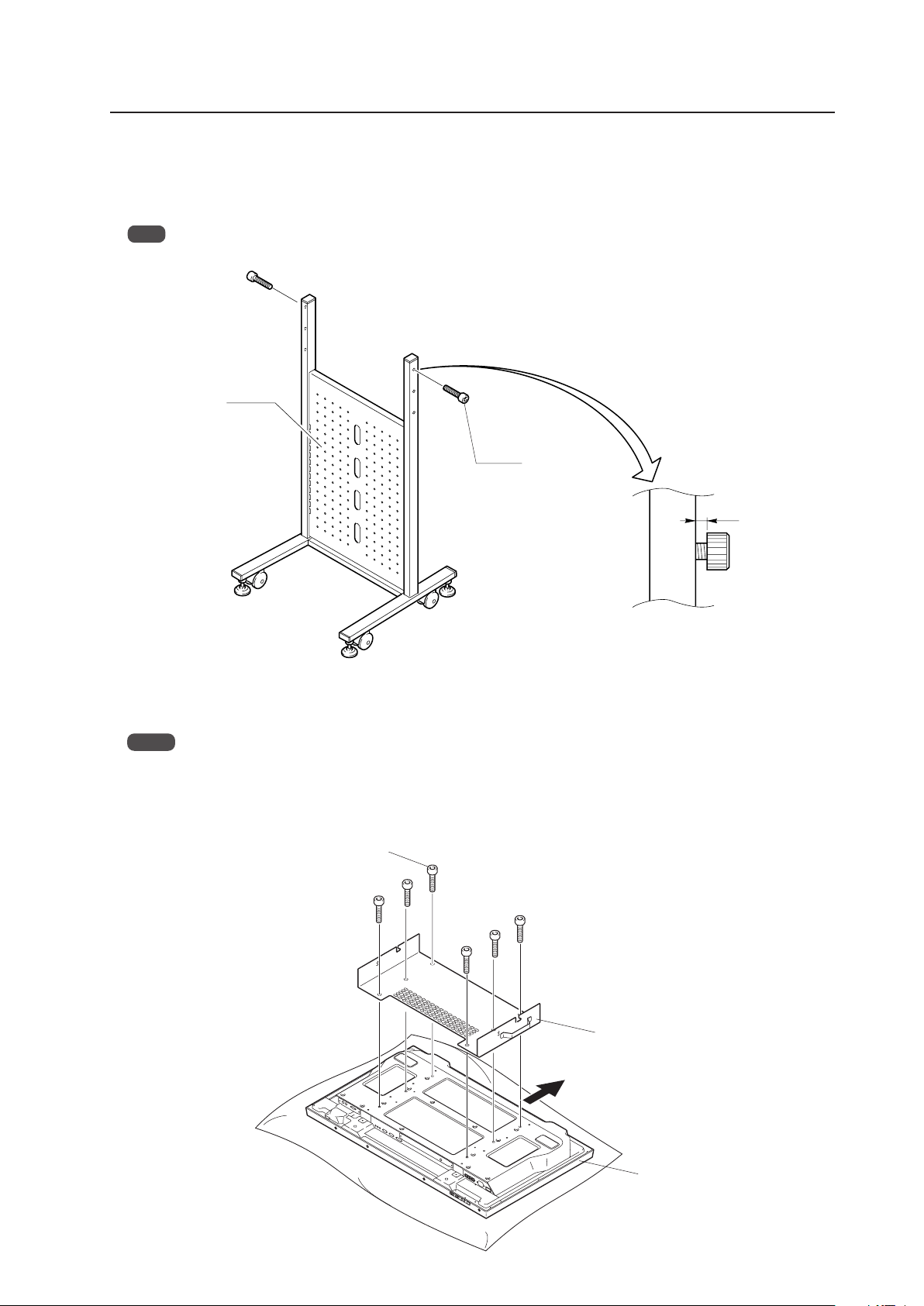
85
Mobile Cart: PDK-5014
Bracket
Plasma Display
Hexagonal bored bolts
(M8 × 20)
Top side of Plasma Display
2 Attach bracket bolts to display stand
Attach the hexagonal bored bolts (M8 × 20) to the display stand, being sure to leave a space of 5 to 6 millimeters
when doing so. These bolts may be attached at two different levels to allow a distance of 1350 mm or 1170 mm
from the floor to the center of the display panel.
Note
Do not place bracket bolts in the third set of screw holes from the top. These screw holes are used in Step 4 below.
Display stand
Hexagonal bored
bolts (M8 × 20)
5 to 6 mm
3 Attach bracket to Plasma Display
Using the hexagonal bored bolts (M8 × 20), attach the bracket to the rear of the Plasma Display by screwing the bolts
into the screw holes as the figure.
Notes
• The Plasma Display should be placed on a blanket or other soft surface to avoid scratching or otherwise damaging
the surface of the display.
• For safety, alternately tighten each bolt two times or more until they are firmly fixed in place.
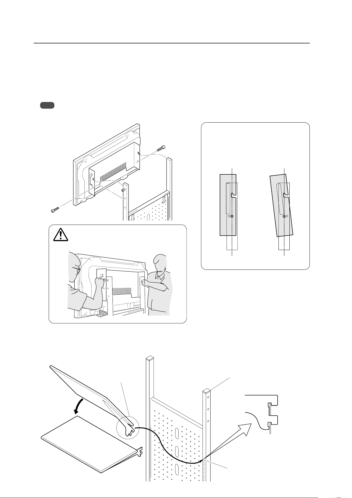
86
To safely attach the brackets to the support columns,
be sure to always have two people do this task as
shown in the drawing.
[Adjusting the angle of the Plasma Display
screen]
For easier viewing, angle it forwards by altering
the bracket attachment locations (5°).
5 Attach the stand shelf to the display stand
Hold the stand shelf at a diagonal to the display stand and insert the upper portion of the hooked end of the shelf
brackets into the slits located on the display stand. Return the shelf to a horizontal position to fix it into place (shelf
withstand load: 20 kg).
Mobile Cart: PDK-5014
5°
0°
Display stand
Slits
Hook
Insert the hook securely
into the slit.
Caution
4 Mount a panel on the stand once the bracket has been attached
1. Align the holes on the protruding portion of the bracket onto the left and right bolts attached to the display stand.
2. Using two hexagonal bored bolts (M8 x 20), attach the bracket to the left and right sides of the display stand.
Insert and screw the bolts into the screw holes located at the bottom of the protruding part of the bracket and the
screw holes of the display stand.
3. Screw the bolts of the protruding portion of the bracket firmly into place.
Note
For safety, alternately tighten each bolt two times or more until they are firmly fixed in place.
1,3
2
1,3
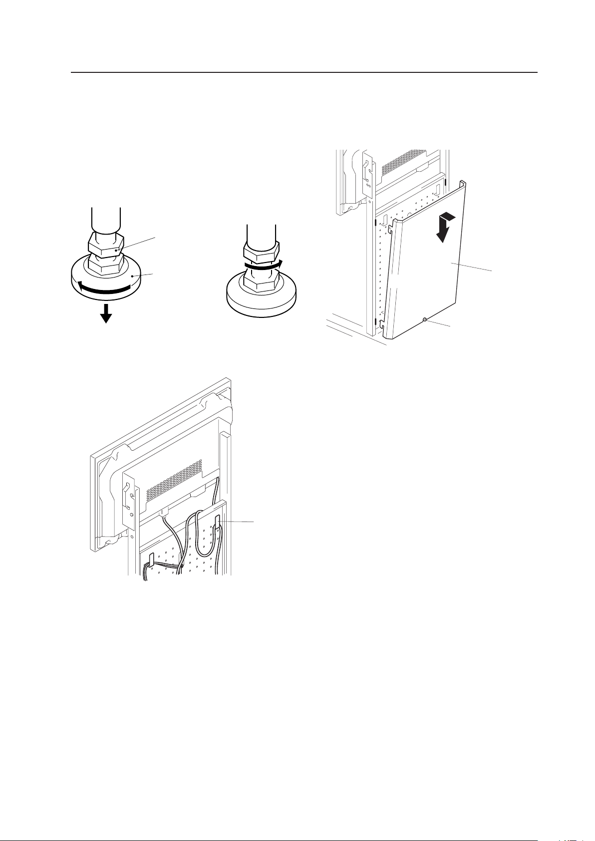
87
6 Adjust the support caster. When the mobile cart has
been placed into position, be sure to adjust the support
caster to fix into place.
1. Turn the support caster in the direction indicated by
the arrow until the bottom of the caster touches
the mounting surface.
2. Turn the nut at the top of the caster in the direction
indicated by the arrow to fix the caster into place.
7 Hang the cords from the hooks on the back of the
support columns.
8 Attach the rear cover. Attach the rear cover and fix it in
place by tightening the finger screws.
Be careful not to catch or pinch the cable with the rear
cover.
Mobile Cart: PDK-5014
Bottom of support
caster
Support caster nut
Hook
Rear cover
Finger screw

88
Speaker System: PDP-S44-LR/PDP-S52-LR
4.10 Speaker System: PDP-S44-LR/PDP-S52-LR
4.10.1 Specifications
External dimensions ................. 90 mm (W) × 610 mm (H) × 94.4 mm (D)
(3-1/2 in. (W) × 24-1/32 in. (H) × 3-22/32 in. (D))
When mounted to the Plasma Display:
1204 mm (W) × 610 mm (H) × 98 mm (D)
(48-1/32 in. (W) × 24-13/16 in. (H) × 4-1/16 in. (D))
Weight ....................................... 3.8 kg (8.4 lbs.)
34.3 kg (75.6 lbs.) (when mounted to the Plasma Display)
Dimensions of packaging......... 660 mm (W) × 260 mm (H) × 330 mm (D)
(27-5/16 in. (W) × 6-5/8 in. (H) × 12-17/32 in. (D))
Package weight......................... 6.2 kg (13.7 lbs.)
Cabinet....................................... Enclosed type, antimagnetic design
Used speakers (two-way method):
Woofer (for low tones) ....... 8 cm cone type
Tweeter (for high tones) .... 5 cm cone type
Nominal impedance ................. 6 Ω
Frequency Range ...................... 70 Hz to 20 000 Hz
Sensitivity.................................. 84 dB/W (at 1 m distance)
Permissible input:
Max. input ............................ 30 W
Rated input .......................... 10 W
Crossover frequency................. 250 Hz
Accessory parts (for 2 speakers)
Cushion ............................................................... × 2
Connection cord .................................................. × 2
Cord clamp .......................................................... × 2
Screw (M8).......................................................... × 4
Washer M8 (ø25) ................................................ × 2
Cautions
The sound may be irregular if there is a CRT type PC monitor close to the speakers. To prevent this, keep speakers
separated from the PC if you are using a CRT monitor.
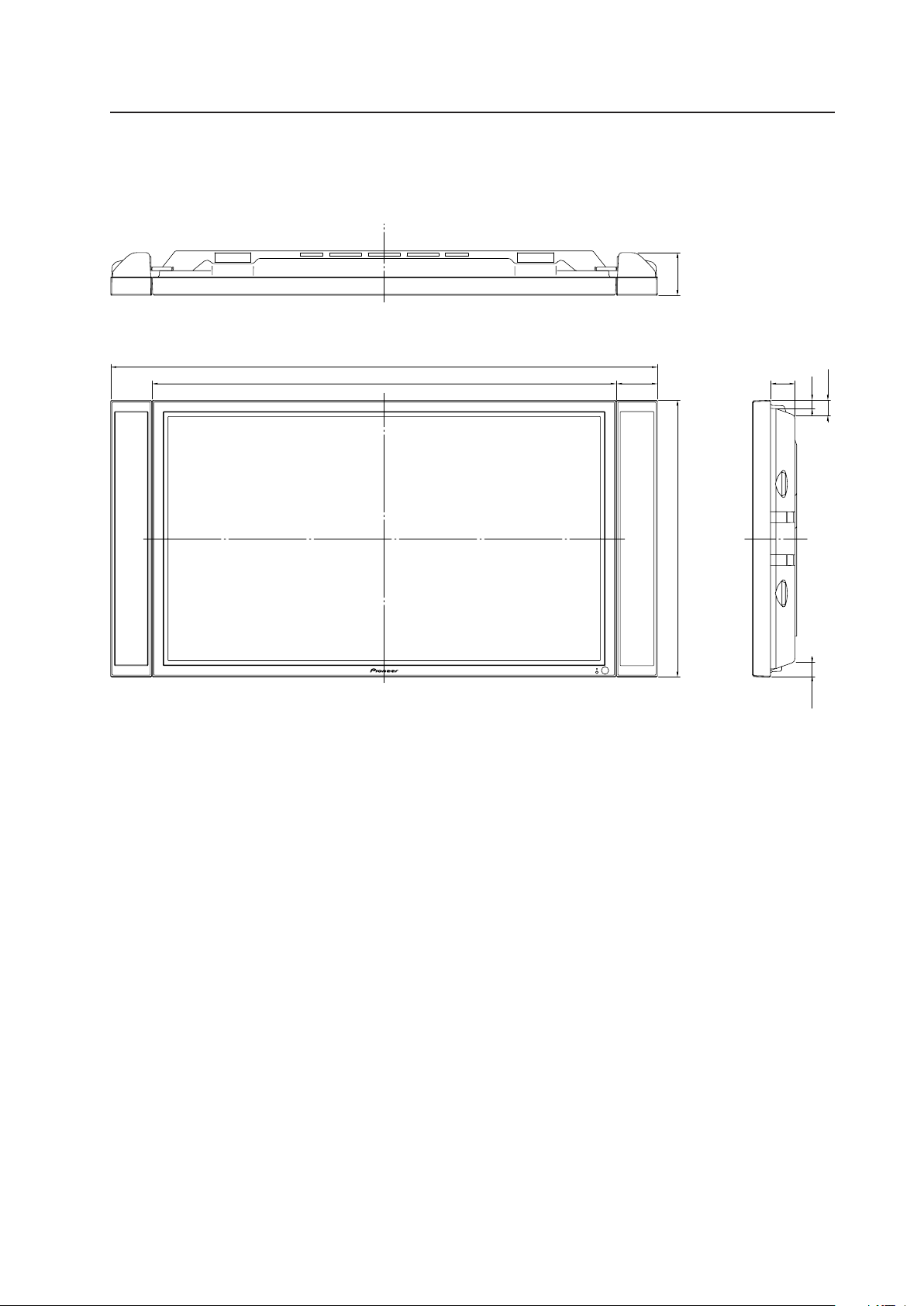
89
4.10.2 External Dimensions (when mounted to the Plasma Display)
(Units: mm)
Speaker System: PDP-S44-LR/PDP-S52-LR
These are the dimensions
of the side surface of the
speaker.
901022
1204
54
18
33.7
33.7
94.4
610
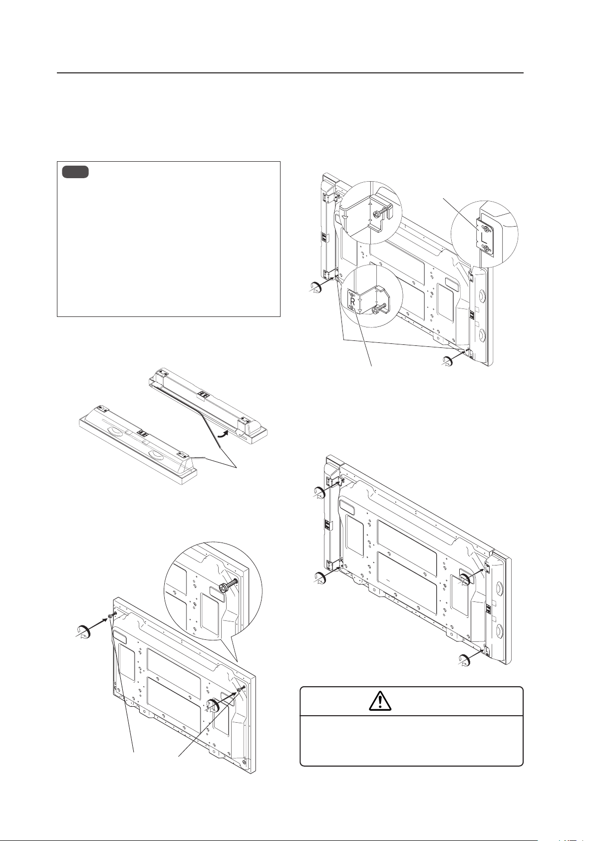
90
Speaker System: PDP-S44-LR/PDP-S52-LR
4.10.3 Installation on the Plasma Display
1) Installation procedure
Install the speaker system according to the steps (1)
through (4).
Notes
• The speakers are designed specifically for the left
(L) and right (R) sides of the Plasma Display. When
mounting them on the display, refer to the letters
(“L” and “R”) indicated on the speakers’ hooks.
• This speaker is of an antimagnetic design; however,
depending on its placement such as bringing the
speaker into the vicinity of a monitor other than a
Plasma Display, the speaker may cause irregular
noise or other effects. Should this occur, please move
the speaker away from the monitor.
(1) Attach the cushions to the sides of the speakers in the
positions indicated on the diagram.
Cushions
(2) Partially tighten the included screws (M8) in the screw
holes on the top of the display.
Screws (M8)
(3) Slide the hooks on the top of the speakers over the
partially tightened screws. Line up the hook holes on
the bottom of the speakers with the screw holes on
the bottom of the display then partially tighten the
screws.
Screws (M8)
(4) Fully tighten the four screws.
* Push the speaker against the display while tightening
the screw.
WARNING
When the speakers are installed on the display, do not
move the unit by lifting up on the speakers.
The display could fall and cause injury.
42R BOTTOM
42L UP
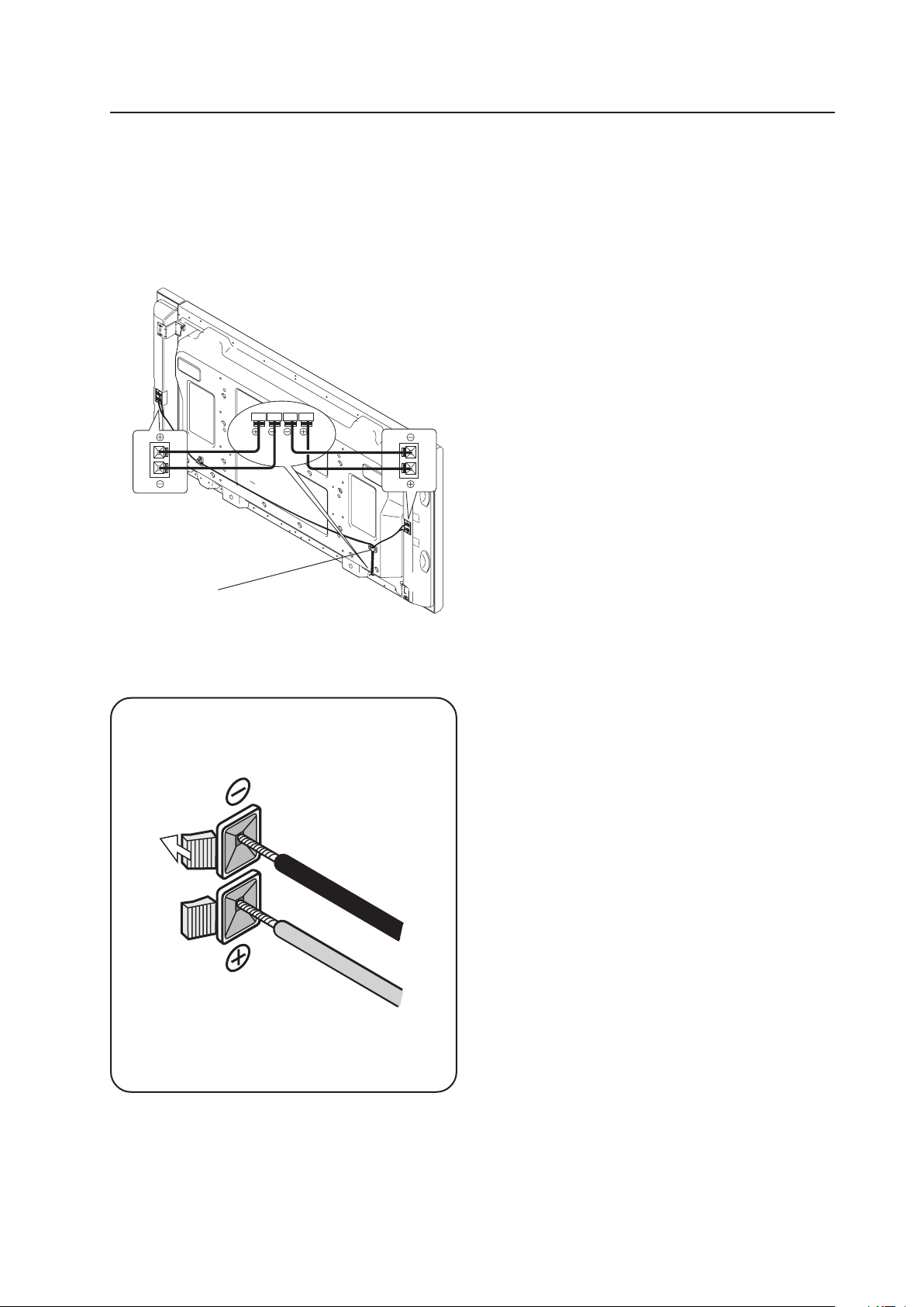
91
Speaker System: PDP-S44-LR/PDP-S52-LR
2) Connect the cords
(Turn off the power of all connected units before
connecting the cords.)
Connect the display’s SPEAKER R and L terminals with
the speakers terminals using the included connection
cords.
Cord Clamper
Peel off the protective tape from the back of
the clamper then mount the clamper in the
desired position. Clamp the cords together.
The conductor on each cord has a polarity ª ·.
Connect each conductor to the correct terminal.
While holding the button of each speaker terminal,
insert a cord conductor.
3) Care and Maintenance
When the cabinet gets dirty...
• Wipe with a lit-free, soft, dry cloth.
If the cabinet is heavily soiled, soak a cloth in a neutral
detergent solution, wring well, and wipe the cabinet.
Remove any remaining moisture by wiping with a dry
colth.
If you want to use a chemical cloth for cleaning, read
any caution information provided with the chemical cloth
product.
• Do not use solvent such as thinner or benzine for
cleaning. These chemical can damage the surface finish,
deteriorating or stripping the coating.
• To remove dust from the speaker nets, use a vacuum
cleaner’s. Avoid applying the vacuum cleaner hose
directly to the speakers without using a brush adapter
or using a nozzle adapter.
• To prevent damage to the cabinet and speaker nets, do
not scrach or hit them with hard objects. Also, do not
stab the speaker nets with sharp objects.
Do not apply volatile chemicals such as insecticide on
the cabinet. Avoid leaving a rubber or vinyl products in
contact with the cabinet for prolonged periods. The
surface finish can deteriorate or the coating may be
stripped off.

92
Before Beginning Adjustment/Setting
5.1 Before Beginning Adjustment
There are three methods for adjusting this display:
• Main control panel
• Remote control
• Personal computer (RS-232C control)
Carefully read and gain a good understanding of this section before beginning adjustment.
Items that apply only when a PDA-5003 or PDA-5004 is installed, are indicated with a ‘★’.
5.1.1 Operation Mode
This display is divided into the following four operating modes.
1
<PON>
2
<POF>STANDBY/ON
MENU
MENU
DISPLAY
DISPLAY
MENU
INPUT1 to 5
3
Integrator Mode
4
RS-232C Adjustment
Menu Mode
Power standby state
(Note 2)
Power management
standby state
ON indicator flashes
No input
Normal operation mode
(Note 1)
Press for 3
seconds or more.
indicates the operation modes and states
indicates button controls on the remote control or main-control panel
< > indicates controls by RS-232C commands
(Note 1) Refer to section 5.4.1, “About the Integrator Mode” (pg. 154).
(Note 2) Power management standby state exists only when power management is set.
1 Normal Operation Mode
This mode is for displaying signals.
In this mode the following basic controls are available:
• Switching to the power standby state
• Switching the input
• Switching the screen
• Adjusting the volume
• Muting the sound (remote control only)
• Setting the AUTO SET UP
• Applying the POINT ZOOM (remote control only)
• Accessing Multi screens (remote control only)
• Activating the menu mode or the integrator mode
In addition, some control via RS-232C commands is possible (Refer to section 5.5.5, “List of RS-232C Commands”
(pg. 198)).
2 Menu Mode
This mode is for adjusting the image quality, changing the screen position, and assigning various settings.
For details, refer to section 5.3, “Menu Mode” (pg. 114).
In this mode, it is possible to change adjustment data within a limited range. These adjustments are based on
values set in the integrator mode or RS-232C commands (to be described later).
For details, refer to section 5.3, “Menu Mode” (pg. 114).

93
Before Beginning Adjustments
3 Integrator Mode
This mode provides an adjustment function for integrator options.
This mode has white-balance adjustment and various detailed settings in addition to the items in the menu mode.
For details, refer to section 5.4, “Integrator Mode” (pg. 154).
4 RS-232C Adjustment
In this mode, a personal computer is used to perform various adjustments and settings.
There are some items that can only be configured in this mode.
For details, refer to section 5.5, “RS-232C Adjustment” (pg. 193).
5.1.2 Combined Use of the Remote Control, Main-control Panel, and RS-232C Commands
• The remote control and main-control panel can be operated together.
(Example) It is possible to access the Menu Mode using the main-control panel then perform an adjustment
using the remote control.
• With the remote-control (or main-control panel) buttons and RS-232C commands, the most resent control has priority.
In this mode, when performing some settings, an ID must be assigned at the start.
Note
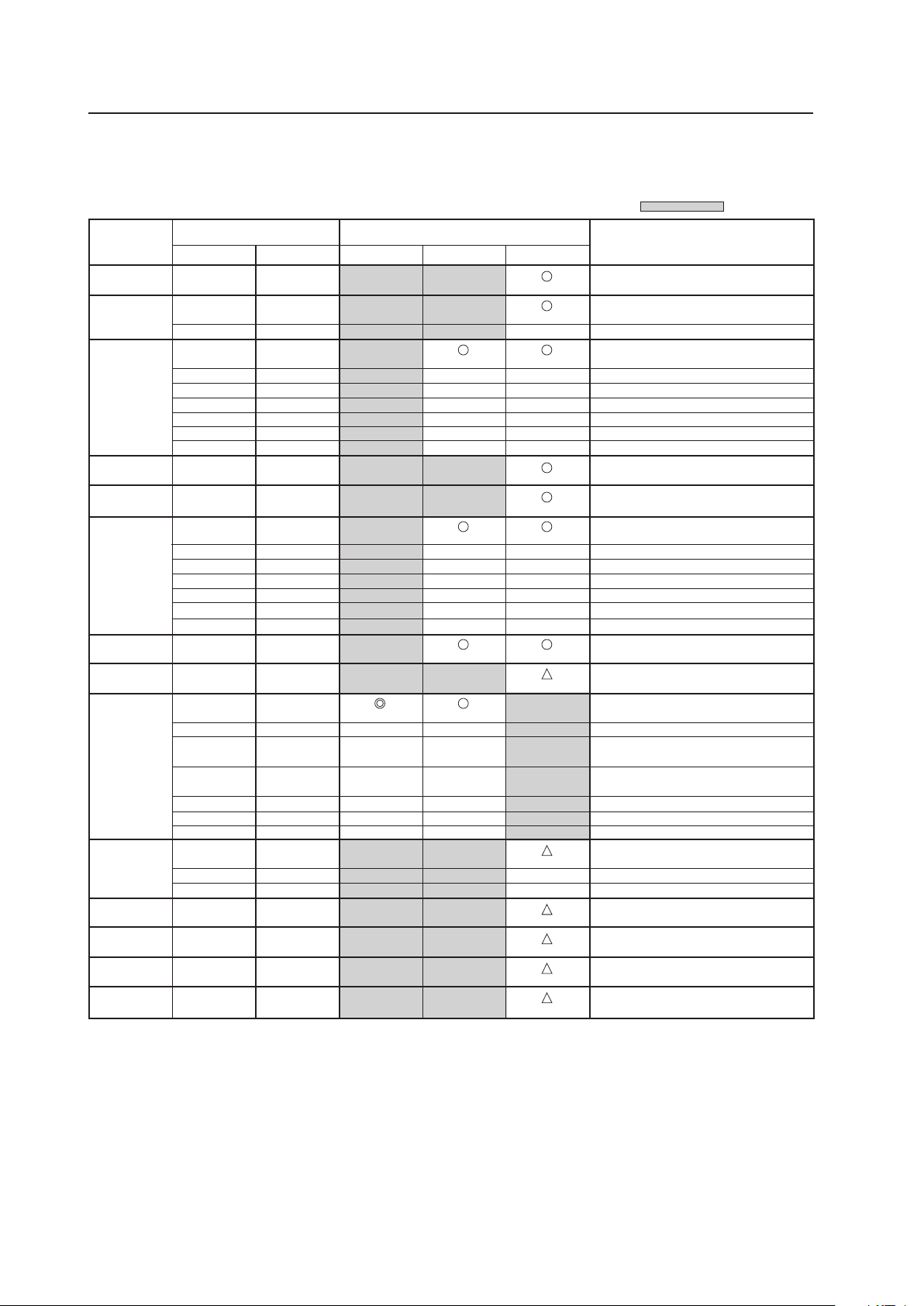
94
Before Beginning Adjustments
5.1.3 List of Input Correspondence Signals
1) Input correspondence signals (personal computer signals)
INPUT1
: Not available.
Resolution
(Dot x Line)
Vertical
DOT BY DOT
FULL
Remarks
Screen size (Dot x line)
Horizontal
4:3
Refresh rate
70.1 Hz
70.1 Hz
85.1 Hz
60 Hz
66.7 Hz
72.8 Hz
75 Hz
85 Hz
100.4 Hz
120.4 Hz
60 Hz
60 Hz
56 Hz
60 Hz
72 Hz
75 Hz
85 Hz
99.8 Hz
120 Hz
74.6 Hz
60 Hz
60 Hz
60 Hz
70 Hz
75 Hz
(74.9 Hz)
85 Hz
100.6 Hz
119.4 Hz
56 Hz
60 Hz
70 Hz
60 Hz
59.9 Hz
60 Hz
60 Hz
640x400
720x400
640x480
848x480
852x480
800x600
832x624
1360x765
1024x768
1280x768
1360x768
1376x768
1280x800
1280x854
Apple Macintosh 13”
I/O DATA
I/O DATA
I/O DATA
I/O DATA
I/O DATA
Apple Macintosh 16”
Work station (SGI)
( ) indicates Apple Macintosh 19”
I/O DATA
I/O DATA
I/O DATA
CVT
PC
1024x768
1024x768
±
1024x768
±
±
±
±
±
±
1024x768
1024x768
1024x768
±
±
±
±
±
±
1024x768
1024x768
1024x768
±
±
1024x768
1024x768
1024x768
1024x768
1024x768
±
±
±
±
±
±
31.5 kHz
31.5 kHz
37.9 kHz
31.5 kHz
35.0 kHz
37.9 kHz
37.5 kHz
43.3 kHz
51.1 kHz
61.3 kHz
31.0 kHz
31.7 kHz
35.2 kHz
37.9 kHz
48.1 kHz
46.9 kHz
53.7 kHz
63.0 kHz
75.7 kHz
49.7 kHz
47.7 kHz
48.4 kHz
49.7 kHz
56.5 kHz
60.0 kHz
(60.2 kHz)
68.7 kHz
80.5 kHz
95.6 kHz
45.1 kHz
47.8 kHz
56.1 kHz
47.7 kHz
48.3 kHz
49.7 kHz
53.1 kHz
768x768
±
±
±
±
±
±
768x768
±
±
±
±
±
±
768x768
768x768
±
±
±
±
±
±
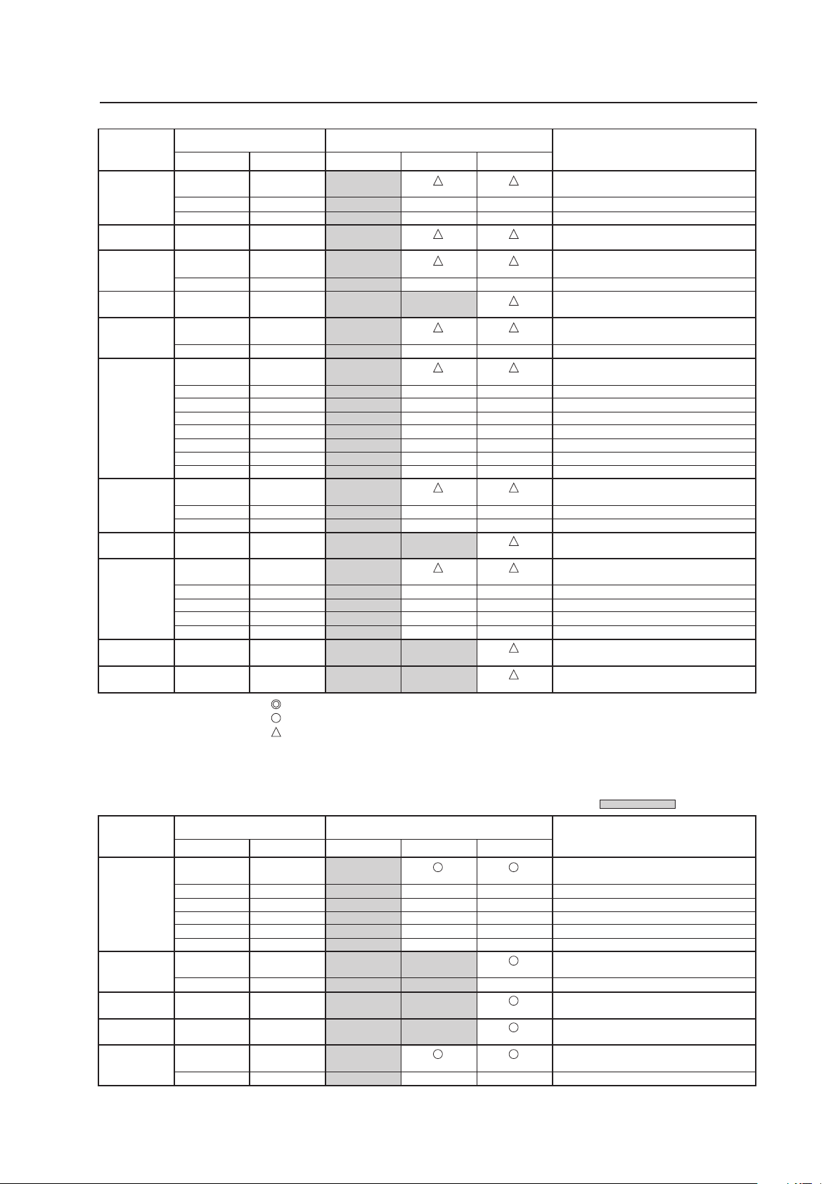
95
Before Beginning Adjustments
INPUT2
Resolution
(Dot x Line)
Vertical
DOT BY DOT
FULL
Remarks
Screen size (Dot x line)
Horizontal
4:3
Refresh rate
1152x864
1152x870
1152x900
1440x900
1280x960
1280x1024
1400x1050
1680x1050
1600x1200
1920x1200
1920x1200RB
60 Hz
72 Hz
75 Hz
75.1 Hz
66 Hz
76 Hz
60 Hz
60 Hz
85 Hz
60 Hz
60 Hz
71.2 Hz
72 Hz
75 Hz
76.1 Hz
85 Hz
100.1 Hz
60 Hz
75 Hz
85 Hz
60 Hz
60 Hz
65 Hz
70 Hz
75 Hz
85 Hz
60 Hz
60 Hz
53.7 kHz
64.9 kHz
67.5 kHz
68.5 kHz
61.8 kHz
71.7 kHz
56.0 kHz
60.0 kHz
85.9 kHz
64.0 kHz
64.6 kHz
75.1 kHz
78.1 kHz
80.0 kHz
81.1 kHz
91.2 kHz
108.5 kHz
65.3 kHz
82.3 kHz
93.9 kHz
65.3 kHz
75.0 kHz
81.3 kHz
87.5 kHz
93.8 kHz
106.3 kHz
74.6 kHz
74.0 kHz
768x768
±
±
768x768
768x768
±
768x768
±
768x768
±
±
±
±
±
±
±
768x768
±
±
768x768
±
±
±
±
1024x768
±
±
1024x768
1024x768
±
1024x768
1024x768
±
1024x768
±
±
±
±
±
±
±
1024x768
±
±
1024x768
1024x768
±
±
±
±
1024x768
1024x768
Apple Macintosh 21”
Sun Microsystems LO
Sun Microsystems HI
Apple Macintosh 17”
Work station (SGI)
Work station (EWS4800)
Work station (EWS4800)
Work station (HP)
Work station (SUN)
I/O DATA
CVT
CVT
: Optimal picture. Adjustment of picture position, refresh rate, phase etc., may be necessary.
: Picture will be enlarged but some fine detail will be hard to see.
: Simple reproduction. Fine detail will not be reproduced.
Resolution
(Dot x Line)
Vertical
DOT BY DOT
FULL
Remarks
Screen size (Dot x line)
Horizontal
4:3
: Not available.
Refresh rate
768x768
±
±
±
±
±
768x768
±
60 Hz
72.8 Hz
75 Hz
85 Hz
100.4 Hz
120.4 Hz
70.1 Hz
85.1 Hz
60 Hz
60 Hz
56 Hz
60 Hz
640x480
720x400
848x480
852x480
800x600
1024x768
±
±
±
±
±
1024x768
±
1024x768
1024x768
1024x768
±
31.5 kHz
37.9 kHz
37.5 kHz
43.3 kHz
51.1 kHz
61.3 kHz
31.5 kHz
37.9 kHz
31.0 kHz
31.7 kHz
35.2 kHz
37.9 kHz
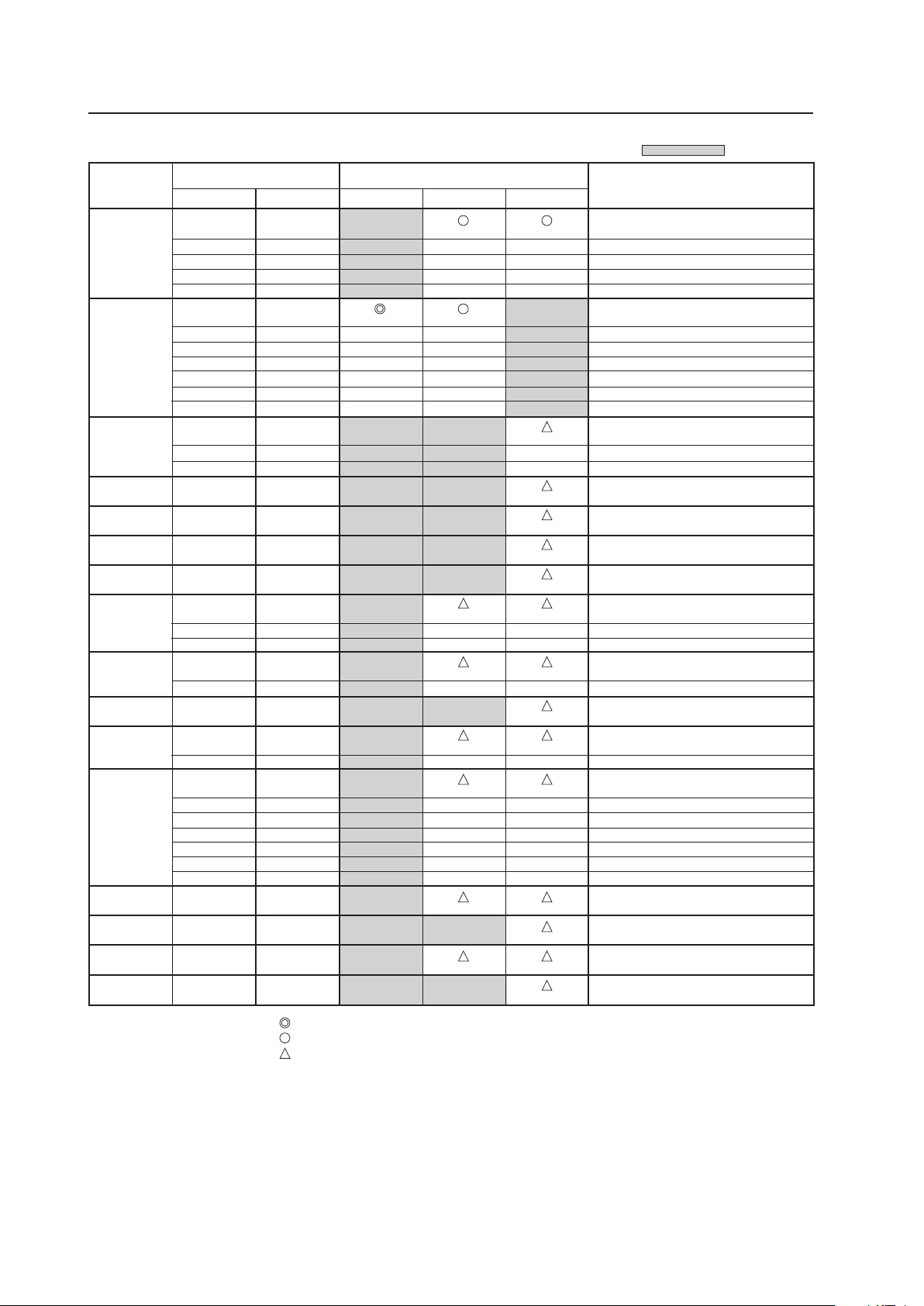
96
Before Beginning Adjustments
Resolution
(Dot x Line)
Vertical
DOT BY DOT FULL
Remarks
Screen size (Dot x line)
Horizontal
4:3
: Not available.
Refresh rate
800x600
1024x768
1280x768
1280x800
1280x854
1360x768
1376x768
1152x864
1152x900
1440x900
1280x960
1280x1024
1400x1050
1680x1050
1600x1200
1920x1200RB
72 Hz
75 Hz
85 Hz
99.8 Hz
120 Hz
60 Hz
60 Hz
70 Hz
75 Hz
85 Hz
100.6 Hz
119.4 Hz
56 Hz
60 Hz
70 Hz
60 Hz
60 Hz
60 Hz
59.9 Hz
60 Hz
75 Hz
66 Hz
72 Hz
76 Hz
60 Hz
60 Hz
85 Hz
60 Hz
60 Hz
71.2 Hz
72 Hz
76.1 Hz
75 Hz
85 Hz
60 Hz
60 Hz
60 Hz
60 Hz
48.1 kHz
46.9 kHz
53.7 kHz
63.0 kHz
75.7 kHz
48.4 kHz
49.7 kHz
56.5 kHz
60.0 kHz
68.7 kHz
80.5 kHz
95.6 kHz
45.1 kHz
47.8 kHz
56.1 kHz
49.7 kHz
53.1 kHz
47.7 kHz
48.3 kHz
53.7 kHz
67.5 kHz
61.8 kHz
64.9 kHz
71.7 kHz
56.0 kHz
60.0 kHz
85.9 kHz
64.0 kHz
64.6 kHz
75.1 kHz
78.1 kHz
81.1 kHz
80.0 kHz
91.2 kHz
65.3 kHz
1024x768
±
±
±
±
±
±
768x768
±
±
±
±
768x768
±
±
±
±
±
±
768x768
±
768x768
±
±
768x768
±
768x768
±
±
±
±
±
±
720x768
768x768
1024x768
±
±
±
±
1024x768
±
±
1024x768
1024x768
1024x768
1024x768
1024x768
±
1024x768
±
±
1024x768
1024x768
±
1024x768
±
±
±
±
±
±
1024x768
1024x768
1024x768
1024x768
Work station (SGI)
I/O DATA
I/O DATA
Work station (SUN)
Work station (SUN)
Apple Macintosh17”
Work station (SGI)
Work station (EWS4800)
Work station (EWS4800)
Work station (HP)
Work station (SUN)
CVT
: Optimal picture. Adjustment of picture position, refresh rate, phase etc., may be necessary.
: Picture will be enlarged but some fine detail will be hard to see.
: Simple reproduction. Fine detail will not be reproduced.
Note
In rare cases, the picture may not translate properly when switching between compatible signal formats on the output device (PC, etc.).
Should this happen, turn off the power and then turn it back on again.
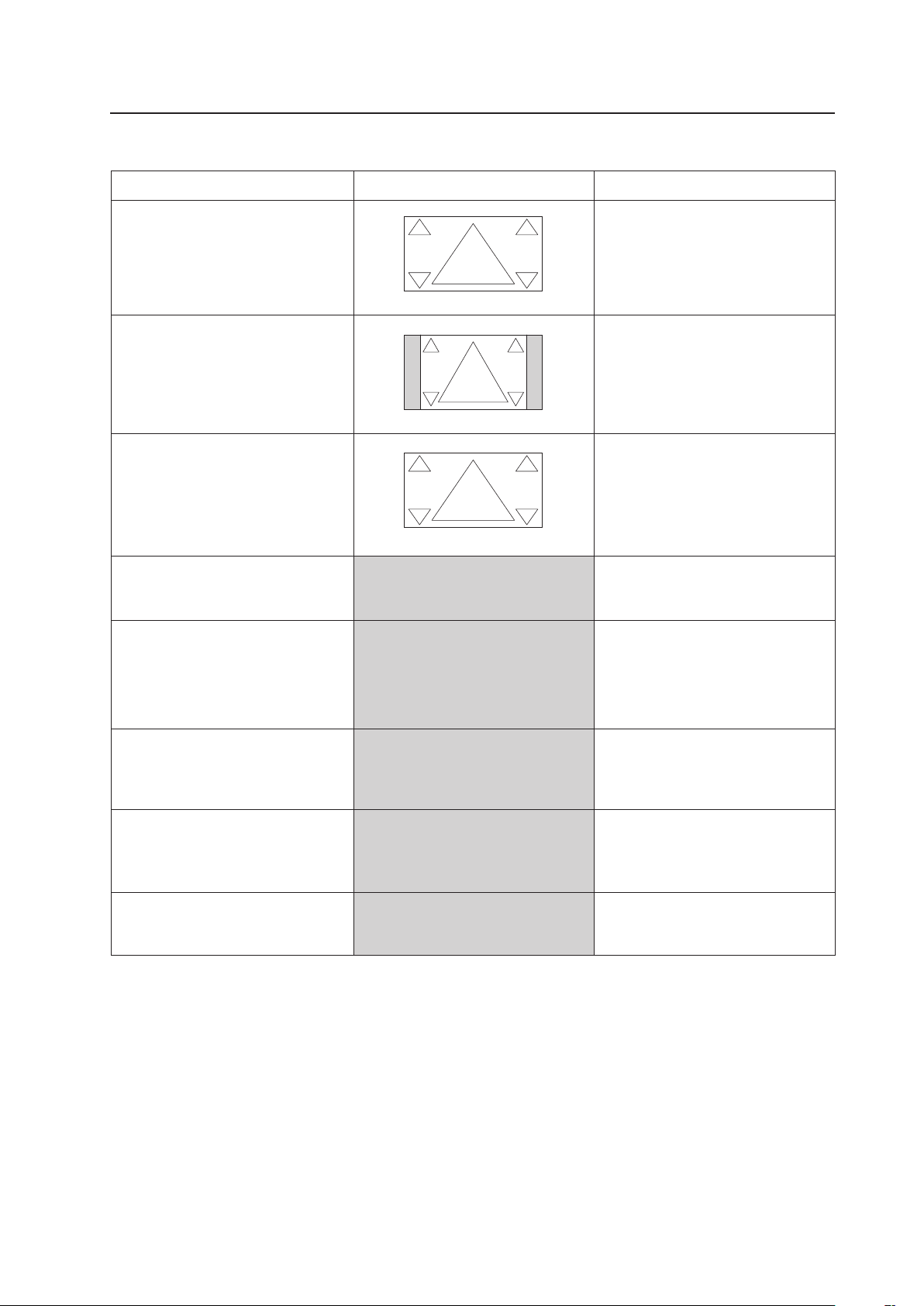
97
Before Beginning Adjustments
2) Screen size
Screen size
Personal computer signal
Remarks
FULL
This is for wide-screen video (squeeze) (For a
16:9 source, roundness is nearly accurate).
UNDERSCAN
This is used by a broadcast station and the
like for viewing the portion outside the
normal effective display range.
2.35:1
Displays 2.35:1 squeezed image full-screen
without black border. However, portions of
image at right and left edges are cut.
14:9
Displays expanded 4:3 screen image without
distortion.
WIDE
This is for reproducing the 4:3 portion of a
4:3 source or 16:9 source on the entire
screen (roundness near the center is nearly
accurate).
ZOOM
For a video signal, this is for a cinesco
(cinema scope) size video.
4:3
For a 4:3 source, roundness can be accurately
reproduced (In order to prevent burning of the
screen, this screen size should not be used
unless required).
DOT BY DOT
The input signal corresponds 1:1 with the
pixels of the Plasma Display for an accurate
reproduction.
Can be selected only during 1024x768
(XGA) signal input.
Is 5:4 during 1280x1024 (SXGA) signal
input.
Can be selected only during signal input
other than 1024x768 (XGA).
When selecting the underscan by switching
the screen size, please set to UNDERSCAN:
ON using PRO USE of the integrator mode.
100
100
100
100
100 100
100 100
100
100
100 100
Unit: % (percent)
• The screen size settings are stored in memory for each function and for each input signal. Up to eight (8) sizes can be stored in
memory for each function.
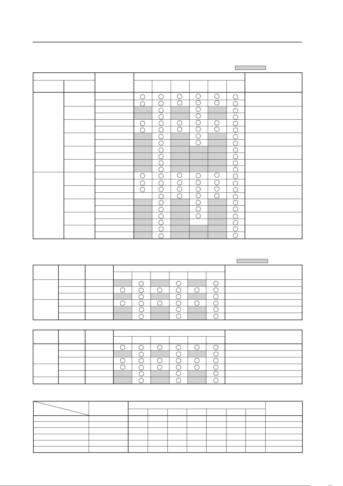
98
3) Input correspondence signals (video signals) ★ (Applicable only when a PDA-5003/PDA-5004 is installed.)
INPUT1, INPUT5 ★
: Not available.
15.625
28.13
31.25
37.50
56.20
62.50
15.734
31.5
33.75
45.0
67.5
Vertical
f
V (Hz)
Horizontal
fH (kHz)
Signal format
4:3 FULL
ZOOM
Remarks
50
60
Component
RGB
Component
RGB
Component
RGB
Component
RGB
Component
RGB
Component
RGB
Component
RGB
Component
RGB
Component
RGB
Component
RGB
Component
RGB
Screen size
*2
*2
*2
*2
*1
*1
*2
*2
625i (576i)/SDTV
1125i (1080i)/HDTV
625p (576p)/SDTV
750p (720p)/HDTV
1125p (1080p)/HDTV
1250p/HDTV
525i (480i)/SDTV
525p (480p)/SDTV
1125i (1080i)/HDTV
1125i (1035i)/HDTV
750p (720p)/HDTV
1125p (1080p)/HDTV
Refresh rate
WIDE
14:9 2.35:1
INPUT3 ★
Signal Format
S-Video (Y/C)
S-Video (Y/C)
S-Video (Y/C)
S-Video (Y/C)
S-Video (Y/C)
S-Video (Y/C)
4 : 3 FULL ZOOM WIDE CINEMA 14:9 2.35:1
Remark
Screen size
NTSC
PAL
SECAM
4.43 NTSC
PAL M
PAL N
‡ ‡ ‡ ‡ ‡ ‡ ‡
‡ ‡ ‡ ‡ ‡ ‡ ‡
‡ ‡ ‡ ‡ ‡ ‡ ‡
‡ ‡ ‡ ‡ ‡ ‡ ‡
‡ ‡ ‡ ‡ ‡ ‡ ‡
‡ ‡ ‡ ‡ ‡ ‡ ‡
*1: Can be selected from either [FULL1080i] or [FULL1035i]
*2: Some visual distortion may occur depending on the combination of connected components.
: Not available.
4:3 FULL
ZOOM
WIDE
14:9 2.35:1
Screen size
Remarks
Signal
format
Vertical
f
V (Hz)
Horizontal
f
H (kHz)
RGB
RGB
RGB
RGB
RGB
RGB
28.13
31.25
37.50
31.5
33.75
45.0
1125i(1080i)/HDTV
625p(576p)/SDTV
750p(720p)/HDTV
525p(480p)/SDTV
1125i(1080i)/HDTV
750p(720p)/HDTV
50
60
INPUT2 ★
4:3
FULL
ZOOM
WIDE
14:9 2.35:1
Screen size
Remarks
Vertical
f
V
(Hz)
Horizontal
f
H
(kHz)
Signal
format
RGB
RGB
RGB
RGB
RGB
RGB
15.6
56.25
15.8
31.5
67.5
62.5
625i(576i)/SDTV
1125p(1080p)/HDTV
525i(480i)/SDTV
525p(480p)x640 dot/SDTV
1125p(1080p)/HDTV
1250p/HDTV
50
50
60
The following signals are not formally supported but can be displayed (not recorded in EDID data).
*May not be displayed accurately depending on the connected device
Before Beginning Adjustments
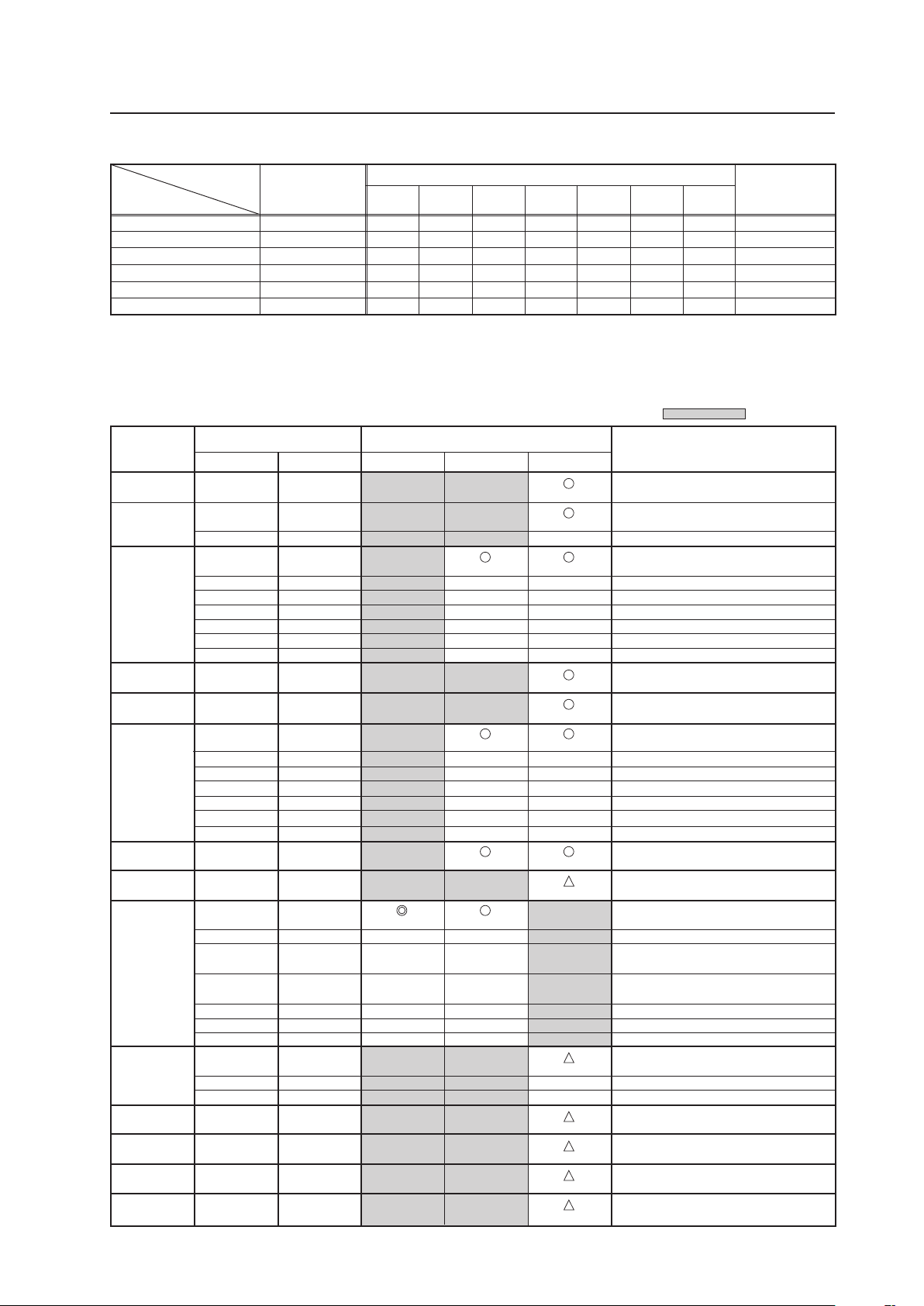
99
Before Beginning Adjustments
4) Input correspondence signals (personal computer signals)
INPUT1, INPUT5 ★ (Applicable only when a PDA-5003/PDA-5004 is installed.)
: Not available.
Resolution
(Dot x Line)
Vertical
DOT BY DOT
FULL
Remarks
Screen size (Dot x line)
Horizontal
4:3
Refresh rate
70.1 Hz
70.1 Hz
85.1 Hz
60 Hz
66.7 Hz
72.8 Hz
75 Hz
85 Hz
100.4 Hz
120.4 Hz
60 Hz
60 Hz
56 Hz
60 Hz
72 Hz
75 Hz
85 Hz
99.8 Hz
120 Hz
74.6 Hz
60 Hz
60 Hz
60 Hz
70 Hz
75 Hz
(74.9 Hz)
85 Hz
100.6 Hz
119.4 Hz
56 Hz
60 Hz
70 Hz
60 Hz
59.9 Hz
60 Hz
60 Hz
640x400
720x400
640x480
848x480
852x480
800x600
832x624
1360x765
1024x768
1280x768
1360x768
1376x768
1280x800
1280x854
Apple Macintosh 13”
I/O DATA
I/O DATA
I/O DATA
I/O DATA
I/O DATA
Apple Macintosh 16”
Work station (SGI)
( ) indicates Apple Macintosh 19”
I/O DATA
I/O DATA
I/O DATA
CVT
PC
1024x768
1024x768
±
1024x768
±
±
±
±
±
±
1024x768
1024x768
1024x768
±
±
±
±
±
±
1024x768
1024x768
1024x768
±
±
1024x768
1024x768
1024x768
1024x768
1024x768
±
±
±
±
±
±
31.5 kHz
31.5 kHz
37.9 kHz
31.5 kHz
35.0 kHz
37.9 kHz
37.5 kHz
43.3 kHz
51.1 kHz
61.3 kHz
31.0 kHz
31.7 kHz
35.2 kHz
37.9 kHz
48.1 kHz
46.9 kHz
53.7 kHz
63.0 kHz
75.7 kHz
49.7 kHz
47.7 kHz
48.4 kHz
49.7 kHz
56.5 kHz
60.0 kHz
(60.2 kHz)
68.7 kHz
80.5 kHz
95.6 kHz
45.1 kHz
47.8 kHz
56.1 kHz
47.7 kHz
48.3 kHz
49.7 kHz
53.1 kHz
768x768
±
±
±
±
±
±
768x768
±
±
±
±
±
±
768x768
768x768
±
±
±
±
±
±
INPUT4 ★
Signal Format
Composite
Composite
Composite
Composite
Composite
Composite
4 : 3 FULL ZOOM WIDE CINEMA 14:9 2.35:1
Remark
Screen size
NTSC
PAL
SECAM
4.43 NTSC
PAL M
PAL N
‡ ‡ ‡ ‡ ‡ ‡ ‡
‡ ‡ ‡ ‡ ‡ ‡ ‡
‡ ‡ ‡ ‡ ‡ ‡ ‡
‡ ‡ ‡ ‡ ‡ ‡ ‡
‡ ‡ ‡ ‡ ‡ ‡ ‡
‡ ‡ ‡ ‡ ‡ ‡ ‡
• ‘UNDERSCAN’ is for display-screen sizes other than those given in the table above. This size can be set using ‘PRO
USE’ in the integrator mode.
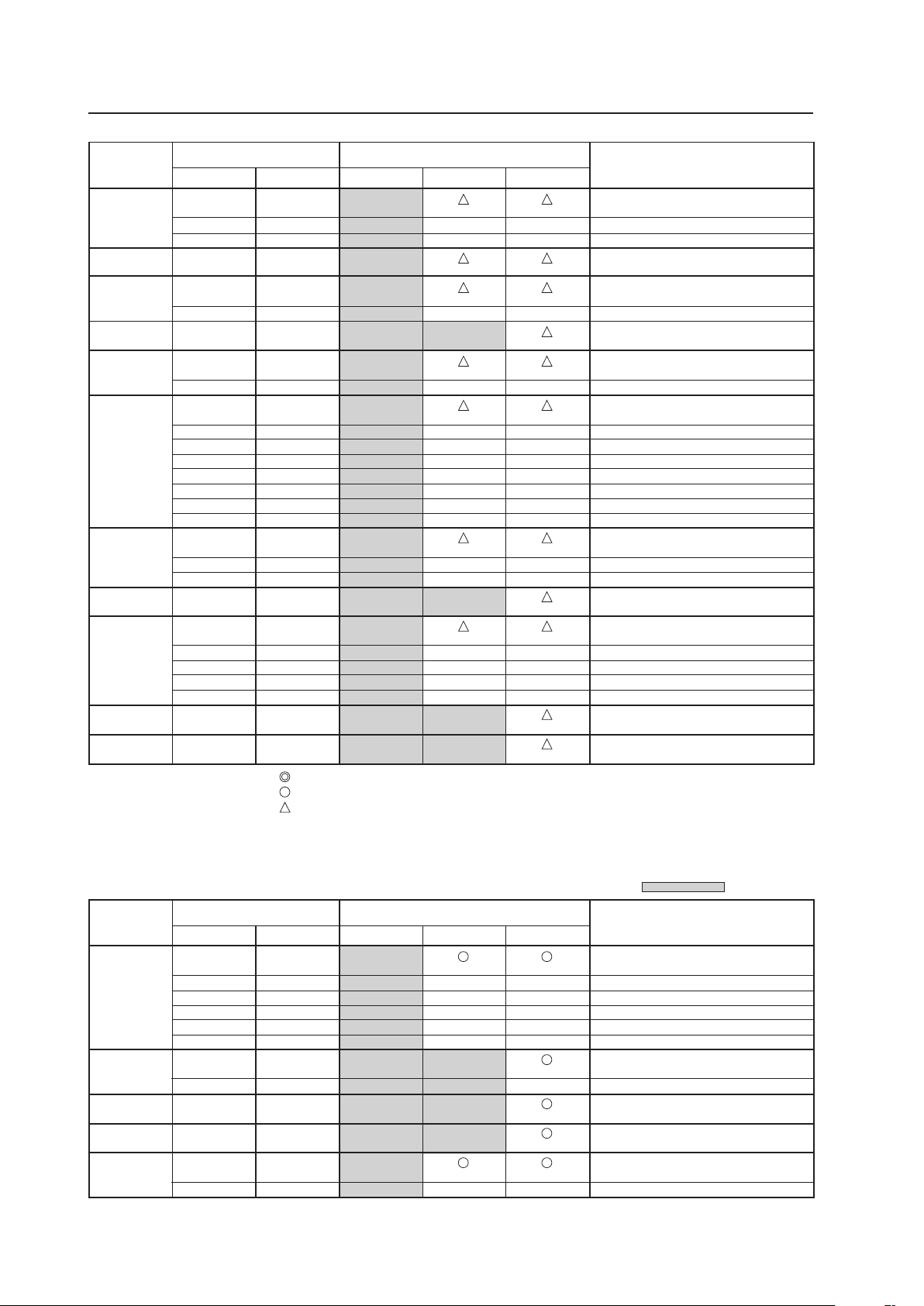
100
Before Beginning Adjustments
INPUT2
Resolution
(Dot x Line)
Vertical
DOT BY DOT
FULL
Remarks
Screen size (Dot x line)
Horizontal
4:3
Refresh rate
1152x864
1152x870
1152x900
1440x900
1280x960
1280x1024
1400x1050
1680x1050
1600x1200
1920x1200
1920x1200RB
60 Hz
72 Hz
75 Hz
75.1 Hz
66 Hz
76 Hz
60 Hz
60 Hz
85 Hz
60 Hz
60 Hz
71.2 Hz
72 Hz
75 Hz
76.1 Hz
85 Hz
100.1 Hz
60 Hz
75 Hz
85 Hz
60 Hz
60 Hz
65 Hz
70 Hz
75 Hz
85 Hz
60 Hz
60 Hz
53.7 kHz
64.9 kHz
67.5 kHz
68.5 kHz
61.8 kHz
71.7 kHz
56.0 kHz
60.0 kHz
85.9 kHz
64.0 kHz
64.6 kHz
75.1 kHz
78.1 kHz
80.0 kHz
81.1 kHz
91.2 kHz
108.5 kHz
65.3 kHz
82.3 kHz
93.9 kHz
65.3 kHz
75.0 kHz
81.3 kHz
87.5 kHz
93.8 kHz
106.3 kHz
74.6 kHz
74.0 kHz
768x768
±
±
768x768
768x768
±
768x768
±
768x768
±
±
±
±
±
±
±
768x768
±
±
768x768
±
±
±
±
1024x768
±
±
1024x768
1024x768
±
1024x768
1024x768
±
1024x768
±
±
±
±
±
±
±
1024x768
±
±
1024x768
1024x768
±
±
±
±
1024x768
1024x768
Apple Macintosh 21”
Sun Microsystems LO
Sun Microsystems HI
Apple Macintosh 17”
Work station (SGI)
Work station (EWS4800)
Work station (EWS4800)
Work station (HP)
Work station (SUN)
I/O DATA
CVT
CVT
: Optimal picture. Adjustment of picture position, refresh rate, phase etc., may be necessary.
: Picture will be enlarged but some fine detail will be hard to see.
: Simple reproduction. Fine detail will not be reproduced.
Resolution
(Dot x Line)
Vertical
DOT BY DOT
FULL
Remarks
Screen size (Dot x line)
Horizontal
4:3
: Not available.
Refresh rate
768x768
±
±
±
±
±
768x768
±
60 Hz
72.8 Hz
75 Hz
85 Hz
100.4 Hz
120.4 Hz
70.1 Hz
85.1 Hz
60 Hz
60 Hz
56 Hz
60 Hz
640x480
720x400
848x480
852x480
800x600
1024x768
±
±
±
±
±
1024x768
±
1024x768
1024x768
1024x768
±
31.5 kHz
37.9 kHz
37.5 kHz
43.3 kHz
51.1 kHz
61.3 kHz
31.5 kHz
37.9 kHz
31.0 kHz
31.7 kHz
35.2 kHz
37.9 kHz
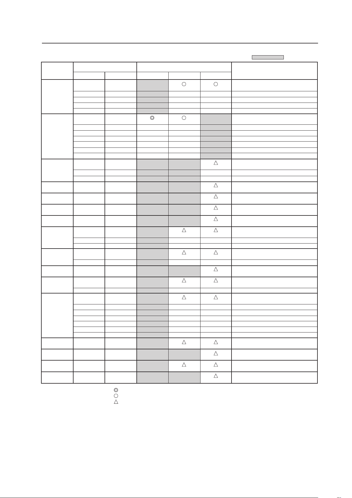
101
Before Beginning Adjustments
Resolution
(Dot x Line)
Vertical
DOT BY DOT FULL
Remarks
Screen size (Dot x line)
Horizontal
4:3
: Not available.
Refresh rate
800x600
1024x768
1280x768
1280x800
1280x854
1360x768
1376x768
1152x864
1152x900
1440x900
1280x960
1280x1024
1400x1050
1680x1050
1600x1200
1920x1200RB
72 Hz
75 Hz
85 Hz
99.8 Hz
120 Hz
60 Hz
60 Hz
70 Hz
75 Hz
85 Hz
100.6 Hz
119.4 Hz
56 Hz
60 Hz
70 Hz
60 Hz
60 Hz
60 Hz
59.9 Hz
60 Hz
75 Hz
66 Hz
72 Hz
76 Hz
60 Hz
60 Hz
85 Hz
60 Hz
60 Hz
71.2 Hz
72 Hz
76.1 Hz
75 Hz
85 Hz
60 Hz
60 Hz
60 Hz
60 Hz
48.1 kHz
46.9 kHz
53.7 kHz
63.0 kHz
75.7 kHz
48.4 kHz
49.7 kHz
56.5 kHz
60.0 kHz
68.7 kHz
80.5 kHz
95.6 kHz
45.1 kHz
47.8 kHz
56.1 kHz
49.7 kHz
53.1 kHz
47.7 kHz
48.3 kHz
53.7 kHz
67.5 kHz
61.8 kHz
64.9 kHz
71.7 kHz
56.0 kHz
60.0 kHz
85.9 kHz
64.0 kHz
64.6 kHz
75.1 kHz
78.1 kHz
81.1 kHz
80.0 kHz
91.2 kHz
65.3 kHz
1024x768
±
±
±
±
±
±
768x768
±
±
±
±
768x768
±
±
±
±
±
±
768x768
±
768x768
±
±
768x768
±
768x768
±
±
±
±
±
±
720x768
768x768
1024x768
±
±
±
±
1024x768
±
±
1024x768
1024x768
1024x768
1024x768
1024x768
±
1024x768
±
±
1024x768
1024x768
±
1024x768
±
±
±
±
±
±
1024x768
1024x768
1024x768
1024x768
Work station (SGI)
I/O DATA
I/O DATA
Work station (SUN)
Work station (SUN)
Apple Macintosh17”
Work station (SGI)
Work station (EWS4800)
Work station (EWS4800)
Work station (HP)
Work station (SUN)
CVT
: Optimal picture. Adjustment of picture position, refresh rate, phase etc., may be necessary.
: Picture will be enlarged but some fine detail will be hard to see.
: Simple reproduction. Fine detail will not be reproduced.
Note
In rare cases, the picture may not translate properly when switching between compatible signal formats on the output device (PC, etc.).
Should this happen, turn off the power and then turn it back on again.
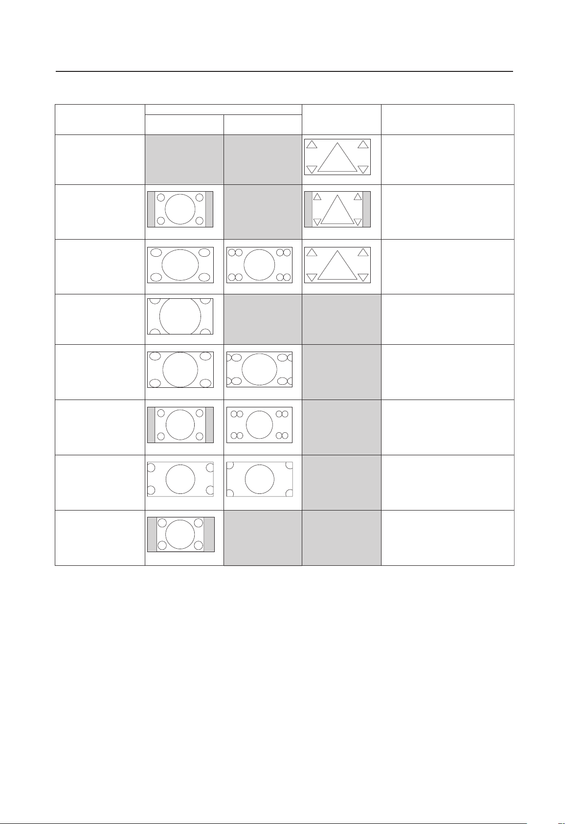
102
Before Beginning Adjustments
5) Screen size
When a video card is installed
Video signal 4:3 source
(NTSC, 625i, etc.)
Video signal 16:9 source
(750p, 1080i, etc.)
Screen size
Personal computer
signal
Remarks
FULL
This is for wide-screen video
(squeeze) (For a 16:9 source,
roundness is nearly accurate).
UNDERSCAN
This is used by a broadcast
station and the like for viewing
the portion outside the normal
effective display range.
2.35:1
Displays 2.35:1 squeezed image
full-screen without black border.
However, portions of image at
right and left edges are cut.
14:9
Displays expanded 4:3 screen
image without distortion.
WIDE
This is for reproducing the 4:3
portion of a 4:3 source or 16:9
source on the entire screen
(roundness near the center is
nearly accurate).
ZOOM
For a video signal, this is for a
cinesco (cinema scope) size video.
4:3
For a 4:3 source, roundness can
be accurately reproduced (In order
to prevent burning of the screen,
this screen size should not be
used when possible).
DOT BY DOT
The input signal corresponds 1:1
with the pixels of the Plasma
Display for an accurate
reproduction.
Can be selected only during 1024x768 (XGA) signal
input.
Is 5:4 during 1280x1024 (SXGA) signal input.
Can be selected only during signal input other than
1024x768 (XGA).
When selecting the underscan by switching the
screen size, please set to UNDERSCAN: ON using
PRO USE of the integrator mode.
100
100
100
100
100 100
10095 9595 95
95 95
100
100
100
100 100
95
95
95
95
95 95
95
95
73
73
95 95
90
90
100 100
100
100
100 100
100
100
72 72
90
90
Unit: % (percent)
84
84
74
74
74 74
95 95
74
74
74 74
• The screen size settings are stored in memory for each function and for each input signal. Up to eight (8) sizes can be stored in
memory for each function.
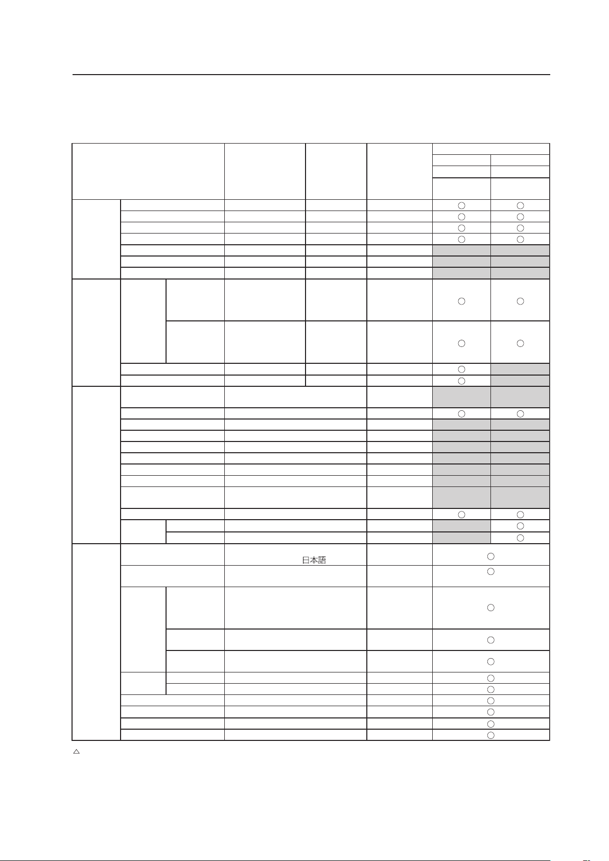
103
Before Beginning Adjustments
5.1.4 List of Adjustable and Settable Items
1) Menu Mode
7 PDP-425CMX/PDP-42MXE10
Variable range
(STEP)
Integrator
coefficien
(/STEP)
Factory setting
PDP-425CMX/PDP-42MXE10
INPUT1 INPUT2
PC signal PC signal
Analog RGB Digital RGB
PICTURE CONTRAST -30 to +30 X3
*1
, X4
*2
0
BRIGHTNESS -30 to +30 X1 0
H. ENHANCE 0 to +15 X1 0
V. ENHANCE 0 to +15 X1 0
COLOR -30 to +30 X1 0
TINT -30 to +30 X1 0
SHARPNESS -7 to +7 X1 0
SCREEN POSITION H -128 to +127
(for a PC signa)
-64 to +63
(for a video signa)
X1 0
V -128 to +127
(for a PC signa)
-64 to +63
(for a video signa)
X1 0
CLOCK -128 to +127 X1 0
PHASE -16 to +15 X1 0
SETUP COLOR TEMP. LOW-MID LOW-MIDDLE-
MID HIGH-HIGH
MIDDLE
POWER MGT. OFF-ON OFF
AUTO POWER OFF DISABLE-ENABLE DISABLE
DNR OFF-LOW-MIDDLE-HIGH MIDDLE
MPEG NR OFF-LOW-MIDDLE-HIGH LOW
CTI OFF-ON ON
PURECINEMA OFF-ON OFF
COLOR DECODING RGB-COMP.1-COMP.2 COMP.1/2
COLOR SYSTEM
AUTO-NTSC-PAL-SECAM-4.43NTSC-
PAL M-PAL N
AUTO
SIGNAL FORMAT
AUTO
AUTO
DVI SET UP PLUG/PLAY
PC
PC
BLACK LEVEL
LOW-HIGH LOW
OPTION
(NOTE 1)
LANGUAGE
ENGLISH-FRANÇAIS-ESPAÑOL-
DEUTSCH-ITALIANO-
ENGLISH
ENERGY SAVE AUTO-MODE1-MODE2-MODE3-
STANDARD
STANDARD
TIMER
SETTING
PRESENT
TIME
Hour: Disply for 24 hours
Day: SUNDAY-MONDAY-TUESDAY-
WEDNESDAY-THURSDAY-FRIDAY-
SATURDAY
-
DAYLIGHT
SAVIG TIME
ON-OFF OFF
PROGRAM
TIMER
ON-OFF OFF
SCREEN
MGT.
ORBITER
OFF-MODE1-MODE2-MODE3
OFF
SOFT FOCUS OFF-1 to 4 OFF
AUTO SETUP MODE INACTIVE-ACTIVE INACTIVE
AUTO FUNCTION
OFF-INPUT1
OFF
PIP DETECT ACTIVE-INACTIVE ACTIVE
SPLIT FREEZE OFF-S BY S-PIP OFF
: Cannot be set according to the signal.
*1: INPUT1 case
*2: INPUT2 case
(Note 1) The OPTION settings are common settings for all inputs.
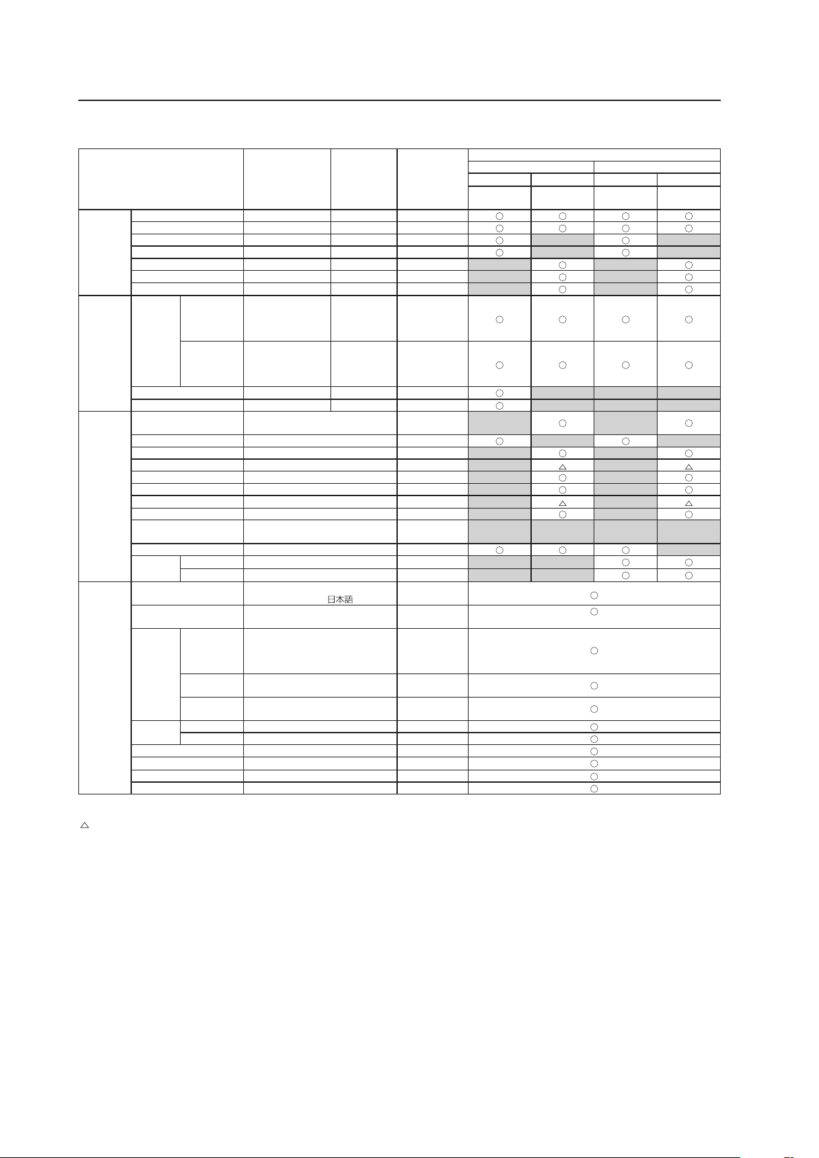
104
7 PDP-425CMX/PDP-42MXE10★
Variable range
(STEP)
Integrator
coefficien
(/STEP)
Factory setting
PDP-425CMX/PDP-42MXE10
INPUT1 INPUT2
PC signal
Video signal
★
PC signal
Video signal
★
Analog RGB
Component
RGB
Digital RGB
Digital
HDCP
PICTURE CONTRAST -30 to +30 X3
*1
, X4
*2
0
BRIGHTNESS -30 to +30 X1 0
H. ENHANCE 0 to +15 X1 0
V. ENHANCE 0 to +15 X1 0
COLOR -30 to +30 X1 0
TINT -30 to +30 X1 0
SHARPNESS -7 to +7 X1 0
SCREEN POSITION H -128 to +127
(for a PC signa)
-64 to +63
(for a video signa)
X1 0
V -128 to +127
(for a PC signa)
-64 to +63
(for a video signa)
X1 0
CLOCK -128 to +127 X1 0
PHASE -16 to +15 X1 0
SETUP COLOR TEMP. LOW-MID LOW-MIDDLE-
MID HIGH-HIGH
MIDDLE
POWER MGT. OFF-ON OFF
AUTO POWER OFF DISABLE-ENABLE DISABLE
DNR OFF-LOW-MIDDLE-HIGH MIDDLE
MPEG NR OFF-LOW-MIDDLE-HIGH LOW
CTI OFF-ON ON
PURECINEMA OFF-ON OFF
COLOR DECODING RGB-COMP.1-COMP.2 COMP.1/2
COLOR SYSTEM
AUTO-NTSC-PAL-SECAM-4.43NTSC-
PAL M-PAL N
AUTO
SIGNAL FORMAT
AUTO
AUTO
DVI SET UP PLUG/PLAY
PC-VIDEO
★
PC
BLACK LEVEL
LOW-HIGH LOW
OPTION
(NOTE 1)
LANGUAGE
ENGLISH-FRANÇAIS-ESPAÑOL-
DEUTSCH-ITALIANO-
ENGLISH
ENERGY SAVE AUTO-MODE1-MODE2-MODE3-
STANDARD
STANDARD
TIMER
SETTING
PRESENT
TIME
Hour: Disply for 24 hours
Day: SUNDAY-MONDAY-TUESDAY-
WEDNESDAY-THURSDAY-FRIDAY-
SATURDAY
-
DAYLIGHT
SAVIG TIME
ON-OFF OFF
PROGRAM
TIMER
ON-OFF OFF
SCREEN
MGT.
ORBITER
OFF-MODE1-MODE2-MODE3
OFF
SOFT FOCUS OFF-1 to 4 OFF
AUTO SETUP MODE INACTIVE-ACTIVE INACTIVE
AUTO FUNCTION
OFF-INPUT1-INPUT4
★
OFF
PIP DETECT ACTIVE-INACTIVE ACTIVE
SPLIT FREEZE OFF-S BY S-PIP OFF
★: Applicable only when a PDA-5003/PDA-5004 is installed.
: Cannot be set according to the signal.
*1: INPUT1 case
*2: INPUT2 case
(Note 1) The OPTION settings are common settings for all inputs.
Before Beginning Adjustments
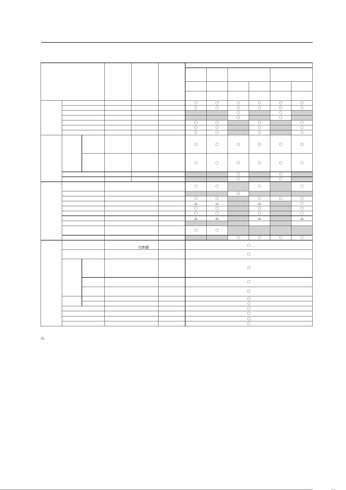
105
Before Beginning Adjustments
7 PDA-5003/PDA-5004
Variable range
(STEP)
Integrator
coefficien
(/STEP)
Factory
setting
PDA-5003/PDA-5004
INPUT3 INPUT4
INPUT5
(when PDA-5003 is
mounted)
INPUT5
(when PDA-5004 is
mounted)
Video
signal
Video
signal
PC signal
Video
signal
PC signal
Video
signal
S-Video Compsite
Analog
RGB
Component
RGB
Analog
RGB
Component
RGB
PICTURE CONTRAST -30 to +30 X3
*1
, X4
*2
0
BRIGHTNESS -30 to +30 X1
0
H. ENHANCE 0 to +15 X1
0
V. ENHANCE 0 to +15 X1
0
COLOR -30 to +30 X1
0
TINT -30 to +30 X1
0
SHARPNESS -7 to +7 X1
0
SCREEN POSITION H -128 to +127
(for a PC signa)
-64 to +63
(for a video signa)
X1
0
V -128 to +127
(for a PC signa)
-64 to +63
(for a video signa)
X1
0
CLOCK -128 to +127 X1
0
PHASE -16 to +15 X1
0
SETUP COLOR TEMP. LOW-MID LOW-MIDDLE-
MID HIGH-HIGH
MIDDLE
POWER MGT. OFF-ON OFF
AUTO POWER OFF DISABLE-ENABLE DISABLE
DNR OFF-LOW-MIDDLE-HIGH MIDDLE
MPEG NR OFF-LOW-MIDDLE-HIGH LOW
CTI OFF-ON ON
PURECINEMA OFF-ON OFF
COLOR DECODING RGB-COMP.1-COMP.2 COMP.1/2
COLOR SYSTEM
AUTO-NTSC-PAL-SECAM-
4.43NTSC-PAL M-PAL N
AUTO
SIGNAL FORMAT
AUTO
AUTO
OPTION
(NOTE 1)
LANGUAGE
ENGLISH-FRANÇAIS-ESPAÑOL-
DEUTSCH-ITALIANO-
ENGLISH
ENERGY SAVE AUTO-MODE1-MODE2-MODE3-
STANDARD
STANDARD
TIMER
SETTING
PRESENT
TIME
Hour: Disply for 24 hours
Day: SUNDAY-MONDAY-
TUESDAY-WEDNESDAY-
THURSDAY-FRIDAY-SATURDAY
-
DAYLIGHT
SAVIG TIME
ON-OFF OFF
PROGRAM
TIMER
ON-OFF OFF
SCREEN
MGT.
ORBITER OFF-MODE1-MODE2-MODE3 OFF
SOFT FOCUS OFF-1 to 4 OFF
AUTO SETUP MODE INACTIVE-ACTIVE INACTIVE
AUTO FUNCTION
OFF-INPUT1-INPUT4
★
OFF
PIP DETECT ACTIVE-INACTIVE ACTIVE
SPLIT FREEZE OFF-S BY S-PIP OFF
★: Applicable only when a PDA-5003/PDA-5004 is installed.
: Cannot be set according to the signal.
*1: INPUT5 case
*2: INPUT3 or INPUT4 cases
(Note 1) The OPTION settings are common settings for all inputs.
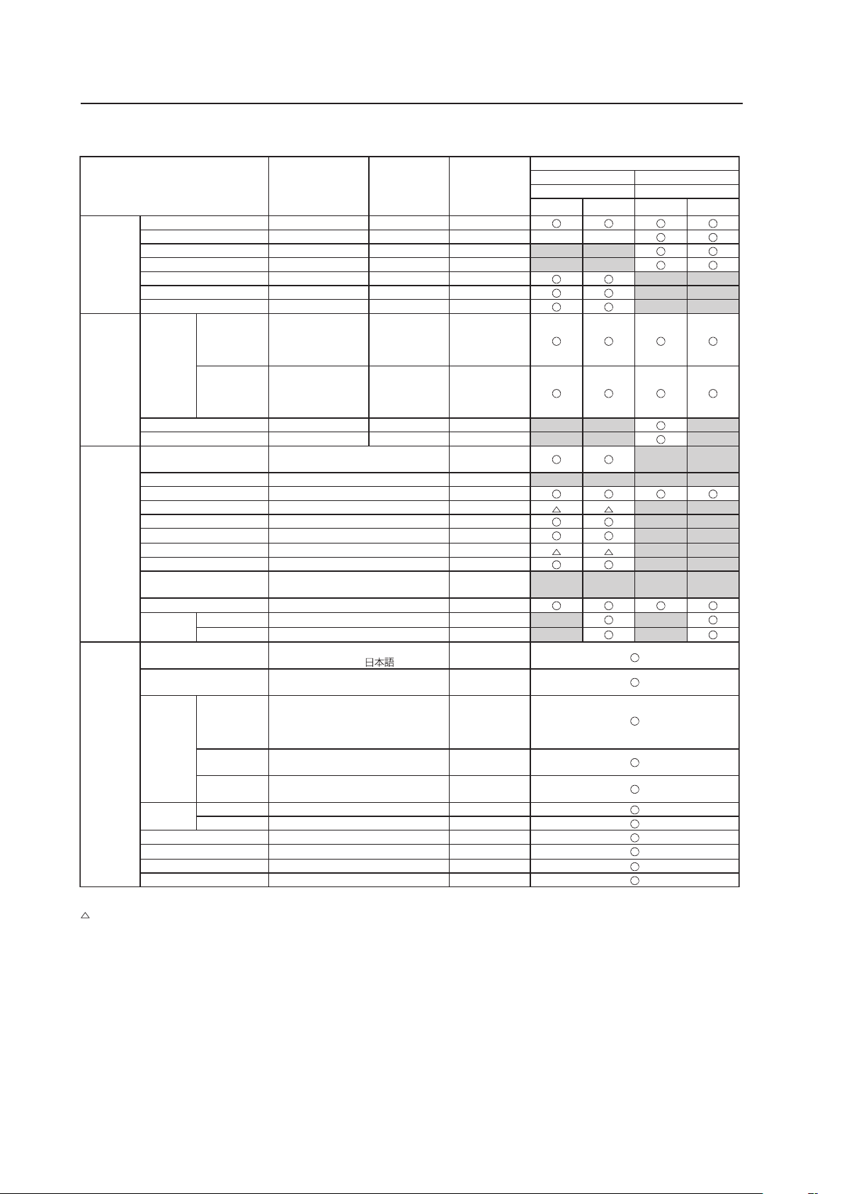
106
Before Beginning Adjustments
7 Video card other than PDA-5003/PDA-5004
Variable range
(STEP)
Integrator
coefficien
(/STEP)
Factory setting
Video card other than PDA-5003/PDA-5004
INPUT3 to 5 INPUT3 to 5
Video signal PC signal
Analog Digital Analog Digital
PICTURE CONTRAST -30 to +30 X3
*1
, X4
*2
0
BRIGHTNESS -30 to +30 X1 0
H. ENHANCE 0 to +15 X1 0
V. ENHANCE 0 to +15 X1 0
COLOR -30 to +30 X1 0
TINT -30 to +30 X1 0
SHARPNESS -7 to +7 X1 0
SCREEN POSITION H -128 to +127
(for a PC signa)
-64 to +63
(for a video signa)
X1 0
V -128 to +127
(for a PC signa)
-64 to +63
(for a video signa)
X1 0
CLOCK -128 to +127 X1 0
PHASE -16 to +15 X1 0
SETUP COLOR TEMP. LOW-MID LOW-MIDDLE-
MID HIGH-HIGH
MIDDLE
POWER MGT. OFF-ON OFF
AUTO POWER OFF DISABLE-ENABLE DISABLE
DNR OFF-LOW-MIDDLE-HIGH MIDDLE
MPEG NR OFF-LOW-MIDDLE-HIGH LOW
CTI OFF-ON ON
PURECINEMA OFF-ON OFF
COLOR DECODING RGB-COMP.1-COMP.2 COMP.1/2
COLOR SYSTEM
AUTO-NTSC-PAL-SECAM-4.43NTSC-
PAL M-PAL N
AUTO
SIGNAL FORMAT
AUTO
AUTO
DVI SET UP PLUG/PLAY
PC-VIDEO
★
PC
BLACK LEVEL
LOW-HIGH LOW
OPTION
(NOTE 1)
LANGUAGE
ENGLISH-FRANÇAIS-ESPAÑOL-
DEUTSCH-ITALIANO-
ENGLISH
ENERGY SAVE AUTO-MODE1-MODE2-MODE3-
STANDARD
STANDARD
TIMER
SETTING
PRESENT
TIME
Hour: Disply for 24 hours
Day: SUNDAY-MONDAY-TUESDAY-
WEDNESDAY-THURSDAY-FRIDAY-
SATURDAY
-
DAYLIGHT
SAVIG TIME
ON-OFF OFF
PROGRAM
TIMER
ON-OFF OFF
SCREEN
MGT.
ORBITER
OFF-MODE1-MODE2-MODE3
OFF
SOFT FOCUS OFF-1 to 4 OFF
AUTO SETUP MODE INACTIVE-ACTIVE INACTIVE
AUTO FUNCTION
OFF-INPUT1-INPUT4
★
OFF
PIP DETECT ACTIVE-INACTIVE ACTIVE
SPLIT FREEZE OFF-S BY S-PIP OFF
★: Applicable only when a video card is installed.
: Cannot be set according to the signal.
*1: INPUT3 to INPUT5 analog signal cases
*2: INPUT3 to INPUT5 digital signal cases
(Note 1) The OPTION settings are common settings for all inputs.
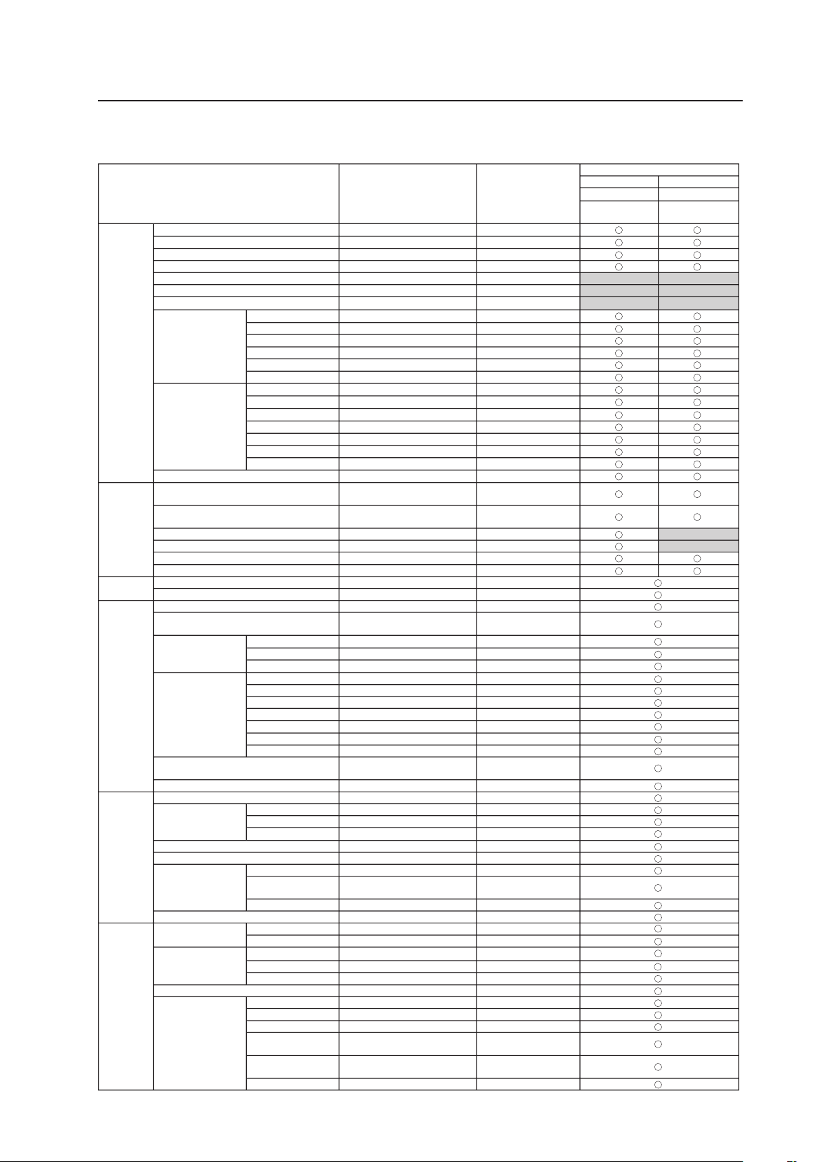
107
Before Beginning Adjustments
2) Integrator mode
7 PDP-425CMX/PDP-42MXE10
Variable range
(STEP)
Factory setting
PDP-425CMX/PDP-42MXE10
INPUT1 INPUT2
PC signal PC signal
Analog RGB Digital RGB
PICTURE CONTRAST 0 to +255 +128
BRIGHTNESS 0 to +255 +128
H.ENHANCE 0 to +15 0
V.ENHANCE 0 to +15 0
COLOR 0 to +127 +64
TINT 0 to +60 +30
SHARPNESS 0 to +15 +8
WHITE BALANCE R.HIGH 0 to +255 +128
G.HIGH 0 to +255 +128
B.HIGH 0 to +255 +128
R.LOW 0 to +255 +128
G.LOW 0 to +255 +128
B.LOW 0 to +255 +128
COLOR DETAIL RED 0 to +60 +30
YELLOW 0 to +60 +30
GREEN 0 to +60 +30
CYAN 0 to +60 +30
BLUE 0 to +60 +30
MAGENTA 0 to +60
–
+30
C.DETAIL RESET NO
GAMMA 1.8 to 2.4 2.2
SCREEN H.POSITION 0 to +255 (for PC signal)
0 to +127 (for video signal)
+128
(for PC signal)
+64
(for video signal)
V.POSITION 0 to +255 (for PC signal)
0 to +127 (for video signal)
+128
(for PC signal)
+64
(for video signal)
CLOCK 0 to +255 +128
PHASE 0 to +31 +16
H.SIZE 0 to +63 0
V.SIZE 0 to +63 0
SETUP BRT.ENHANCE OFF-ON OFF
SUB VOLUME 0 to 20 20
OPTION
(Page 1)
PROGRAM TIMER Refer to pg. 163 Refer to pg. 163
SCREEN MASK OFF-INVERSE-WHITE-RED-
GREEN-BLUE-YELLOW
OFF
SIDE MASK R.LEVEL 0 to +255 +80
G.LEVEL 0 to +255 +80
B.LEVEL 0 to +255 +80
VIDEO WALL DIVIDER 1-4-9-16-25 OFF
POSITION Refer to pg. 166 Refer to pg. 166
TYPE NORMAL-ADJUSTED NORMAL
AUTO ID ON-OFF OFF
P.ON DELAY OFF-ON-MODE1-MODE2 OFF
ABL LINK ON-OFF OFF
REPEAT TIMER Refer to pg. 169 Refer to pg. 169
BAUD RATE 9600BPS-19200BPS-38400BPS-
1200BPS-2400BPS-4800BPS
9600BPS
ID NO.SET ALL-01H to FFH ALL
OPTION
(Page 2)
FAN CONTROL AUTO-MAX AUTO
OSD DISPLAY ON-OFF ON
SIZE LARGE-SMALL LARGE
ANGLE H-V H
FRONT INDICATOR ON-OFF ON
COLOR MODE NORMAL-STUDIO NORMAL
PRO USE UNDERSCAN ON-OFF OFF
IMAGE PROCESS NORMAL-PURE-
MONO TONE-HIGH CNT
NORMAL
SIGNAL TYPE MOTION-STILL-NON-STD MOTION
FRC ON-OFF ON
OPTION
(Page 3)
PWR.ON MODE INPUT LAST-INPUT1-INPUT2-MULTI
LAST
VOLUME LAST-0-42 LAST
SEAMLESS SW SEAMLESS SW ON-OFF OFF
SELECT1 INPUT1-INPUT2
INPUT1
SELECT2 INPUT1-INPUT2
INPUT2
MIRROR MODE OFF-X-Y-XY OFF
MULTISCREEN SET S BY S SIZE NORMAL-FULL NORMAL
S BY S LAYOUT MODE 1-MODE 2-MODE 3 MODE1
PIP SIZE 1-4 2
TRANSLUCENT PIP 80%-70%-60%-50%-40%-
30%-20%-10%-OFF
OFF
BANNER PIP OFF-TOP-MID-HIGH-MID-LOW-
BOTTOM
OFF
BANNER INPUT INPUT1-INPUT2 INPUT1
(Note) The OPTION settings are common settings for all inputs.
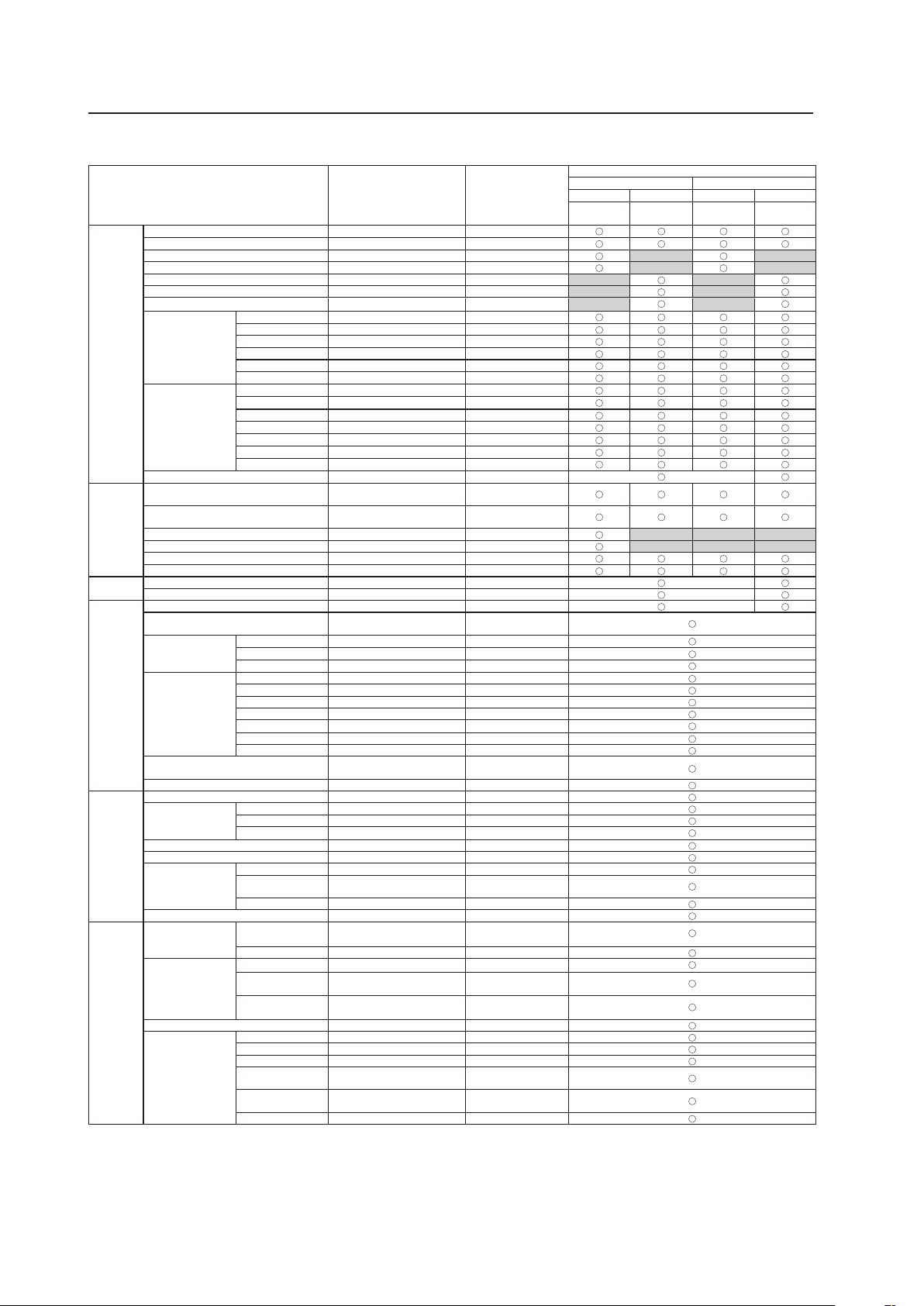
108
Before Beginning Adjustments
7 PDP-425CMX/PDP-42MXE10★
Variable range
(STEP)
Factory setting
PDP-425CMX/PDP-42MXE10
INPUT1 INPUT2
PC signal
Video signal
★
PC signal
Video signal
★
Analog RGB
Component
RGB
Digital RGB Digital HDCP
PICTURE CONTRAST 0 to +255 +128
BRIGHTNESS 0 to +255 +128
H.ENHANCE 0 to +15 0
V.ENHANCE 0 to +15 0
COLOR 0 to +127 +64
TINT 0 to +60 +30
SHARPNESS 0 to +15 +8
WHITE BALANCE R.HIGH 0 to +255 +128
G.HIGH 0 to +255 +128
B.HIGH 0 to +255 +128
R.LOW 0 to +255 +128
G.LOW 0 to +255 +128
B.LOW 0 to +255 +128
COLOR DETAIL RED 0 to +60 +30
YELLOW 0 to +60 +30
GREEN 0 to +60 +30
CYAN 0 to +60 +30
BLUE 0 to +60 +30
MAGENTA 0 to +60
–
+30
C.DETAIL RESET NO
GAMMA 1.8 to 2.4 2.2
SCREEN H.POSITION 0 to +255 (for PC signal)
0 to +127 (for video signal)
+128
(for PC signal)
+64
(for video signal)
V.POSITION 0 to +255 (for PC signal)
0 to +127 (for video signal)
+128
(for PC signal)
+64
(for video signal)
CLOCK 0 to +255 +128
PHASE 0 to +31 +16
H.SIZE 0 to +63 0
V.SIZE 0 to +63 0
SETUP BRT.ENHANCE OFF-ON OFF
SUB VOLUME 0 to 20 20
OPTION
(Page 1)
PROGRAM TIMER Refer to pg. 163 Refer to pg. 163
SCREEN MASK OFF-INVERSE-WHITE-RED-
GREEN-BLUE-YELLOW
OFF
SIDE MASK R.LEVEL 0 to +255 +80
G.LEVEL 0 to +255 +80
B.LEVEL 0 to +255 +80
VIDEO WALL DIVIDER 1-4-9-16-25 OFF
POSITION Refer to pg. 166 Refer to pg. 166
TYPE NORMAL-ADJUSTED NORMAL
AUTO ID ON-OFF OFF
P.ON DELAY OFF-ON-MODE1-MODE2 OFF
ABL LINK ON-OFF OFF
REPEAT TIMER Refer to pg. 169 Refer to pg. 169
BAUD RATE 9600BPS-19200BPS-38400BPS-
1200BPS-2400BPS-4800BPS
9600BPS
ID NO.SET ALL-01H to FFH ALL
OPTION
(Page 2)
FAN CONTROL AUTO-MAX AUTO
OSD DISPLAY ON-OFF ON
SIZE LARGE-SMALL LARGE
ANGLE H-V H
FRONT INDICATOR ON-OFF ON
COLOR MODE NORMAL-STUDIO NORMAL
PRO USE UNDERSCAN ON-OFF OFF
IMAGE PROCESS NORMAL-PURE-
MONO TONE-HIGH CNT
NORMAL
SIGNAL TYPE MOTION-STILL-NON-STD MOTION
FRC ON-OFF ON
OPTION
(Page 3)
PWR.ON MODE INPUT LAST-INPUT1-INPUT2-INPUT3-
INPUT4-INPUT5-MULTI
★
LAST
VOLUME LAST-0-42 LAST
SEAMLESS SW SEAMLESS SW ON-OFF OFF
SELECT1 INPUT1-INPUT2-INPUT3-
INPUT4-INPUT5
★
INPUT1
SELECT2 INPUT1-INPUT2-INPUT3-
INPUT4-INPUT5
★
INPUT2
MIRROR MODE OFF-X-Y-XY OFF
MULTISCREEN SET S BY S SIZE NORMAL-FULL NORMAL
S BY S LAYOUT MODE 1-MODE 2-MODE 3 MODE1
PIP SIZE 1-4 2
TRANSLUCENT PIP 80%-70%-60%-50%-40%-
30%-20%-10%-OFF
OFF
BANNER PIP OFF-TOP-MID-HIGH-MID-LOW-
BOTTOM
OFF
BANNER INPUT INPUT1-INPUT2 INPUT1
: INPUT3 to INPUT5 are applicable only when the PDA-5003 or the PDA-5004 is installed.
(Note) The OPTION settings are common settings for all inputs.
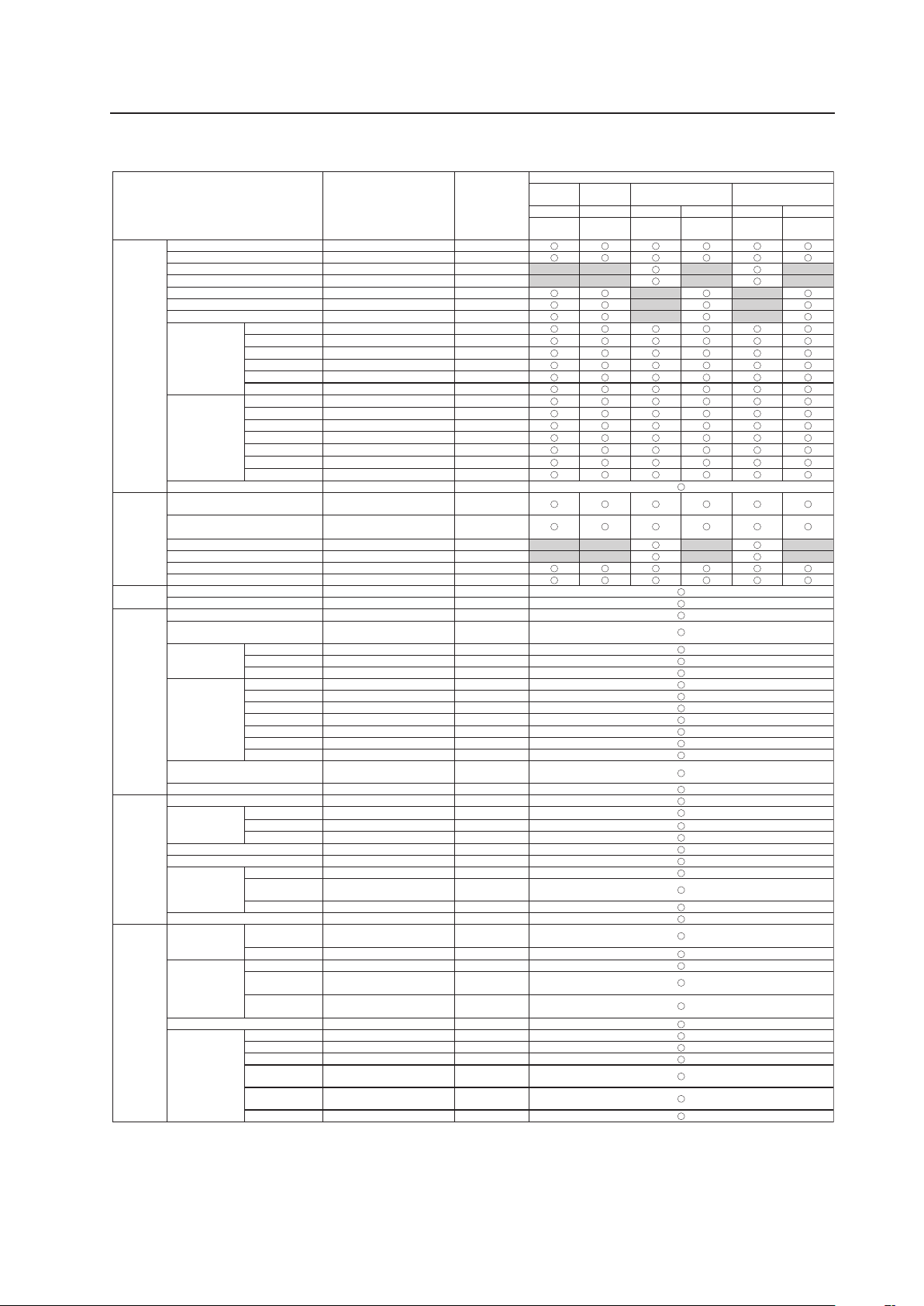
109
Before Beginning Adjustments
7 PDA-5003/PDA-5004
Variable range
(STEP)
Factory setting
PDA-5003/PDA-5004
INPUT3 INPUT4
INPUT5
(When PDA-5003 is installed)
INPUT5
(When PDA-5004 is installed)
Video signal Video signal
PC signal
Video signal
PC signal
Video signal
S video Composite
Analog
RGB
Component
RGB
Analog
RGB
Component
RGB
PICTURE CONTRAST 0 to +255 +128
BRIGHTNESS 0 to +255 +128
H.ENHANCE 0 to +15 0
V.ENHANCE 0 to +15 0
COLOR 0 to +127 +64
TINT 0 to +60 +30
SHARPNESS 0 to +15 +8
WHITE BALANCE R.HIGH 0 to +255 +128
G.HIGH 0 to +255 +128
B.HIGH 0 to +255 +128
R.LOW 0 to +255 +128
G.LOW 0 to +255 +128
B.LOW 0 to +255 +128
COLOR DETAIL RED 0 to +60 +30
YELLOW 0 to +60 +30
GREEN 0 to +60 +30
CYAN 0 to +60 +30
BLUE 0 to +60 +30
MAGENTA 0 to +60 +30
C.DETAIL RESET NO
GAMMA 1.8 to 2.4
2.2
SCREEN H.POSITION 0 to +255 (for PC signal)
0 to +127 (for video signal)
+128 (for PC signal)
+64
(for video signal)
V.POSITION 0 to +255 (for PC signal)
0 to +127 (for video signal)
+128 (for PC signal)
+64
(for video signal)
CLOCK 0 to +255 +128
PHASE 0 to +31 +16
H.SIZE 0 to +63 0
V.SIZE 0 to +63 0
SETUP BRT.ENHANCE OFF-ON OFF
SUB VOLUME 0 to 20 20
OPTION
(Page 1)
PROGRAM TIMER Refer to pg. 163 Refer to pg. 163
SCREEN MASK OFF-INVERSE-WHITE-RED-
GREEN-BLUE-YELLOW
OFF
SIDE MASK R.LEVEL 0 to +255 +80
G.LEVEL 0 to +255 +80
B.LEVEL 0 to +255 +80
VIDEO WALL DIVIDER 1-4-9-16-25 OFF
POSITION Refer to pg. 166 Refer to pg. 166
TYPE NORMAL-ADJUSTED NORMAL
AUTO ID ON-OFF OFF
P.ON DELAY OFF-ON-MODE1-MODE2 OFF
ABL LINK ON-OFF OFF
REPEAT TIMER Refer to pg. 169 Refer to pg. 169
BAUD RATE 9600BPS-19200BPS-38400BPS-
1200BPS-2400BPS-4800BPS
9600BPS
ID NO.SET ALL-01H to FFH ALL
OPTION
(Page 2)
FAN CONTROL AUTO-MAX AUTO
OSD DISPLAY ON-OFF ON
SIZE LARGE-SMALL LARGE
ANGLE H-V H
FRONT INDICATOR ON-OFF ON
COLOR MODE NORMAL-STUDIO NORMAL
PRO USE UNDERSCAN ON-OFF OFF
IMAGE PROCESS NORMAL-PURE-
MONO TONE-HIGH CNT
NORMAL
SIGNAL TYPE MOTION-STILL-NON-STD MOTION
FRC ON-OFF ON
OPTION
(Page 3)
PWR.ON MODE INPUT LAST-INPUT1-INPUT2-INPUT3-
INPUT4-INPUT5-MULTI
★
LAST
VOLUME LAST-0-42 LAST
SEAMLESS SW SEAMLESS SW ON-OFF OFF
SELECT1 INPUT1-INPUT2-INPUT3-
INPUT4-INPUT5
★
INPUT1
SELECT2 INPUT1-INPUT2-INPUT3-
INPUT4-INPUT5
★
INPUT2
MIRROR MODE OFF-X-Y-XY OFF
MULTISCREEN SET S BY S SIZE NORMAL-FULL NORMAL
S BY S LAYOUT MODE 1-MODE 2-MODE 3 MODE 1
PIP SIZE 1-4 2
TRANSLUCENT PIP 80%-70%-60%-50%-40%-
30%-20%-10%-OFF
OFF
BANNER PIP OFF-TOP-MID-HIGH-MID-
LOW-BOTTOM
OFF
BANNER INPUT INPUT1-INPUT2 INPUT1
–
: INPUT3 to INPUT5 are applicable only when the PDA-5003 or the PDA-5004 is installed.
(Note) The OPTION settings are common settings for all inputs.
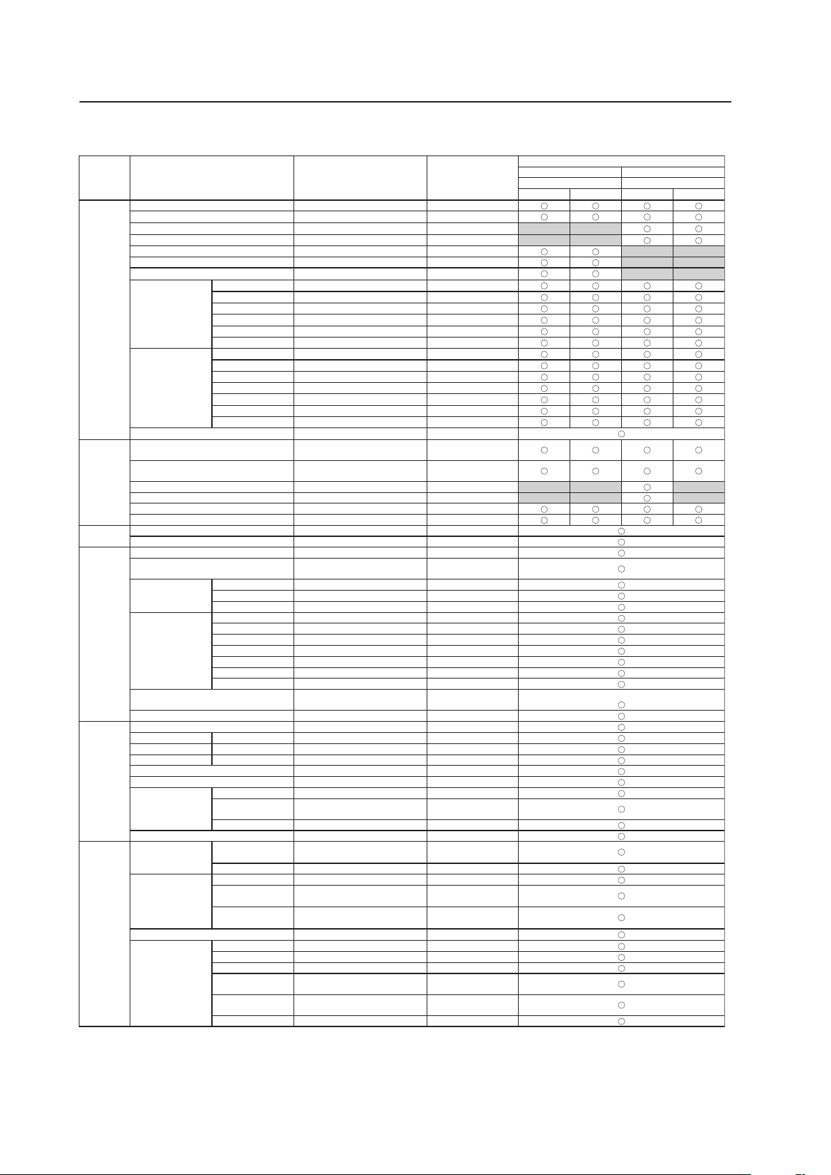
110
Before Beginning Adjustments
7 Video card other than PDA-5003/PDA-5004
Variable range
(STEP)
Factory setting
Video card other than PDA-5003/PDA-5004
INPUT3 to 5 INPUT3 to 5
Video signal PC signal
Analog Digital Analog Digital
PICTURE CONTRAST 0 to +255 +128
BRIGHTNESS 0 to +255 +128
H.ENHANCE 0 to +15 0
V.ENHANCE 0 to +15 0
COLOR 0 to +127 +64
TINT 0 to +60 +30
SHARPNESS 0 to +15 +8
WHITE BALANCE R.HIGH 0 to +255 +128
G.HIGH 0 to +255 +128
B.HIGH 0 to +255 +128
R.LOW 0 to +255 +128
G.LOW 0 to +255 +128
B.LOW 0 to +255 +128
COLOR DETAIL RED 0 to +60 +30
YELLOW 0 to +60 +30
GREEN 0 to +60 +30
CYAN 0 to +60 +30
BLUE 0 to +60 +30
MAGENTA 0 to +60 +30
C.DETAIL RESET NO
GAMMA 1.8 to 2.4 2.2
SCREEN H.POSITION 0 to +255 (for PC signal)
0 to +127 (for video signal)
+128
(for
PC signal)
+64
(for video signal)
V.POSITION 0 to +255 (for PC signal)
0 to +127 (for video signal)
+28
(for
PC signal)
+64
(for video signal)
CLOCK 0 to +255 +128
PHASE 0 to +31 +16
H.SIZE 0 to +63 0
V.SIZE 0 to +63 0
SETUP BRT.ENHANCE OFF-ON OFF
SUB VOLUME 0 to 20 20
OPTION
(Page 1)
PROGRAM TIMER Refer to pg. 163 Refer to pg. 163
SCREEN MASK OFF-INVERSE-WHITE-RED-GREEN-
BLUE-YELLOW
OFF
SIDE MASK R.LEVEL 0 to +255 +80
G.LEVEL 0 to +255 +80
B.LEVEL 0 to +255 +80
VIDEO WALL DIVIDER 1-4-9-16-25 OFF
POSITION Refer to pg. 166 Refer to pg. 166
TYPE NORMAL-ADJUSTED NORMAL
AUTO ID ON-OFF OFF
P.ON DELAY OFF-ON-MODE1-MODE2 OFF
ABL LINK ON-OFF OFF
REPEAT TIMER Refer to pg. 169 Refer to pg. 169
BAUD RATE 9600BPS-19200BPS-38400BPS-
1200BPS-2400BPS-4800BPS
9600BPS
ID NO.SET ALL-01H to FFH ALL
OPTION
(Page 2)
FAN CONTROL AUTO-MAX AUTO
OSD DISPLAY ON-OFF ON
SIZE LARGE-SMALL LARGE
ANGLE H-V H
FRONT INDICATOR ON-OFF ON
COLOR MODE NORMAL-STUDIO NORMAL
PRO USE UNDERSCAN ON-OFF OFF
IMAGE PROCESS NORMAL-PURE-
MONO TONE-HIGH CNT
NORMAL
SIGNAL TYPE MOTION-STILL-NON-STD MOTION
FRC ON-OFF ON
OPTION
(Page 3)
PWR.ON MODE INPUT LAST-INPUT1-INPUT2-INPUT3-
INPUT4-INPUT5-MULTI
★
LAST
VOLUME LAST-0-42 LAST
SEAMLESS SW SEAMLESS SW ON-OFF OFF
SELECT1 INPUT1-INPUT2-INPUT3-
INPUT4-INPUT5
★
INPUT1
SELECT2 INPUT1-INPUT2-INPUT3-
INPUT4-INPUT5
★
INPUT2
MIRROR MODE OFF-X-Y-XY OFF
MULTISCREEN SET S BY S SIZE NORMAL-FULL NORMAL
S BY S LAYOUT MODE 1-MODE 2-MODE 3 MODE 1
PIP SIZE 1-4 2
TRANSLUCENT PIP 80%-70%-60%-50%-40%-
30%-20%-10%-OFF
OFF
BANNER PIP OFF-TOP-MID-HIGH-MID-
LOW-BOTTOM
OFF
BANNER INPUT INPUT1-INPUT2 INPUT1
-
: INPUT3 to INPUT5 are applicable only when the PDA-5003 or the PDA-5004 is installed.
(Note) The OPTION settings are common settings for all inputs.
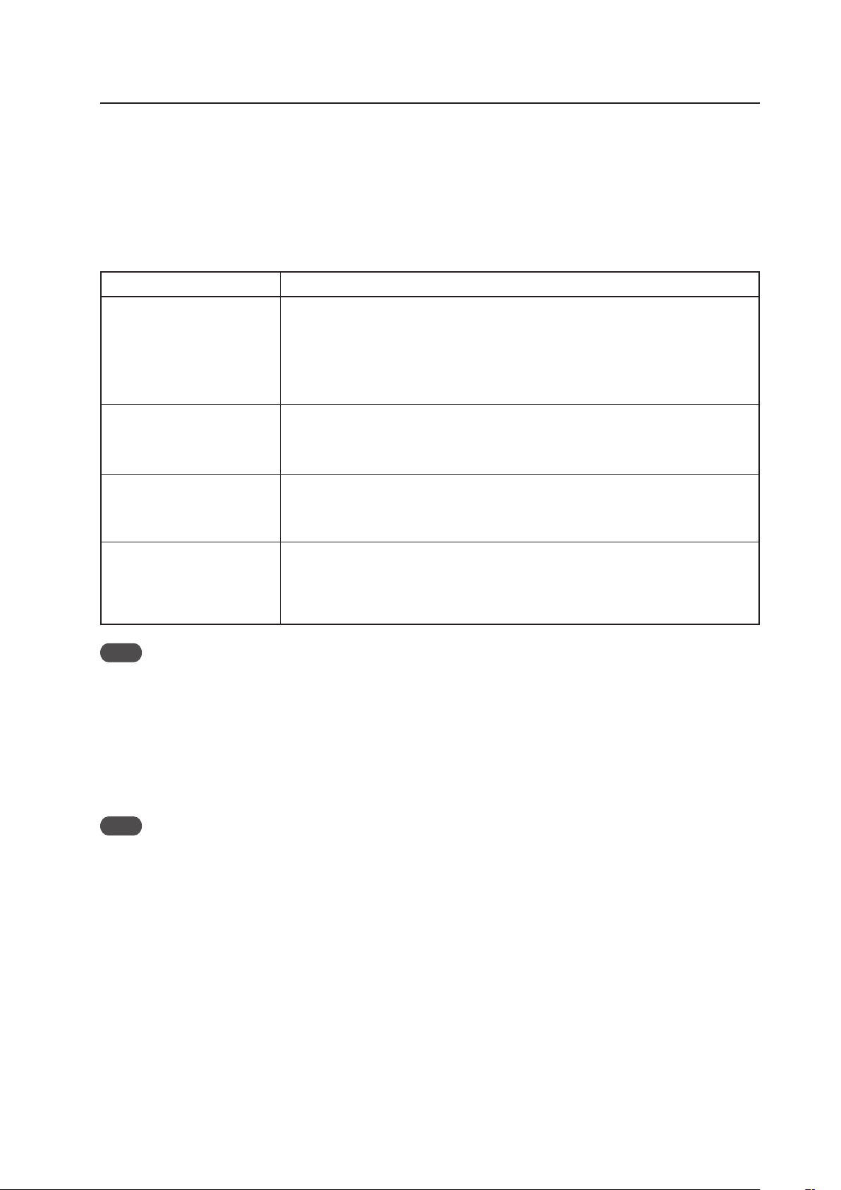
111
Operation in the normal-
operation mode
• Power ON/OFF
• Switching input
• Switching screen size
• Volume adjustment
• FUNCTIONAL LOCK setting
Adjustments and settings in the
menu mode
Adjustments and settings in the
integrator mode
Adjustments and settings in the
RS-232C adjustment
• 3 seconds after an operation
• When the standby mode is designated by a remote-control, main-control panel or <POF>
command
• When the format of the displayed signal changes
(NOTE) Of the RS-232C commands that can be used in the normal-operation mode, there are
some that cannot be saved in the last memory when using the normal-operation mode.
For details, refer to section 5.5, “RS-232C Adjustment (pg. 193)”.
• 3 seconds after an operation
• When the standby mode is designated by a remote-control, main-control panel or <POF>
command
• When the format of the displayed signal changes
• 3 seconds after an operation
• When the standby mode is designated by a remote-control, main-control panel or <POF>
command
• When the format of the displayed signal changes
• 3 seconds after a command is sent, or when the next command is sent within 4 seconds
• When the standby mode is designated by a remote-control, main-control panel or <POF>
command
• When an adjustment or setting is changed using a command
• When the format of the displayed signal changes
Item
Saving to Memory
Note
If the system is started or stopped by turned ON/OFF from a circuit breaker, use the system only after first saving
adjustments and settings in the last memory according to the timing described above. Also, with this operating method,
count errors may occur in the hour meter.
5.1.6 Aging
After the power has been turned ON, input a white 100% signal to age thus stabilize the unit (about 30 minutes). When
adjustments are made after aging is performed, it possible to perform more precise adjustments.
Note
When a still screen is displayed for a long period, the image may possibly be burned in to the screen.
5.1.5 Last Memory
The timing for the last memory is listed below.
When one of the following operations is performed before the timing is complete, the last memory function may not
perform.
• MAIN POWER switch is turned OFF
• Power cord is removed from the power outlet
• The breaker to the power outlet is turned OFF
Before Beginning Adjustments
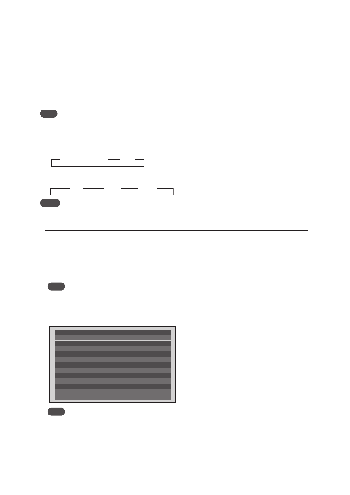
112
Normal Operating Mode
5.2 Normal Operation Mode
5.2.1 About normal operation mode
The following controls are possible in the normal operation mode.
1 Switching input
• Pressing the [INPUT1] to [INPUT5] buttons on the remote control changes the input that setting.
• Pressing the [INPUT] button on the main-control panel changes the input each time the button is pressed.
Note
When a PDA-5003 or a PDA-5004 is not installed, the input switches only between INPUT1 and INPUT2.
2 Switching the screen size
• Each time the [SCREEN SIZE] button on the remote control or main-control panel is pressed, the display screen
size changes.
When reproducing a PC signal
When reproducing a video signal (signal other than a PC signal) ★ (Applicable only when a PDA-5003 or a PDA-
5004 is installed.)
Notes
• The reproducible screen size changes according to the input signal.
Refer to the section 5.1.3, “List of Input Correspondence Signals” (pg. 94).
• To select ‘Underscan’, set the PRO USE option in the integrator mode.
When this display is to be used for commercial use or for public viewing, such as in a coffee shop or hotel,
reducing or enlarging the screen by using the screen-size-switching function could infringe on the copyright of
the creator according to copyright laws.
2 Display call
A Pressing the [DISPLAY] button on the remote control or main-control panel displays the current input function,
horizontal and vertical frequency of the input signal, the type of signal, and the screen size (DISPLAY CALL 1).
Note
The displayed horizontal and vertical frequencies are measured values. Measurement errors are possible.
B Pressing the [DISPLAY] button on the remote control or main-control panel again for 3 seconds or more when the
display described in A above is displayed, cause various settings and internal temperature to be displayed as
shown below (DISPLAY CALL 2).
3 3 4:3
ZOOM 2
2.35:1 2
3
FULL
14:9 2
WIDE
3 3
DOT BY DOT/FULL 4: 3
T E M P E R AT U R E
H O U R M E T E R
O S D
BAU D R AT E
I N F O R M AT I O N
: A B C D E F G H I J K L M N
FA N C O N T R O L
I D N O. S E T
C O L O R M O D E
: + 2 5
: AU TO
: 9 6 0 0 B P S
: O N
: A L L
: N O R M A L
: 0 0 2 3 9 H
DAT E
: 0 0 1 A 0 0 1 X
L O T
: 0 0 1 A 0 0 1 K
S E R I A L N O.
: * * * * * * * * * * * * * * * *
P D P - 4 2 5 C M X / LV C 5
Note
When the displayed temperature is high, the panel shuts down. However, the display itself should always be
used as an indicator.
SERIAL NO.: Displays the serial number of the product
LOT/DATE: Displays the manufacturing control number
HOUR METER: Displays the conduction time for the product
TEMPERATURE: Displays the outside air temperature that is
measured by a temperature sensor located in
the product
Other items: Displays the settings in the integrator mode

113
Normal Operating Mode
4 Volume Adjustment/Muting
• Pressing the [VOLUME+] button on the remote control or main-control panel raises the volume.
• Pressing the [VOLUME-] button on the remote control or main-control panel lowers the volume.
• Pressing the [MUTING] button on the remote control switches between no sound (muting ON) and sound (muting
OFF) each time the button is pressed.
Note
Muting is cleared when the power is turn OFF.
5 Auto screen adjustment
• Pressing the [AUTO SET UP] button on the remote control or main-control panel during PC signal input causes the
‘SCREEN’ in the menu mode to adjust automatically. If a multi screen is being used, only the main screen can be
adjusted.
Notes
• Adjustment cannot be performed from INPUT2.
• Adjustment cannot be performed well when the input signal is a low brightness signal such as black, or is showing
movement.
• Automatic SCREEN adjustment values are reflected under ‘SCREEN’ in the menu mode.
6 Point Zoom (only when using the remote control)
• Pressing the [POINT ZOOM] button on the remote control designates the POINT ZOOM screen. Each time the
button is pressed, the magnification rate changes as shown below.
• During magnification, it is possible to scroll the display position using the [5/∞/2/3] buttons on the remote
control.
7 Multi screen (only when using the remote control)
• Pressing the [SPLIT] button on the remote control designates a multi screen. Each time the button is pressed, the
screen changes as shown below.
• When input is switched during a multi-screen display, input of the main screen is switched.
• When the [SUB INPUT] button on the remote control is pressed during a multi-screen display, the input of the sub
screen is switched.
• When the [SWAP] button on the remote control is pressed during a multi-screen display, the main screen and sub
screen are switched.
• Press the [2/3] buttons on the remote control during multi-screen mode to change the sound on the main screen
and the subscreen. This overrides last memory.
• When the [PIP SHIFT] button on the remote control is pressed during a PinP screen display, the display position of
the sub screen changes as shown below.
8 Some other RS-232C commands besides those described above are also effective.
For details, refer to section 5.5, “RS-232C Adjustment” (pg. 193).
Notes
• Same function display is possible for main input and sub input. However, during circuit processing, since the high-
image quality circuit is used for the main input, the screen looks different on the sub screen.
• While the video wall is set, multi-screen display is unavailable.
• When the video wall is set or during multi-screen display, point zoom is unavailable.
3
Lower right 3
Upper right
Lower left 2 Upper left 2
3
LEVEL1 3
LEVEL2
LEVEL4 2 LEVEL3 2
3
Side-by-side
Picture-in-picture 2OFF 2
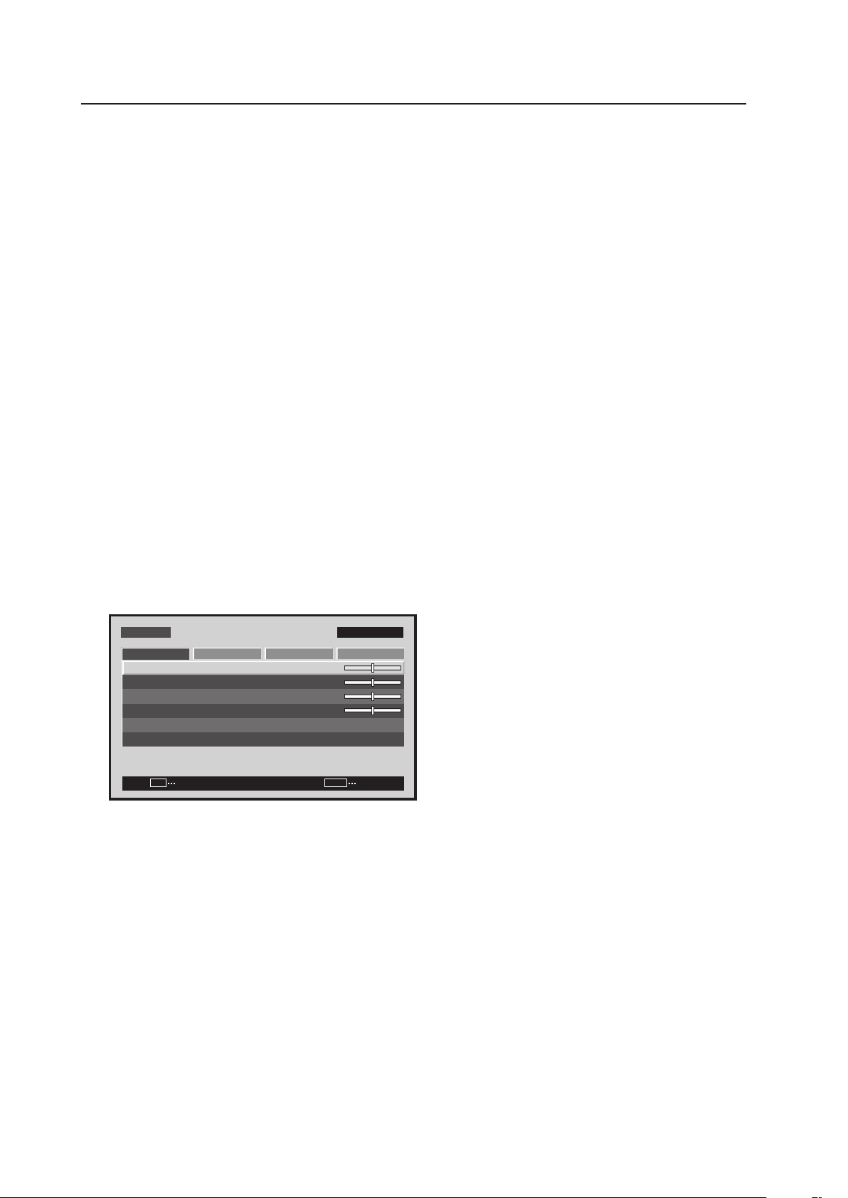
114
Menu Mode
5.3 Menu Mode
5.3.1 About menu mode
1) Entering/leaving the menu mode
• Pressing the [MENU] button on the remote control or main-control panel in the normal-operation mode causes the
menu screen to appear.
Pressing the [MENU] button while in the menu mode causes the menu to close.
2) When performing adjustment in the menu mode...
• The signal and screen adjustment values are saved in memory for each input function and input signal. For details,
refer to section 5.4.4, “PICTURE, White Balance and SCREEN Position Adjustment Values Memory Area Tables”
(pg. 188).
3) Precautions
(1) In the following cases, the menu closes automatically:
• Input is switched
• No operation for approximately 3 minutes
(2) For details about menu adjustments, refer to the Operating Instructions.
(3) It is recommended that adjustment and settings be performed with signal that will actually be input.
(4) The items that can be adjusted and set differ according to the input signal. Also, changing settings is only
possible when no video signal is input.
5.3.2 Concerning the display of the OSD of each item
Example of Menu Display:
S C R E E N SET U P O P T I O N
:
0
:
0
:
0
C O N T R A S T
:
0
B R I G H T N E S S
H . E N H A N C E
V. E N H A N C E
P I C T U R E R E S E T
P I C T U R E
M E N U I N P U T 1
ENTER
SET
EXIT
MENU
Images shown here may differ from the actual display image.
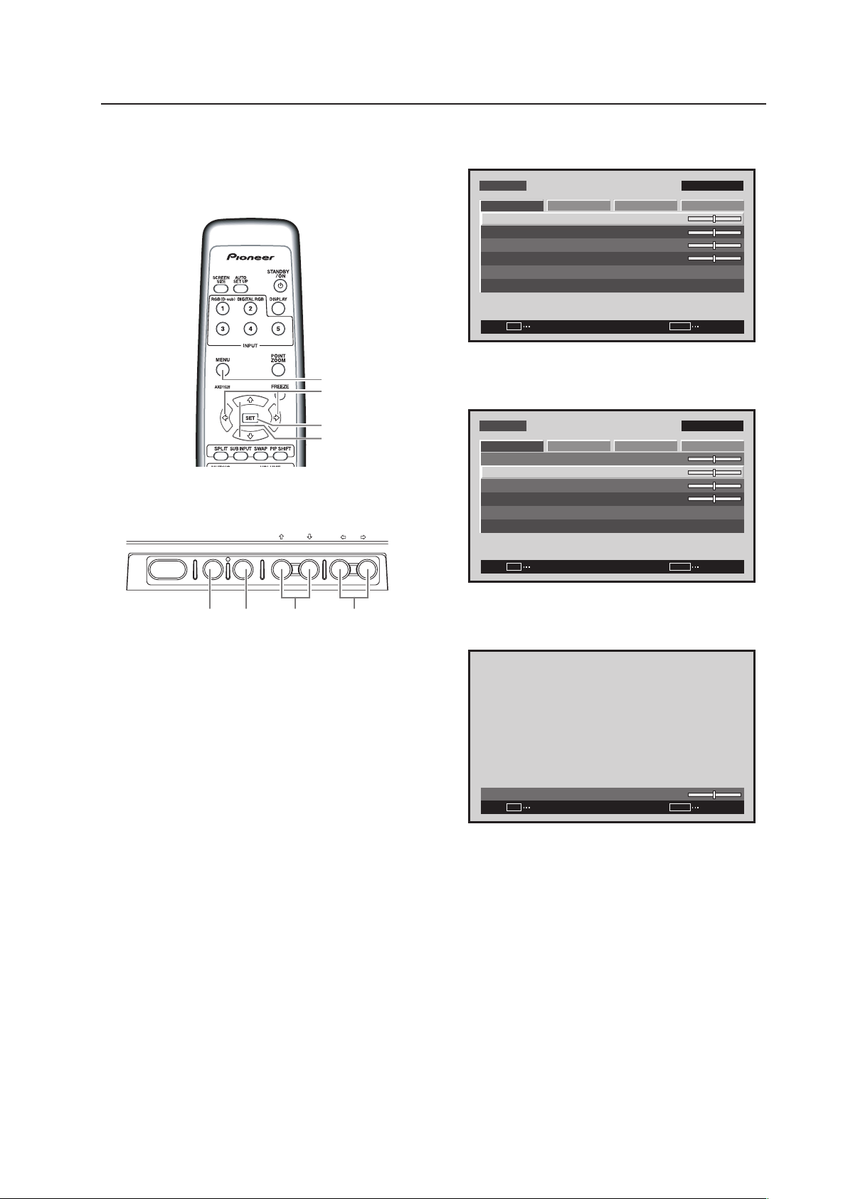
115
Menu Mode
5.3.3 Example of a Menu Mode Operation
The basic operation in the menu mode will be explained
using brightness adjustment as an example.
1 Press the MENU button to display the menu
screen.
S C R E E N S E T U P O P T I O N
:
0
:
0
:
0
C O N T R A S T
:
0
B R I G H T N E S S
H . E N H A N C E
V. E N H A N C E
P I C T U R E R E S E T
P I C T U R E
M E N U INPU T 1
ENTER
SET
EXIT
MENU
2 Use the 5/∞ buttons to select the adjustment
item then press the SET button.
S C R E E N S E T U P O P T I O N
:
0
:
0
:
0
C O N T R A S T
:
0
B R I G H T N E S S
H . E N H A N C E
V. E N H A N C E
P I C T U R E R E S E T
P I C T U R E
M E N U INPU T 1
ENTER
SET
EXIT
MENU
3 Use the 2/3 buttons to adjust the picture
quality as desired.
:
0
B R I G H T N E S S
SET
SET
EXIT
MENU
It is possible to move to other adjustment items
with the 5/∞ buttons.
4 Press the SET button.
Pressing the SET button writes the value into
memory and returns the display to the step 2
screen.
5 When the setup is finished, press the MENU
button to exit the menu screen.
MENU
5/∞
SET
2/3
Remote control unit
STANDBY/ON MENU
DISPLAY
/ SET
– VOL +INPUT SCREEN SIZE
�
2/3MENU SET 5/∞
Main-control panel
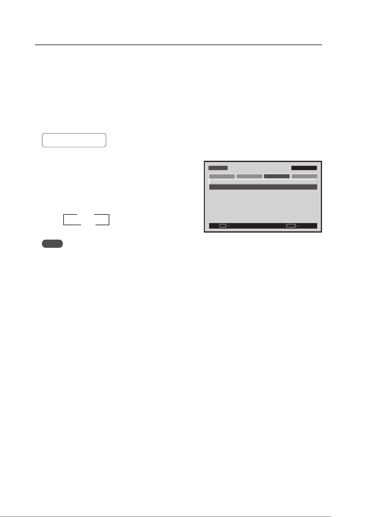
116
Menu Mode
5.3.4 Adjustment and setting in the Menu Mode
1) Power Management Setting
When no video signal (synchronizing signal) is detected, this function automatically sets the energy saving state to
save power.
• To disable the energy saving function, set to [OFF].
• When there is PC signal input:
To switch between the normal-operation state and the energy saving state is depended upon the presence of an
input signal, set ‘POWER MANAGEMENT’ to [ON].
Factory setting: OFF
Notes
• To return from the power standby state to the normal operation state, press the power button on the remote
control or the main control panel.
• To return from the energy saving state (by power management) to the normal operation state, operate the PC or
press the [INPUT] button on the remote control or main-control panel.
However, during SYNC ON G or composite SYNC input, operation does not return by simply operating the personal
computer. After operating the personal computer, press the [INPUT] button.
• The power consumption during power standby.
PDP-425CMX: 1.2 W
PDP-42MXE10: 1.5 W
1 Select ‘SETUP‘.
2 Place the cursor over ‘POWER MANAGEMENT’ and
change the setting with the [SET] button.
Each time the [SET] button is pressed, the setting is
changed as shown below.
M E N U IN P U T 1
CHANGE
SET
EXIT
MENU
S C R E E N S E T U P OPTI O N
P O W E R M G T. : O F F
S I G N A L F O R M AT
P I C T U R E
3 OFF
ON 2
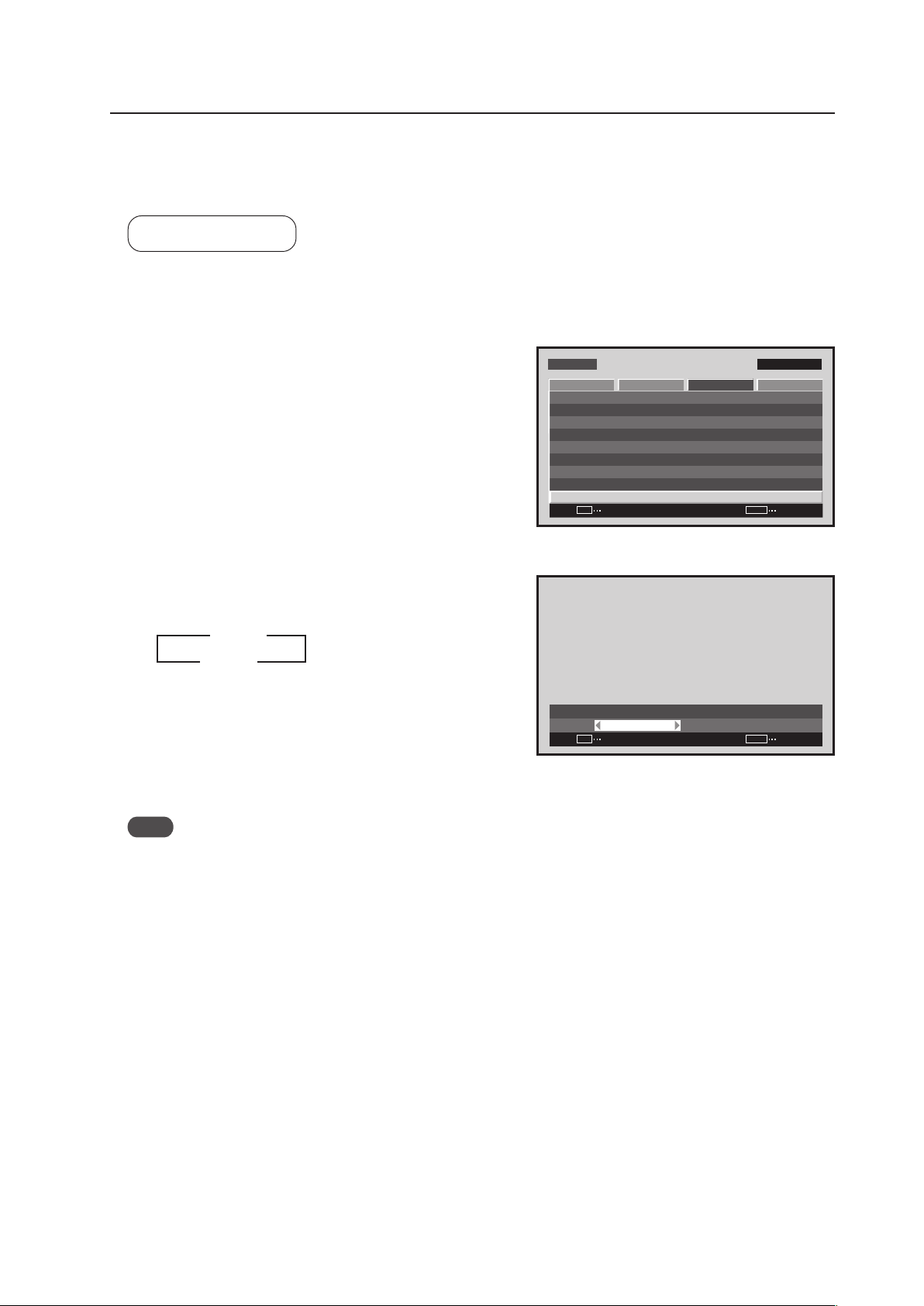
117
Menu Mode
2) Signal Format Setting
This display automatically identifies PC signals and video signals such as from a DVD player by the frequency of the
input signal. The panel is equipped with a function for identifying the resolution of a PC signal.
Factory setting: AUTO
1 Select ‘SETUP’.
2 Place the cursor over ‘SIGNAL FORMAT’ then press the
[SET] button.
3 Press the [2/3] buttons to change the setting.
Each time a [2/3] button is pressed, the signal format
changes as shown below.
• AUTO ........ It is distinguished as in “5.1.3 List of
Input Correspondence Signals 2) Input
correspondence signals personal
computer signals” (pages 95 to 97)
• Others ....... Selectable resolutions are displayed
Note
The display method and selectable screen size differs for each setting. In order to obtain a proper reproduction
method and screen size, check the signal format setting when the signal is input then change the setting as necessary.
M E N U IN P U T 1
ENTER
SET
EXIT
MENU
S C R E E N S E T U P O P T I O N
: D I S A B L E
: M I D D L E
C O L O R T E M P. : M I D D L E
AU T O P OW E R O F F
D N R
: L O W
: O N
M P E G N R
C T I
: O F F
: R G B
P U R E C I N E M A
C O L O R D E C O D I N G
: A U T OC O L O R S Y S T E M
S I G N A L F O R M AT
P I C T U R E
Screen 2
:
S I G N A L F O R M AT
A U T O
SET
SET
EXIT
MENU
Screen 3
3 AUTO
Others 2
2
3

118
Menu Mode
3) Menu Language Display Setting
The factory setting for the menu display language is English. To change to another language, set the selection in the
menu.
Factory setting: ENGLISH
1 Select ‘OPTION’.
2 Place the cursor over ‘LANGUAGE’ and press the [SET]
button.
3 Each time a [2/3] button is pressed, the language
changes as shown below.
With the desired language displayed, press the [SET]
button.
Note
Setting the display language for either INPUT1 or INPUT2 sets the language for both inputs.
:
L A N G U A G E E N G L I S H
SET
SET
EXIT
MENU
Screen 3
3
ENGLISH
2 3
ESPAÑOL
2
3
DEUTSCH
2
3
3
FRANÇAIS
2
3
2
ITALIANO
2
Screen 2
:
LA N G UAG E F R A NÇA I S
SET
SET
EXIT
MENU
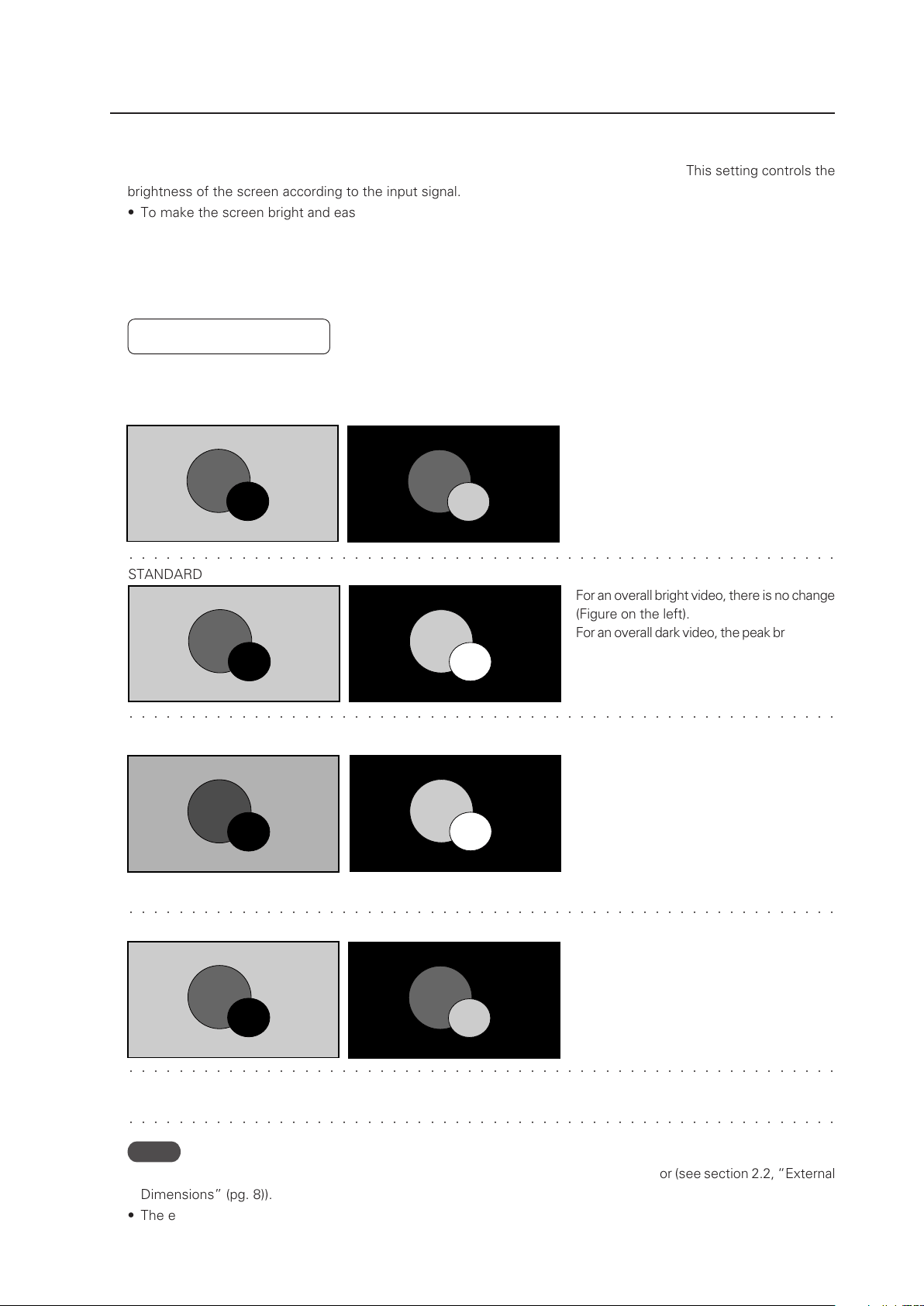
119
Menu Mode
� � � � � � � � � � � � � � � � � � � � � � � � � � � � � � � � � � � � � � � � � � � � � � � � � � � � � � � � �
� � � � � � � � � � � � � � � � � � � � � � � � � � � � � � � � � � � � � � � � � � � � � � � � � � � � � � � � �
STANDARD
For an overall bright video, there is no change
(Figure on the left).
For an overall dark video, the peak brightness
is reproduced even brighter (Figure on the
right).
MODE1, MODE2
MODE3
Power consumption is lowered by reducing
the brightness of an overall bight video
(Figure on the left).
Similar to in the STANDARD setting, an overall
dark video is peak brightness is reproduced
even brighter (Figure on the right).
The peak brightness in MODE2 is decreased
by a set amount with respect to that in
MODE1, however it is reproduced brighter
than in MODE3.
Input signal graduation is not controlled but
reproduced accurately. Deterioration of the
panel due to burning is reduced since the
peak brightness of an overall dark video is
not increased.
� � � � � � � � � � � � � � � � � � � � � � � � � � � � � � � � � � � � � � � � � � � � � � � � � � � � � � � � �
� � � � � � � � � � � � � � � � � � � � � � � � � � � � � � � � � � � � � � � � � � � � � � � � � � � � � � � � �
4) Energy Saving Setting
This is a function that reduces power consumption and reduces deterioration of the panel. This setting controls the
brightness of the screen according to the input signal.
• To make the screen bright and easy to see: Set ‘ENERGY SAVE: STANDARD’.
• To reduce power consumption: Set ‘ENERGY SAVE: MODE1, MODE2’.
• To reduce deterioration of the panel such as burning: Set ‘ENERGY SAVE: MODE 3’.
• To control according to the brightness of the room and to adjust the screen according to the surroundings: Set
‘ENERGY SAVE: AUTO’.
Factory setting: STANDARD
Differences in video reproduction by energy saving settings (illustration)
For this kind of input signal
� � � � � � � � � � � � � � � � � � � � � � � � � � � � � � � � � � � � � � � � � � � � � � � � � � � � � � � � �
AUTO The brightness is automatically changed within the STANDARD (bright) to MODE2 (dark) range according
to the brightness of the room.
Notes
• When AUTO is set, do not place objects near or let light shine directly on external sensor (see section 2.2, “External
Dimensions” (pg. 8)).
• The external sensor changes in stages; from an external light of 200 lux (rough value) to external light of 0 lux.
(As a standard)
When the white window is displayed, the
peak brightness is decreased as shown
below.
• MODE1: Decreased about 50%
• MODE2: Decreased about 60%
• MODE3: Decreased about 75%
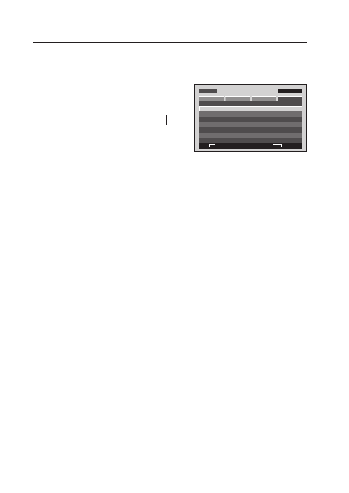
120
Menu Mode
1 Select ‘OPTION’.
2 Place the cursor over ‘ENERGY SAVE’ then press the [SET]
button to change the setting.
Each time the [SET] button is pressed, the setting changes
as shown below.
The ‘ENERGY SAVE’ setting is common for all inputs.
MENU INPUT1
CHANGE
SET
EXIT
MENU
SCREEN SETUP OPTION
LA N G U AGE
EN E R G Y S AV E
TI M E R SE T T I NG
SC R E E N M G T.
SP L I T FR E E Z E
AU TO S E T UP MOD E
AU TO F U N CTI O N
PI P D E T E CT
PICTURE
:S TAN DAR D
:I N A C TIV E
:O F F
:A C T I VE
:E N G L ISH
:O F F
Screen 2
3 STANDARD
MODE2 2 MODE1 2
3 AUTO
MODE3 2
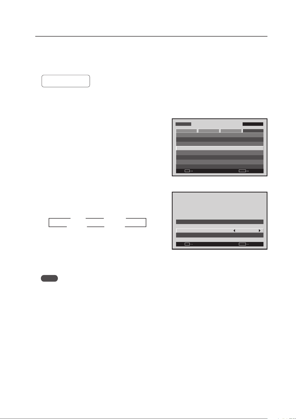
121
Menu Mode
5) Orbiter Setting
This function gradually moves the display position of the screen periodically screen position is moved at random,
horizontally or vertically).
Setting ‘MODE1’ to ‘MODE3’ is effective in reducing screen burn when a still image is displayed.
Factory setting: OFF
1 Select ‘OPTION’.
2 Select ‘SCREEN MGT.’.
2 Place the cursor on ‘ORBITER’ then press the [2/3]
buttons to change the settings.
Each time a [2/3] button is pressed, the setting changes
as shown below.
MODE1 ....... The size is reduced so the picture is
completely in the display area.
MODE2 ....... The size is increased so there are no black
bands in the display area.
MODE3 ....... It is displayed at the same size.
Notes
• When ‘MODE1’ or ‘MODE2’ has been set, it moves smoothly.
• In ‘MODE3’, it moves in dot increments. The entire screen moves 1 dot horizontally or vertically approximately
every minute. The maximum movement is 4 dots.
• When it is set to ‘OFF’, the orbiter of the PIP subscreen is still ON.
The ‘ORBITER’ setting is common for all inputs.
Screen 2
MENU INPUT1
ENTER
SET
EXIT
MENU
SCREEN SETUP OPTION
LA N G U AGE
EN E R G Y S AV E
TI M E R SE T T I NG
SC R E E N M G T.
SP L I T FR E E Z E
AU TO S E T UP MOD E
AU TO F U N CTI O N
PI P D E T E CT
PICTURE
:S TAN DAR D
:I N A C TIV E
:O F F
:A C T I VE
:E N G L ISH
:O F F
Screen 3
SET
SET
EXIT
MENU
SC R E E N M A N AGE M E NT
OR B I T ER
SO F T FOC U S
: O F F
: O F F
3 OFF
MODE3 2
2
MODE2 2
3
3
3
MODE1
2

122
Menu Mode
6) Soft Focus Setting
Images are softened by suppressing the edge contrast.
Factory setting: OFF
1 Select ‘OPTION’.
2 Select ‘SCREEN MGT.’.
2 Place the cursor on ‘SOFT FOCUS’ then press the [2/3]
buttons to change the settings.
Each time a [2/3] button is pressed, the setting changes
as shown below.
The ‘SOFT FOCUS’ setting is common for all inputs.
Screen 2
MENU INPUT1
ENTER
SET
EXIT
MENU
SCREEN SETUP OPTION
LA N G U AGE
EN E R G Y S AV E
TI M E R SE T T I NG
SC R E E N M G T.
SP L I T FR E E Z E
AU TO S E T UP MOD E
AU TO F U N CTI O N
PI P D E T E CT
PICTURE
:S TAN DAR D
:I N A C TIV E
:O F F
:A C T I VE
:E N G L ISH
:O F F
Screen 3
SET
SET
EXIT
MENU
SC R E E N M A N AGE M E NT
OR B I T ER
SO F T FOC U S
: O F F
: O F F
3 OFF
4 2
3 1
3 2
2
2 2
2
3 3 3
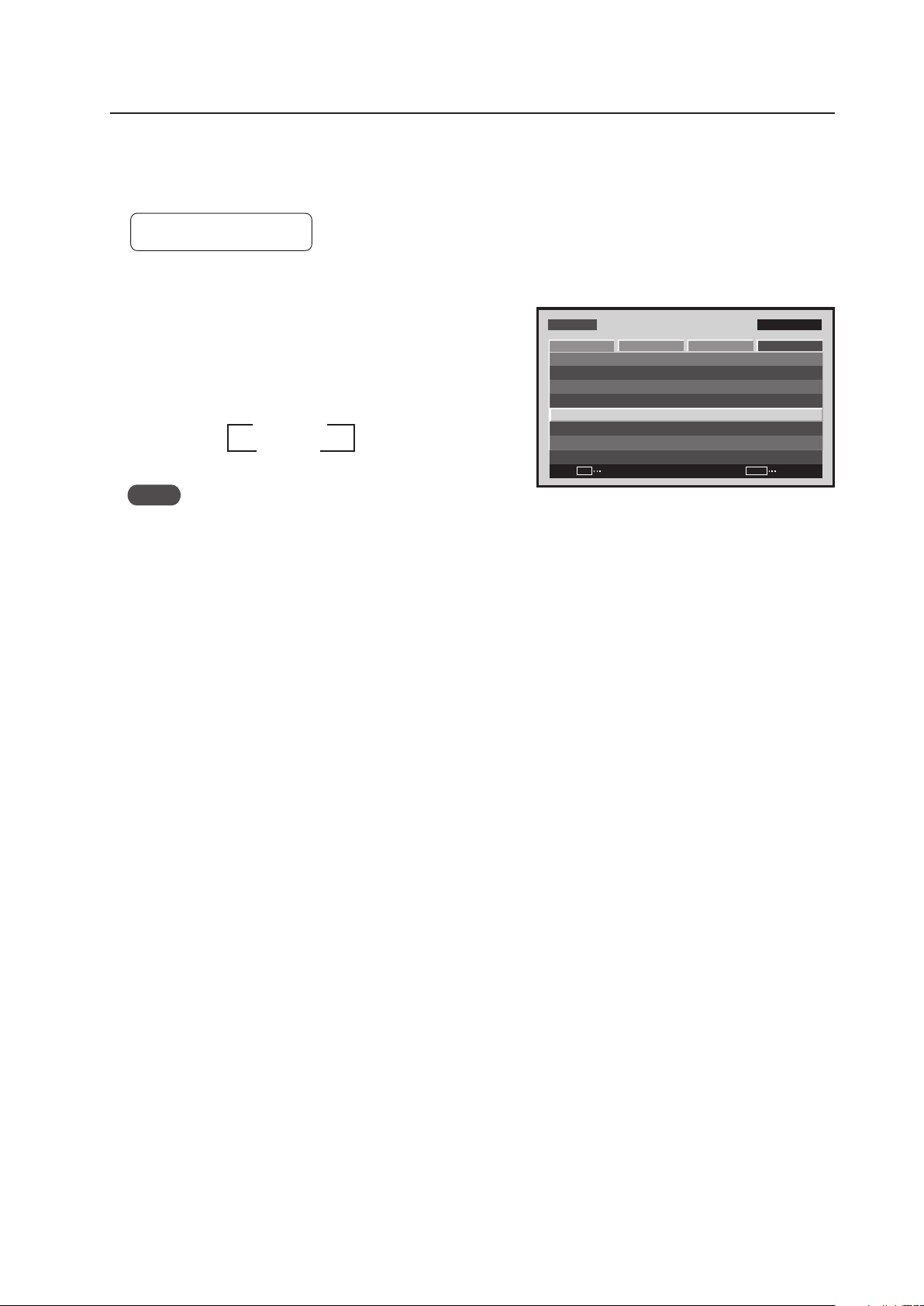
123
Menu Mode
7) Auto Set Up Mode Setting
This function automatically adjusts the signal when the power is turned ON, when the input is changed, and when
the type of input signal is changed.
Factory setting: INACTIVE
1 Select ‘OPTION’.
2 Place the cursor on ‘AUTO SET UP MODE’ then press
the [SET] button to change the setting.
Each time the [SET] button is pressed, the setting changes
as shown below.
Notes
• Items 1 and 3 are adjusted automatically.
‘SCREEN’ Adjustment inside the menu: 1. ‘POSITION’
2. ‘CLOCK’
3. ‘PHASE’
• The adjustment items are the same as when the ‘AUTO SET UP’ button is pressed on the remote control; however,
precision may be a little inferior. This difference in precision is due to short processing time in the menu settings
AUTO SET UP MODE.
• It may not be possible to precisely adjust an input signal such as when the signal has low brightness. Set the
AUTO SET UP MODE to INACTIVE, and make adjustments as explained in the following section, ‘SCREEN, CLOCK,
PHASE’.
• When the AUTO SET UP MODE is set to ACTIVE and ‘SCREEN’ is manually adjusted, ‘AUTO SET UP MODE:
ACTIVE’ is displayed.
This is to warn you that although adjustment is manual, when the input changes or when the type of signal changes
on the outside, the AUTO SET UP MODE functions and the adjusted values will be written over.
MENU INPUT1
CHANGE
SET
EXIT
MENU
SCREEN SETUP OPTION
LA N G U AGE
EN E R G Y S AV E
TI M E R SE T T I NG
SC R E E N M G T.
SP L I T FR E E Z E
AU TO S E T UP MOD E
AU TO F U N CTI O N
PI P D E T E CT
PICTURE
:S TAN DAR D
:I N A C TIV E
:O F F
:A C T I VE
:E N G L ISH
:O F F
Screen 2
3 INACTIVE
ACTIVE 2
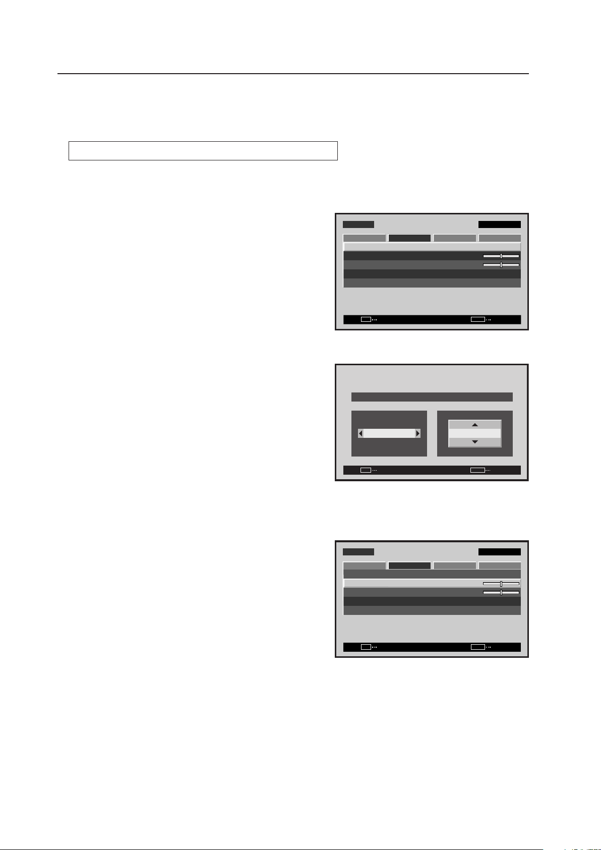
124
Menu Mode
8) Screen Position, Clock Frequency and Clock Phase Adjustment
In AUTO SET UP, the position and clock are optimally set. However, depending on the type of signal, adjustment
may be off. If this should occur, refer to the procedure below and make the adjustment manually.
Example) When a PC signal is input to INPUT1 (1024 x 768)
1 Set the screen size to ‘DOT BY DOT’.
2 Select ‘SCREEN’.
3 Place the cursor on ‘POSITION’ then press the [SET]
button.
4 Use the [5/∞] and [2/3] buttons to adjust the screen
position.
Here, the top and left side of the video display are properly
set.
1. With the [∞] button, lower the display until the mask
(black portion) protrudes into the top of the image.
2. With the [5] button, move the display to the point
where the mask at the top disappears.
3. With the [3] button, move the display until the mask
(black portion) protrudes into the right side of the image.
4. With the [2] button, move the display to the point
where the mask on the left side disappears.
5 Place the cursor on ‘CLOCK’ then press the [SET] button.
M E N U IN P U T 1
ENTER
SET
EXIT
MENU
S C R E E N S E T U P OPTI O N
:
0
:
0
P O S I T I O N
:
0 / 0
C L O C K
P H A S E
S C R E E N R E S E T
P I C T U R E
Screen 2
Screen 4
SET
SET
EXIT
MENU
P O S I T I O N
H V
+ 8 8+ 8 8
Screen 5
M E N U IN P U T 1
ENTER
SET
EXIT
MENU
S C R E E N S E T U P OPTI O N
:
:
0
P O S I T I O N
:
0 / 0
C L O C K
P H A S E
S C R E E N R E S E T
P I C T U R E
0

125
Menu Mode
6 Use the [2/3] buttons to adjust the click frequency.
In step 4, the left side was aligned while here the right
side is aligned.
1. With the [3] button, move the display until the mask
(black portion) protrudes into the right side of the image.
2. With the [2] button, move the display to the point
where the mask on the right side disappears.
7 In the adjustment in steps 5 and 6, the left side of the screen moves. With ‘POSITION’, accurately adjust the left
side of the video display again.
As in step 4, used the [2/3] buttons to align the left side.
8 In the adjustment in step 7, the right side of the screen moves. With ‘CLOCK’, adjust the right side again.
As in step 6, use the [2/3] buttons to align the left side.
Repeat steps 7 and 8 until the adjustment value converges, then adjust the ‘PHASE’.
There are vertical lines so it is easier to adjust the screen if a signal having edges is input.
9 Place the cursor on ‘PHASE’ then press the [SET] button.
0 Using the [2/3] buttons adjust the clock phase.
Move the vertical edge of the image to the point where it becomes bold.
Adjustment is now complete.
:
0
C L O C K
SET
SET
EXIT
MENU
Screen 6
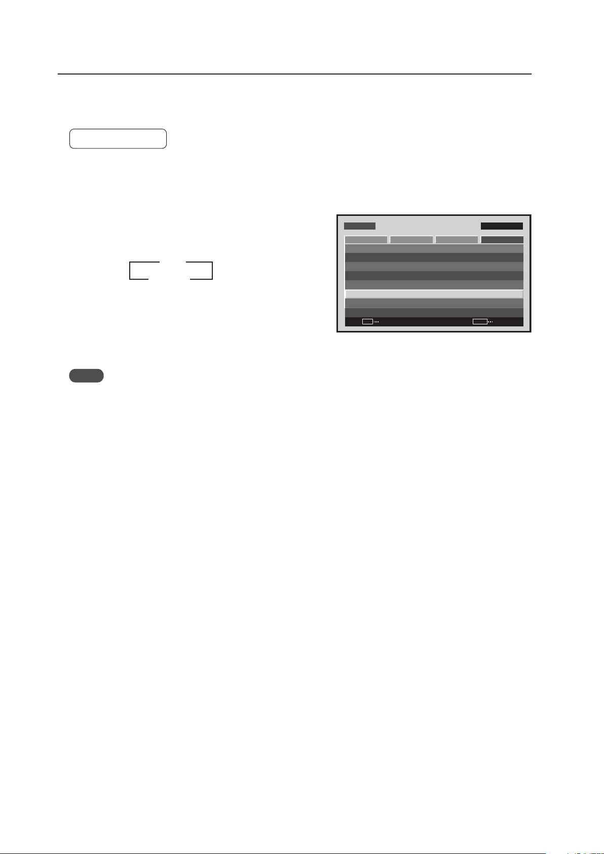
126
Menu Mode
9) Auto Function Mode Setting
With the Auto Function mode it is possible to automatically change the input when a signal is detected.
Factory setting: OFF
1 Select ‘OPTION’.
2 Place the cursor over ‘AUTO FUNCTION’ then press the
[SET] button to change the setting.
Each time the [SET] button is pressed, the setting changes
as shown below.
• When INPUT1 is selected, this function automatically
switches to that input when the signal is detected. Also,
in the Auto Function mode, after the input switches and
the signal input stops, the Auto Function returns to the
input that was used before the switch.
Notes
• The Auto Function mode is unavailable when ‘OFF’ is selected.
• When SYNC ON G or a component signal is input to INPUT1, the Auto Function is unavailable does not function.
• After the input has been switched in the Auto Function mode, press the [INPUT] button and select a different
input. The Auto Function mode activates when it detects a change in the selected input signal (from a no-input
state to an input state).
• When the power is turned OFF/ON, the Auto Function mode activates when the signal is input to the selected
input.
• The Auto Function mode is unavailable when the Menu displays, during POINT ZOOM, or during multi-screen
display.
• When the Auto Function mode is set to ‘INPUT1’ or ‘INPUT4’, ‘AUTO’ appears under the option that displays the
selected input (INPUT1 to INPUT5).
Screen 2
M E N U IN P U T 1
CHANGE
SET
EXIT
MENU
S C R E E N S E T U P OPTI O N
L A N G U A G E
E N E R G Y S AV E
T I M E R S E T T I N G
S C R E E N M G T.
S P L I T F R E E Z E
A U T O S E T U P M O D E
A U T O F U N C T I O N
P I P D E T E C T
P I C T U R E
: S TA N D A R D
: I N A C T I V E
: O F F
: A C T I V E
: E N G L I S H
: O F F
3 OFF
INPUT1 2
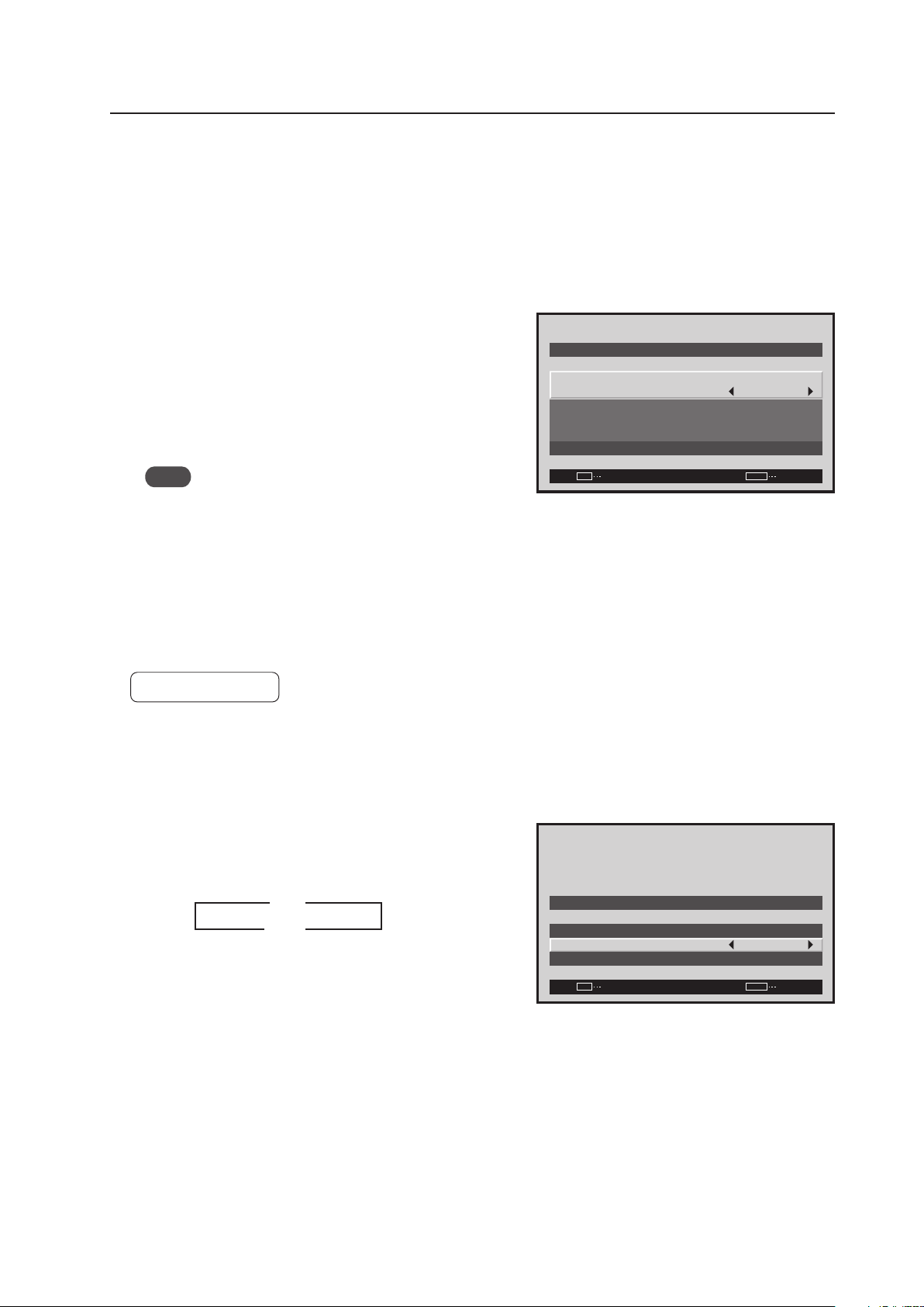
127
Menu Mode
10) Timer Setting
The present day of the week, time, and daylight savings time are set.
1 Select ‘OPTION’.
2 Select ‘TIMER SETTING’.
3 Set each item by pressing the 5/∞/2/3 buttons to move
the cursor to ‘PRESENT TIME’.
DAYLIGHT SAVING TIME ..... sets daylight savings time
ON: Displays time as present time + 1 hour
OFF: Disables [DAYLIGHT SAVING TIME] mode
Week ..................................... Set current day of the week
Hour, Minute ......................... Sets to current time.
Note
The set time may slow by approximately 1 minute per
month from the actual time.
The ‘TIMER SETTING’ is set for all inputs.
11) Program Timer Setting
The panel can be pre-programmed for a selected time.
Factory setting: OFF
1 Select ‘OPTION’.
2 Select ‘TIMER SETTING’.
3 Change the setting by pressing the 2/3 buttons to move
the cursor to the ‘PROGRAM TIMER’.
Each time a 2/3 button is pressed, the setting changes
as shown below.
PROGRAM TIMER Setting Example
•Every day, power turns on at 10:00
Input and function settings are the same as those set
the last time the unit was turned OFF.
•At 20:00 (8 o’clock PM), the screen turns white
At 21:00 (9 o’clock PM), power turns OFF
–
SET
EXIT
MENU
M O N D AY
1 2 : 0 0 : 0 0
S AV I N G T I M E
DAY L I G H T
S E T
R E T U R N
P R E S E N T T I M E
: O F F
Screen 3
Screen 3
–
SET
EXIT
MENU
T I M E R S E T T I N G
P R O G R A M T I M E R
R E T U R N
P R E S E N T T I M E
: O F F
3 ON
OFF 2
2
3

128
Menu Mode
12) PIP DETECT Setting
During picture-in-picture display, if no subscreen input signal is detected then the black borders of the subscreen are
automatically turned off.
The subscreen mode function is disabled during side-by-side display.
* The lack of a subscreen input signal means there is no video signal or sync signal.
Factory setting: ACTIVE
1 Select ‘OPTION’.
2 Place the cursor on ‘PIP DETECT’ then press the [SET]
button to change the setting.
Each time the [SET] button is pressed, the setting changes
as shown below.
• ACTIVE ...... When no subscreen input signal is input,
no subscreen is displayed. When the
subscreen input is later restored, the
subscreen is displayed again.
• INACTIVE .. When no subscreen signal is input, the
black border is visible.
The ‘PIP DETECT’ setting is common for all inputs.
Screen 2
M E N U IN P U T 1
CHANGE
SET
EXIT
MENU
S C R E E N S E T U P OPTI O N
L A N G U A G E
E N E R G Y S AV E
T I M E R S E T T I N G
S C R E E N M G T.
S P L I T F R E E Z E
A U T O S E T U P M O D E
A U T O F U N C T I O N
P I P D E T E C T
P I C T U R E
: S TA N D A R D
: I N A C T I V E
: O F F
: A C T I V E
: E N G L I S H
: O F F
3 ACTIVE
INACTIVE 2
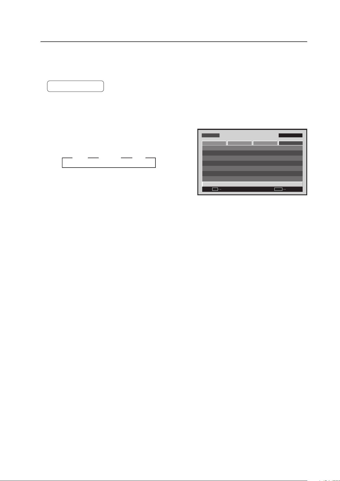
129
Menu Mode
13) SPLIT FREEZE Setting
For setting other than [OFF], the image displayed when the FREEZE button is pressed is displayed in a subscreen as
a freeze-frame image.
Factory setting: OFF
1 Select ‘OPTION’.
2 Place the cursor on ‘SPLIT FREEZE’ then press the [SET]
button to change the setting.
Each time the [SET] button is pressed, the setting changes
as shown below.
• OFF ........... The still picture displayed at the time the
FREEZE button was pressed is displayed
as a single fullscreen image
• S BY S ....... When the FREEZE button is pressed, the
freeze-frame image is displayed in the side-
by-side subscreen
• PIP ............. When the FREEZE button is pressed, the
freeze-frame image is displayed in the
picture-in-picture (left-bottom to left-top)
subscreen.
The ‘SPLIT FREEZE’ setting is common for all inputs.
Screen 2
MENU IN P UT1
CHANGE
SET
EXIT
MENU
SCREEN S E T U P OPTION
L A N G UAG E
E N E R G Y S AV E
T I M E R S E T T I N G
S C R E E N M G T.
AU T O S E T U P M O D E
AU T O F U N C T I O N
P I P D E T E C T
PICTURE
: S TA N DA R D
: I N AC T I V E
: O F F
: A C T I V E
: E N G L I S H
S P L I T F R E E Z E : O F F
3 OFF 3 S BY S 3 PIP
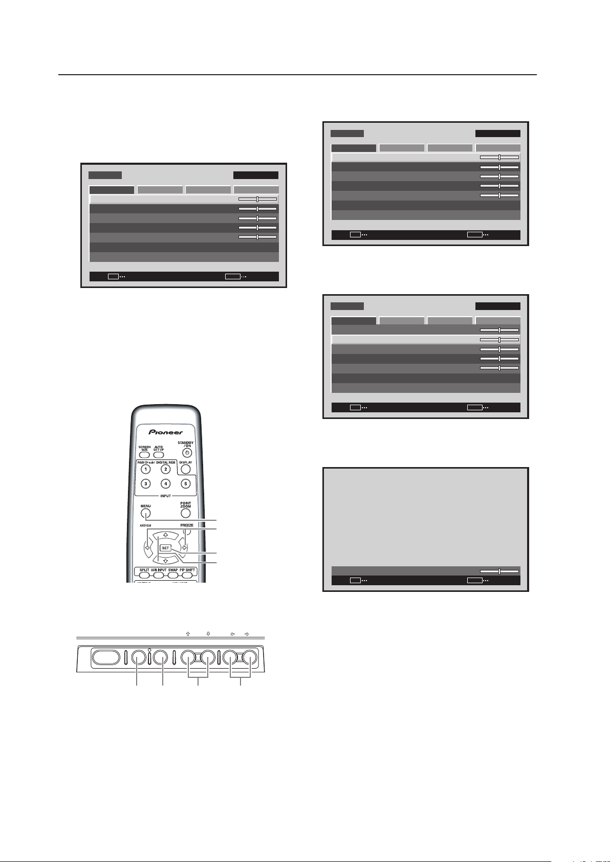
130
Menu Mode
5.3.6 Example of a Menu Mode Operation
The basic operation in the menu mode is explained using
brightness adjustment as an example.
MENU
5/∞
SET
2/3
Remote control unit
STANDBY/ON MENU
DISPLAY
/ SET
– VOL +INPUT SCREEN SIZE
�
2/3MENU SET 5/∞
Main-control panel
5.3.5 Concerning the display of the OSD of each
item (Applicable only when a PDA-5003/
PDA-5004 is installed.)
Example of Menu Display:
M E N U INPU T 1
ENTER
SET
EXIT
MENU
S C R E E N S E T U P O P T I O N
:
0
:
0
:
0
:
0
C O N T R A S T
:
0
B R I G H T N E S S
C O L O R
T I N T
S H A R P N E S S
P I C T U R E R E S E T
P I C T U R E
Images shown here may differ from the actual
display image.
1 Press the MENU button to display the menu
screen.
M E N U INPU T 1
ENTER
SET
EXIT
MENU
S C R E E N S E T U P O P T I O N
:
0
:
0
:
0
:
0
C O N T R A S T
:
0
B R I G H T N E S S
C O L O R
T I N T
S H A R P N E S S
P I C T U R E R E S E T
P I C T U R E
2 Use the 5/∞ buttons to select the adjustment
item then press the SET button.
M E N U INPU T 1
ENTER
SET
EXIT
MENU
S C R E E N S E T U P O P T I O N
:
0
:
0
:
0
C O N T R A S T
:
0
C O L O R
T I N T
S H A R P N E S S
P I C T U R E R E S E T
P I C T U R E
:
0
B R I G H T N E S S
3 Use the 2/3 buttons to adjust the picture
quality as desired.
:
0
B R I G H T N E S S
SET
SET
EXIT
MENU
It is possible to move to other adjustment items
with the 5/∞ buttons.
4 Press the SET button.
Pressing the SET button writes the value into the
memory and returns the display to the step 2
screen.
5 When the setup is finished, press the MENU
button to exit the menu screen.
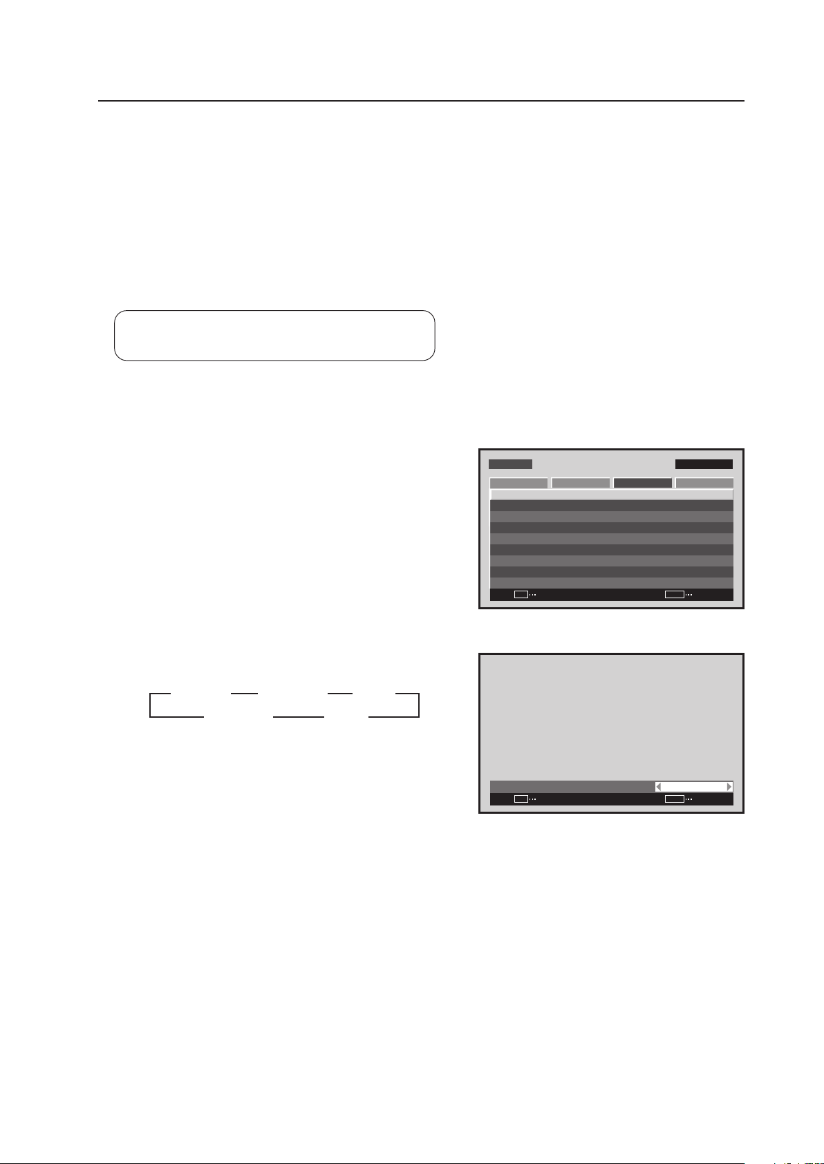
131
Menu Mode
5.3.7 Adjustment and setting in the Menu Mode
1) Color Temperature Setting
The color temperature of the video signal input can be set.
Setting should be performed for INPUT1 to INPUT5 in accordance with the following:
• LOW: Corresponds to – 2000 k
• MID LOW: Corresponds to – 1000 k
• MIDDLE: Corresponds to ± 0k (standard)
• MID HIGH: Corresponds to + 1000 k
• HIGH: Corresponds to + 2000 k
Settable condition: When there is video signal input
Factory setting: MIDDLE
1 Select ‘SETUP’.
2 Place the cursor over ‘COLOR TEMP.’ then press the [SET]
button.
3 Each time a [2/3] button is pressed, the setting changes
as shown below.
Screen 2
M E N U IN P U T 1
ENTER
SET
EXIT
MENU
S C R E E N S E T U P OPTI O NP I C T U R E
: D I S A B L E
: M I D D L E
C O L O R T E M P. : M I D D L E
AU T O P OW E R O F F
D N R
: L O W
: O N
M P E G N R
C T I
: O F F
: R G B
P U R E C I N E M A
C O L O R D E C O D I N G
: A U T OC O L O R S Y S T E M
S I G N A L F O R M AT
3 MIDDLE 2
3 MID LOW 2 3 LOW 2
3 MID HIGH 2 3 HIGH 2
:
C O L O R T E M P. MI D D L E
SET
SET
EXIT
MENU
Screen 3
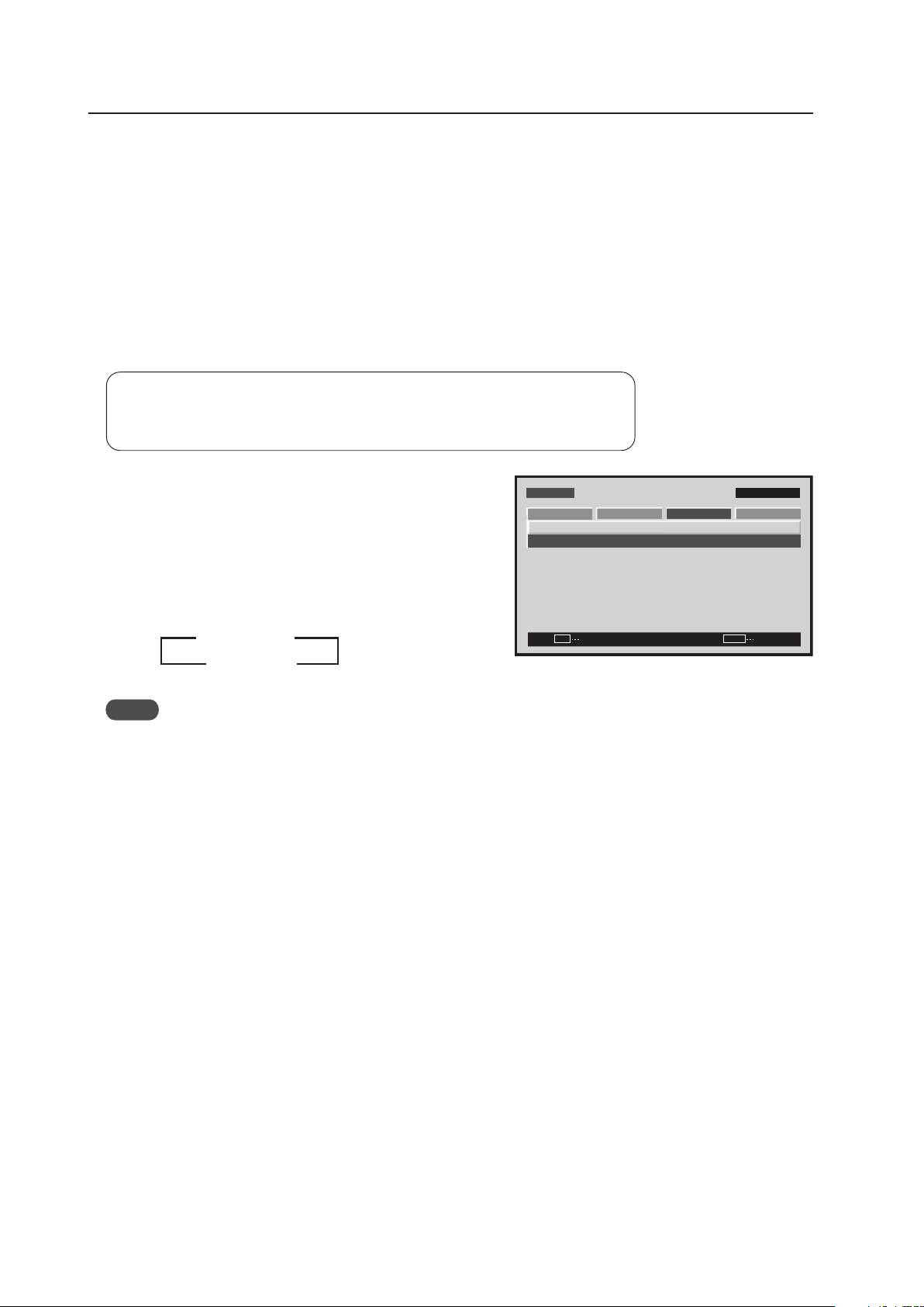
132
Menu Mode
2) Power Management and Auto Power OFF Setting
When no video signal (synchronizing signal) is detected, this function automatically sets the energy saving state in
order to save power.
• To disable the energy saving function, set to [OFF/DISABLE].
• When there is video signal input:
To set the power standby state when the input signal is not detected within 8 minutes, set ‘AUTO POWER OFF’
to [ENABLE].
• When there is PC signal input:
To switch between the normal-operation state and the energy saving state depending on whether or not there is
an input signal, set ‘POWER MANAGEMENT’ to [ON].
Settable condition : Power management: INPUT1, INPUT2 (PC signal), INPUT5
Auto power OFF: Conditions other than those above
Factory setting : OFF/DISABLE
Notes
• To return from the power standby state to the normal operation state, press the power button on the remote
control or the main control panel.
• To return from the energy saving state by power management to the normal operation state, operate the personal
computer or press the [INPUT] button on the remote control or main-control panel.
However, during SYNC ON G or composite SYNC input operation does not return by simply operating the personal
computer. After operating the personal computer, press the [INPUT] button.
• The power consumption during power standby.
PDP-425CMX: 1.2 W
PDP-42MXE10: 1.5 W
M E N U IN P U T 1
CHANGE
SET
EXIT
MENU
S C R E E N S E T U P OPTI O N
P O W E R M G T. : O F F
S I G N A L F O R M AT
P I C T U R E
3 OFF/DISABLE
ON/ENABLE 2
1 Select ‘SETUP‘.
2 Place the cursor over ‘POWER MANAGEMENT (AUTO
POWER OFF)’ and change the setting with the [SET]
button.
Each time the [SET] button is pressed, the setting is
changed as shown below.
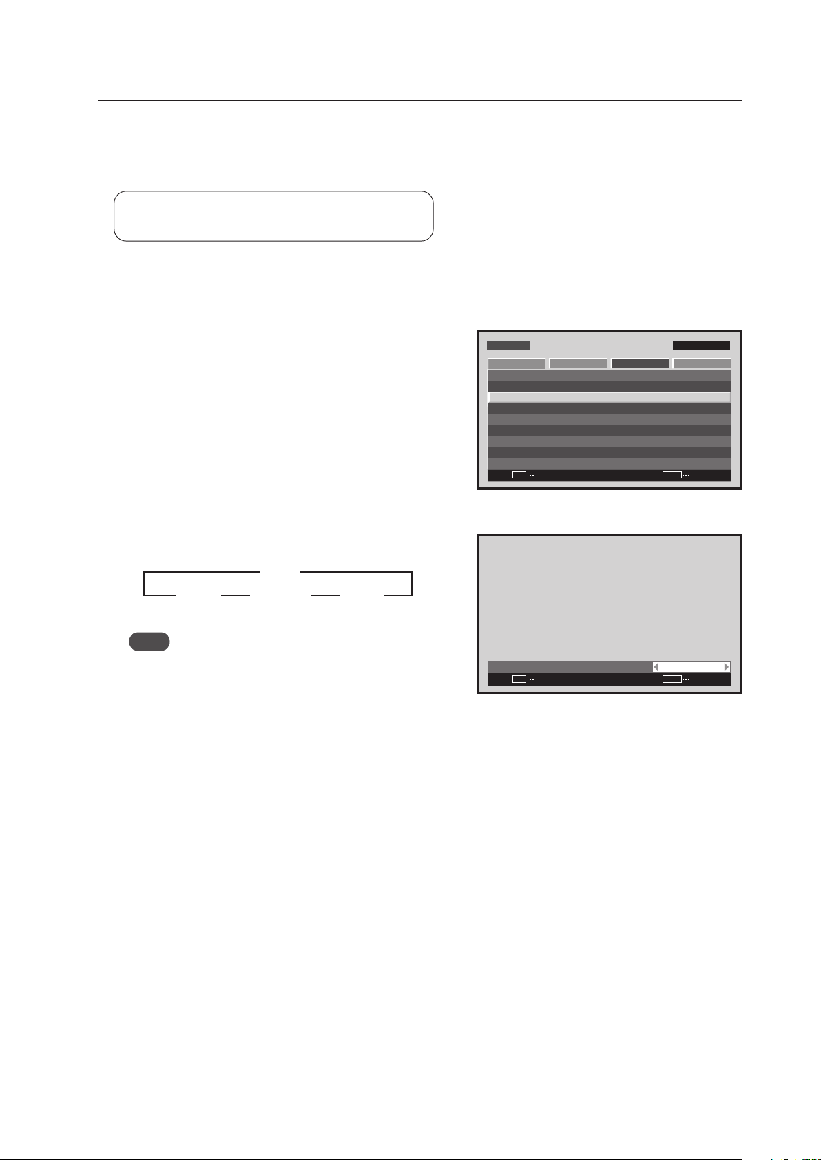
133
Menu Mode
3) DNR (digital noise reduction) Setting
The DNR (digital noise reduction) setting can be changed to improve the S/N ratio when a video signal is input. The
setting should be performed for each input (INPUT1 to INPUT 5) and each signal.
Settable conditions: When there is video signal input
Factory setting: MIDDLE
1 Select ‘SETUP’.
2 Place the cursor over ‘DNR’ then press the [SET] button.
3 Each time a [2/3] button is pressed, the setting changes
as shown below.
Note
DNR is unavailable during 1080p signal or multi screen
display.
M E N U IN P U T 1
ENTER
SET
EXIT
MENU
S C R E E N S E T U P O P T I O NP I C T U R E
: D I S A B L E
: M I D D L E
C O L O R T E M P. : M I D D L E
A U T O P O W E R O F F
D N R
: L O W
: O N
M P E G N R
C T I
: O F F
: R G B
P U R E C I N E M A
C O L O R D E C O D I N G
: A U T OC O L O R S Y S T E M
S I G N A L F O R M AT
Screen 2
:
D N R M I D D L E
SET
SET
EXIT
MENU
Screen 3
3 OFF 2
3 HIGH 2 3 MIDDLE 2 3 LOW 2
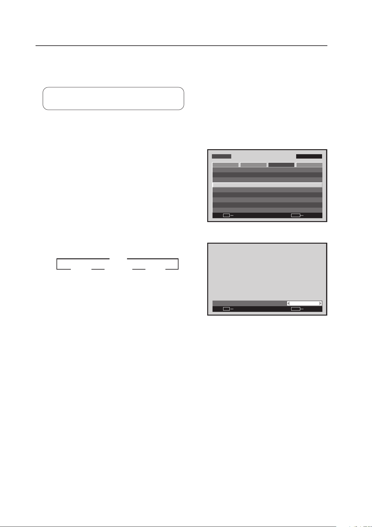
134
Menu Mode
4) MPEG NR Setting
This is set when the noise (mosquito noise) of the video such as in a digital broadcast or DVD is disturbing.
The setting should be performed for each input (INPUT1 to INPUT5) and each signal.
Settable condition: When there is video signal input
Factory setting: LOW
1 Select ‘SETUP’.
2 Place the cursor over ‘MPEG NR’ then press the [SET]
button.
3 Each time a [2/3] button is pressed, the setting changes
as shown below.
M E N U IN P U T 1
ENTER
SET
EXIT
MENU
S C R E E N S E T U P O P T I O NP I C T U R E
: D I S A B L E
: M I D D L E
C O L O R T E M P. : M I D D L E
A U T O P O W E R O F F
D N R
: L O W
: O N
M P E G N R
C T I
: O F F
: R G B
P U R E C I N E M A
C O L O R D E C O D I N G
: A U T OC O L O R S Y S T E M
S I G N A L F O R M AT
Screen 2
:
M P E G N R L O W
SET
SET
EXIT
MENU
Screen 3
3 OFF 2
3 HIGH 2 3 MIDDLE 2 3 LOW 2
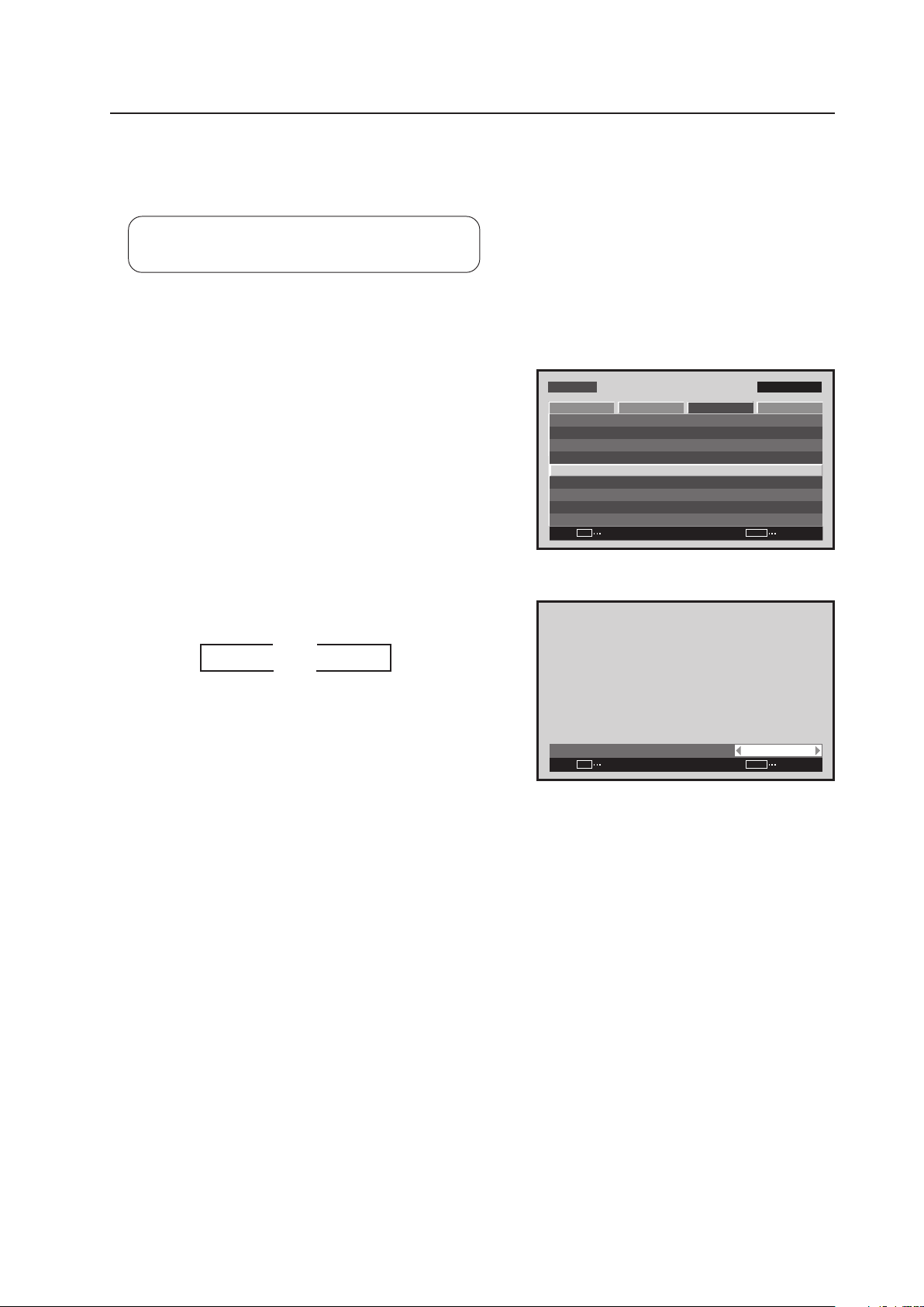
135
Menu Mode
5) CTI Setting
This setting sharpens the color contours as desired.
The setting should be performed for each input (INPUT1 to INPUT5) and each signal.
Settable condition: When there is video signal input
Factory setting: ON
1 Select ‘SETUP’.
2 Place the cursor over ‘CTI’ then press the [SET] button.
3 Each time a [2/3] button is pressed, the setting changes
as shown below.
M E N U IN P U T 1
ENTER
SET
EXIT
MENU
S C R E E N S E T U P OPTI O NP I C T U R E
: D I S A B L E
: M I D D L E
C O L O R T E M P. : M I D D L E
A U T O P O W E R O F F
D N R
: L O W
: O N
M P E G N R
C T I
: O F F
: R G B
P U R E C I N E M A
C O L O R D E C O D I N G
: A U T OC O L O R S Y S T E M
S I G N A L F O R M AT
Screen 2
:
C T I O N
SET
SET
EXIT
MENU
Screen 3
3 OFF 2
3 ON 2
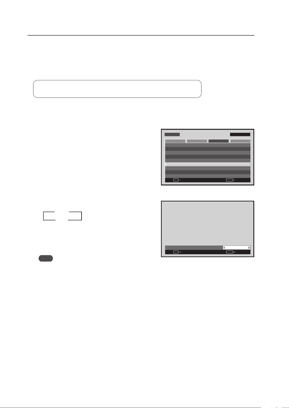
136
Menu Mode
6) PURECINEMA Setting
The PURECINEMA function automatically detects video signals such as movies that are filmed at 24 frames per
second then converts them to a progressive video signal by a 2-3 pull-down process. Normally, when the PURECINEMA
function is used, the ‘ON’ setting should be used.
The PURECINEMA setting should be performed for each input (INPUT1 to INPUT5) and each signal.
Settable condition: When there is INPUT1, INPUT3 to INPUT5 video signal input
Factory setting: OFF
1 Select ‘SETUP’.
2 Place the cursor over ‘PURECINEMA’ then press the [SET]
button.
3 Each time a [2/3] button is pressed, the setting changes
as shown below.
• OFF .................. I/P conversion is performed without
detecting the signal of the film source
• ON .................... The film source signal is detected then
the I/P is converted
Note
The modes that can be selected differ. Specific information is available on the next page.
3 OFF 2
3 ON 2
:
P U R E C I N E M A O F F
SET
SET
EXIT
MENU
Screen 3
M E N U IN P U T 1
ENTER
SET
EXIT
MENU
S C R E E N S E T U P OPTI O NP I C T U R E
: D I S A B L E
: M I D D L E
C O L O R T E M P. : M I D D L E
A U T O P O W E R O F F
D N R
: L O W
: O N
M P E G N R
C T I
: O F F
: R G B
P U R E C I N E M A
C O L O R D E C O D I N G
: A U T OC O L O R S Y S T E M
S I G N A L F O R M AT
Screen 2
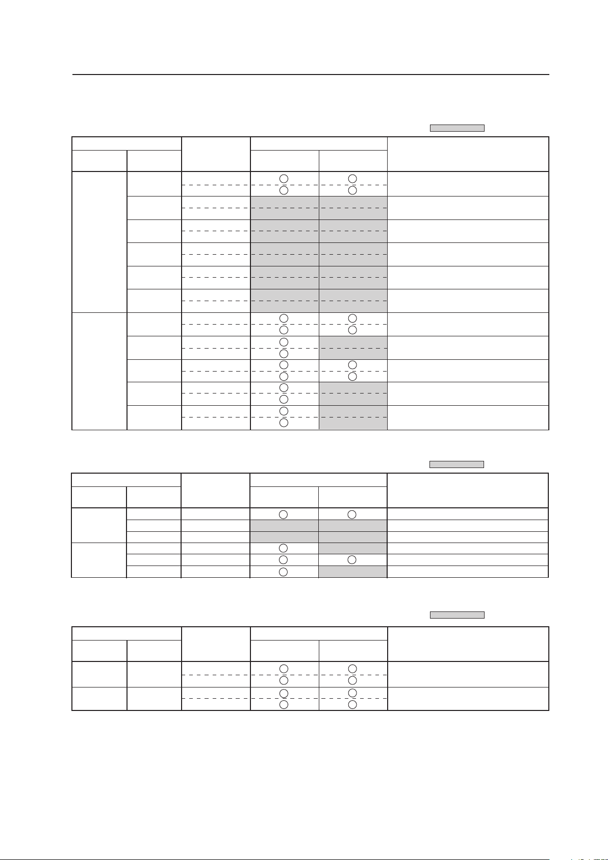
137
Menu Mode
Input Correspondence Signal
INPUT1, INPUT5
INPUT3, INPUT4
28.13
31.25
37.50
31.5
33.75
45.0
Vertical
f
V
(Hz)
Horizontal
f
H
(kHz)
Signal format
OFF ON
Types of display call signals
50
60
RGB
RGB
RGB
RGB
RGB
RGB
PURECINEMA
1125i (1080i)/HDT
V
625p (575p)/SDTV
750p (720p)/HDTV
525p (480p)/SDTV
1125i (1080i)/HDTV
750p (720p)/HDTV
Refresh rate
: Not available.
15.625
28.13
31.25
37.50
56.25
62.50
15.734
31.5
33.75
45.0
67.5
Vertical
f
V
(Hz)
Horizontal
f
H
(kHz)
Signal format
OFF ON
Types of display call signals
50
60
Component
RGB
Component
RGB
Component
RGB
Component
RGB
Component
RGB
Component
RGB
Component
RGB
Component
RGB
Component
RGB
Component
RGB
Component
RGB
PURECINEMA
625i (576i)/SDTV
1125i (1080i)/HDTV
625p (576p)/SDTV
750p (720p)/HDTV
1125p (1080p)/HDTV
1250p/HDTV
525i (480i)/SDTV
525p (480p)/SDTV
1125i (1080i)/HDTV
1125i (1035i)/HDTV
750p (720p)/HDTV
1125p (1080p)/HDTV
Refresh rate
: Not available.
15.625
15.734
Vertical
f
V
(Hz)
Horizontal
f
H
(kHz)
Signal format
OFF ON
50
60
Composite
S Video
Composite
S Video
PURECINEMA
PAL, SECAM, PAL-N
(black & white 50 Hz)
NTSC, 4.43 NTSC, PAL-M
(black & white 60 Hz)
Refresh rate
: Not available.
Types of display call signals
INPUT2
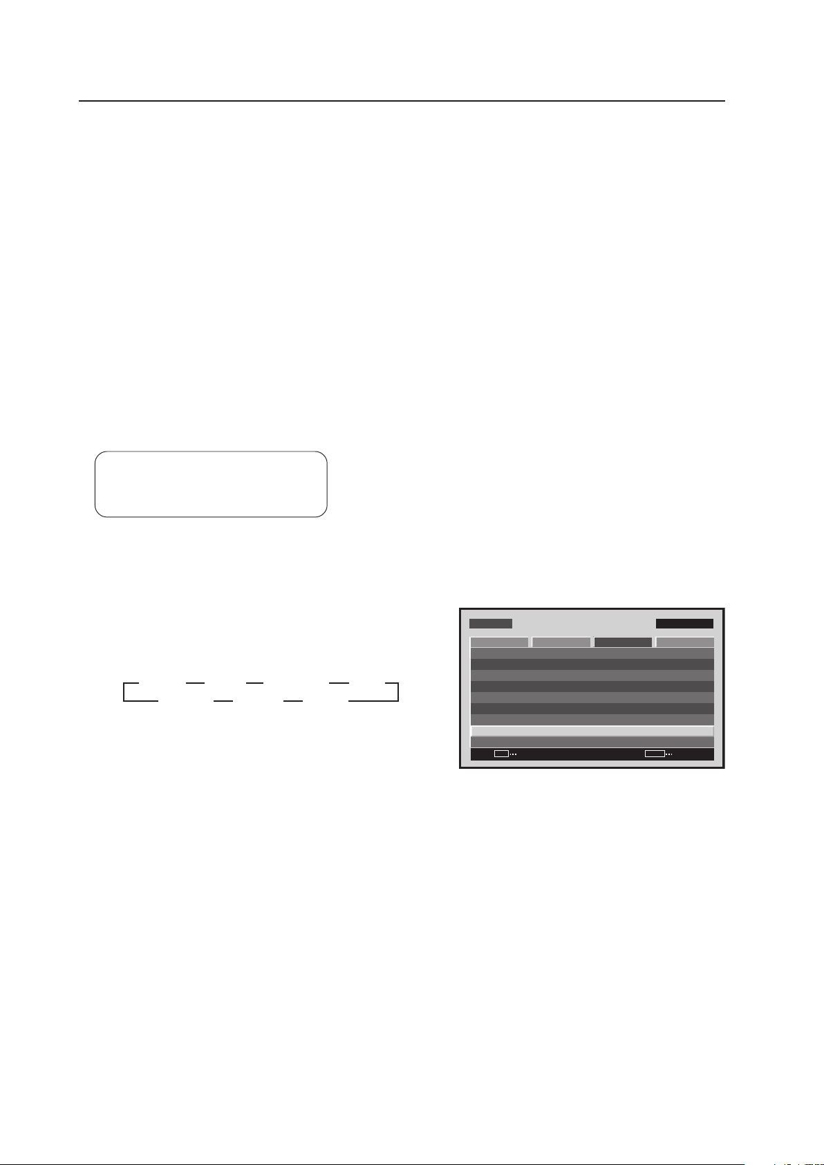
138
Menu Mode
7) Color System Setting
INPUT3 and INPUT4 correspond to and automatically determine the various TV systems used in countries around
the world.
Normally, this setting is set to ‘COLOR SYSTEM: AUTO (Auto detection)’, however, in the case of VTR signals with
repeated dubbings, proper reproduction of the signal may not be possible (no color, etc.).
In this case, the setting needs to correspond to the input signal as follows.
The setting should be performed for INPUT3 and INPUT4.
• For NTSC signal input: Set ‘COLOR SYSTEM: NTSC’.
• For PAL signal input: Set ‘COLOR SYSTEM: PAL’.
• For SECAM signal input: Set ‘COLOR SYSTEM: SECAM’.
• For 4.43NTSC signal input: Set ‘COLOR SYSTEM: 4.43NTSC’.
• For PAL-M signal input: Set ‘COLOR SYSTEM: PAL M’.
• For PAL-N signal input: Set ‘COLOR SYSTEM: PAL N’.
By fixing the settings when the input signal is already known in advanced, it is possible to perform smooth image
processing and to prevent signal confusion.
Settable condition: INPUT3, INPUT4
Factory setting: INPUT3: AUTO
INPUT4: AUTO
1 Select ‘SETUP’.
2 Place the cursor over ‘COLOR SYSTEM’ then press the
[SET] button to change the setting.
Each time the [SET] button is pressed, the setting changes
as shown below.
MENU IN P UT1
ENTER
SET
EXIT
MENU
SCREEN S E T U P OPTIONPICTURE
: D I S A B L E
: M I D D L E
C O L O R T E M P. : M I D D L E
AU T O P OW E R O F F
D N R
: L OW
: O N
M P E G N R
C T I
: O F F
: R G B
P U R E C I N E M A
C O L O R D E C O D I N G
: AU TOC O L O R S Y S T E M
S I G N A L F O R M AT
Screen 2
3
AUTO
3
NTSC
3
4.43 NTSC
3
PAL
SECAM 2 PAL M 2 PAL N 2

139
Menu Mode
8) Signal Format Setting
This display automatically identifies PC signals and video signals such as from a DVD player by the frequency of the
input signal. The panel is equipped with a function for identifying the resolution of a PC signal.
Factory setting: AUTO
1 Select ‘SETUP’.
2 Place the cursor over ‘SIGNAL FORMAT’ then press the
[SET] button.
3 Press the [2/3] buttons to change the setting.
Each time a [2/3] button is pressed, the signal format
changes as shown below.
• AUTO ........ It is distinguished as in “5.1.3 List of
Input Correspondence Signals 2) Input
correspondence signals personal
computer signals” (pages 95 to 97)
• Others ....... Selectable resolutions are displayed
Note
The display method and selectable screen size differs for each setting. In order to obtain a proper reproduction
method and screen size, check the signal format setting when the signal is input. Change the setting as necessary.
M E N U IN P U T 1
ENTER
SET
EXIT
MENU
S C R E E N S E T U P OPTI O N
: D I S A B L E
: M I D D L E
C O L O R T E M P. : M I D D L E
AU T O P OW E R O F F
D N R
: L O W
: O N
M P E G N R
C T I
: O F F
: R G B
P U R E C I N E M A
C O L O R D E C O D I N G
: A U T OC O L O R S Y S T E M
S I G N A L F O R M AT
P I C T U R E
Screen 2
:
S I G N A L F O R M AT
A U T O
SET
SET
EXIT
MENU
Screen 3
3 AUTO
Others 2
2
3
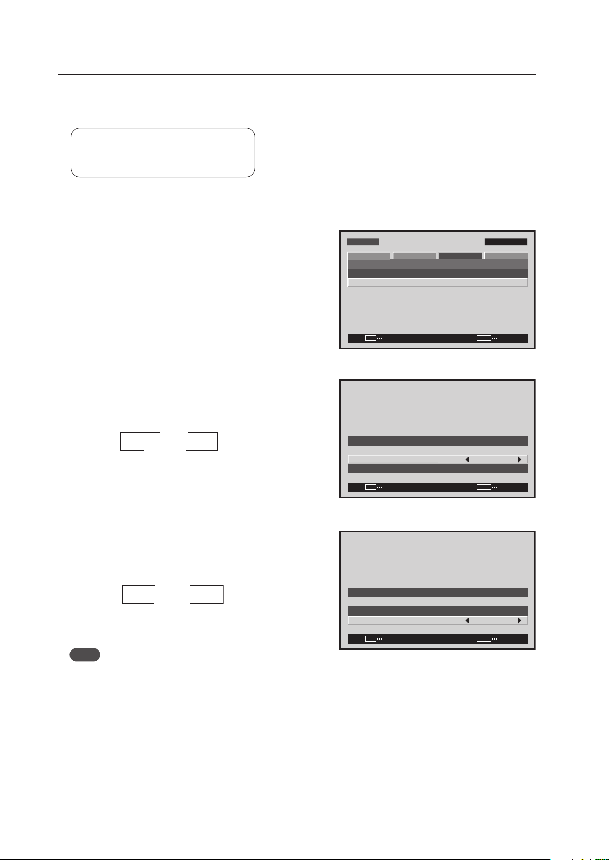
140
Menu Mode
9) DVI Setting
Choose the component type (either [PC] or [VIDEO]) that is connected to INPUT2.
Settable condition: INPUT2
Factory setting: PLUG/PLAY: PC
BLACK LEVEL: LOW
1 Select ‘SETUP’.
2 Select ‘DVI SET UP’.
3 Place the cursor over ‘PLUG/PLAY’ and press the [2/3]
button to change the setting.
Each time a [2/3] button is pressed, the setting changes
as shown below.
* Applicable only when the video card is installed.
4 Place the cursor over ‘BLACK LEVEL’ then press the [2/3]
button to change the setting.
Each time the [2/3] button is pressed, the setting
changes as shown below.
Note
When ‘PLUG/PLAY’ is set to ‘VIDEO’ then ‘BLACK LEVEL’ is set to ‘HIGH’. However, there are devices that can
adjust BLACK LEVEL so confirm the setting on the device.
M E N U IN P U T 1
SET
EXIT
MENU
S C R E E N S E T U P OPTI O N
P O W E R M G T. : O F F
S I G N A L F O R M AT
P I C T U R E
D V I S E T U P
ENTER
Screen 2
Screen 3
3 PC
VIDEO* 2
2
3
SET
SET
EXIT
MENU
DV I S E T U P
P L U G / P L AY
B L A C K L E V E L
: P C
: L OW
Screen 4
SET
SET
EXIT
MENU
DV I S E T U P
P L U G / P L AY
B L A C K L E V E L
: P C
: L OW
3
3
LOW
HIGH 2
2
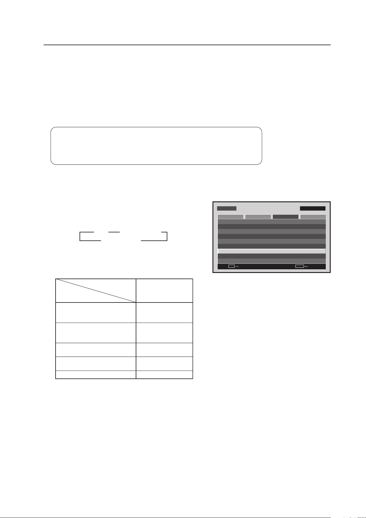
141
Menu Mode
10) Color Decoding Setting
When a video signal is input at INPUT1, INPUT2 and INPUT5, it corresponds to an RGB and component video signal.
This setting must comply with the connected device.
The setting should be performed as shown below for INPUT1, INPUT2, and INPUT5.
(Example)
• When reproducing an RGB signal: Set to ‘COLOR DECODING: RGB’.
• For reproduction from a DVD player: Set to ‘COLOR DECODING: COMPONENT1’.
Settable condition: INPUT1, INPUT2, INPUT5
When a video signal (signal other than a PC signal) is input
Factory setting: For 525i, 525p, 625i, 625p signal input: COMPONENT1
For 750p, 1125i, 1125p, 1250p signal input: COMPONENT2
1 Select ‘SETUP’.
2 Place the cursor over ‘COLOR DECODING’ then press
the [SET] button to change the setting.
Each time the [SET] button is pressed, the setting changes
as shown below.
Set ‘COLOR DECODING‘ as follows.
Please take care when assigning settings. Incorrect
settings can adversely affect the Plasma Display.
M E N U IN P U T 1
CHANGE
SET
EXIT
MENU
S C R E E N S E T U P O P T I O N
: D I S A B L E
: M I D D L E
C O L O R T E M P. : M I D D L E
A U T O P O W E R O F F
D N R
: L O W
: O N
M P E G N R
C T I
: O F F
: R G B
P U R E C I N E M A
C O L O R D E C O D I N G
: A U T OC O L O R S Y S T E M
S I G N A L F O R M AT
P I C T U R E
Screen 2
3
RGB
COMPONENT22
3
COMPONENT1
Component video output of
Y/Cb/Cr format.
For example, DVD player, etc.
Component video output of
Y/Pb/Pr format.
For example, digital tuner, etc.
RGB video output of a video deck
etc., with RGB output
DVI video output of an AV
component with DVI output port
RGB video output of a PC
Connected
component
COLOR DECODING
SETUP
COMP.1
COMP.2
RGB
RGB
Not supported
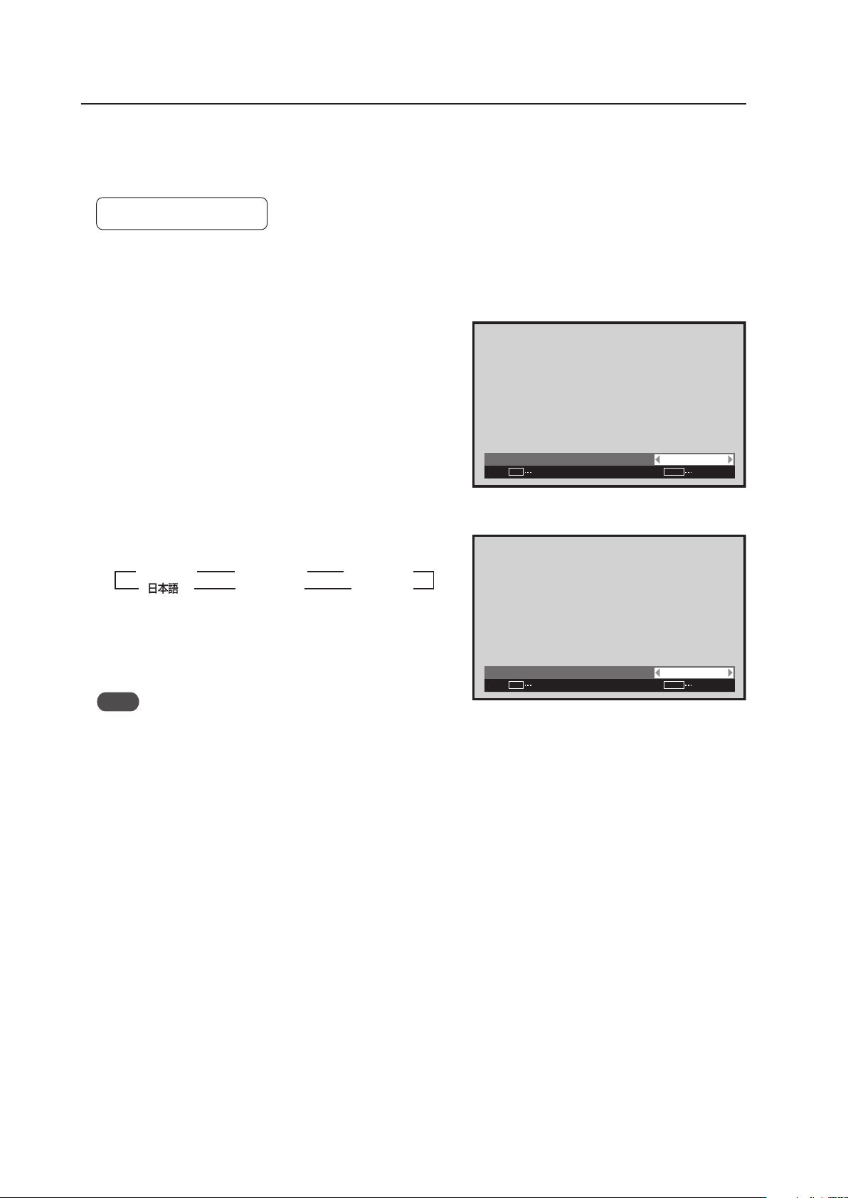
142
Menu Mode
11) Menu Language Display Setting
The factory setting for the menu display language is English. To change to another language it is necessary to
change the setting.
Factory setting: ENGLISH
1 Select ‘OPTION’.
2 Place the cursor over ‘LANGUAGE’ then press the [SET]
button.
3 Each time a [2/3] button is pressed, the language
changes as shown below.
With the desired language displayed, press the [SET]
button.
Note
When the screen display language is set for either INPUT1 to INPUT5, the same display language is set for both
inputs.
:
L A N G U A G E E N G L I S H
SET
SET
EXIT
MENU
Screen 3
3
ENGLISH
2 3
ESPAÑOL
2
3
DEUTSCH
2
3
3
FRANÇAIS
2
3
2
ITALIANO
2
Screen 2
:
LA N G UAG E F R A NÇA I S
SET
SET
EXIT
MENU
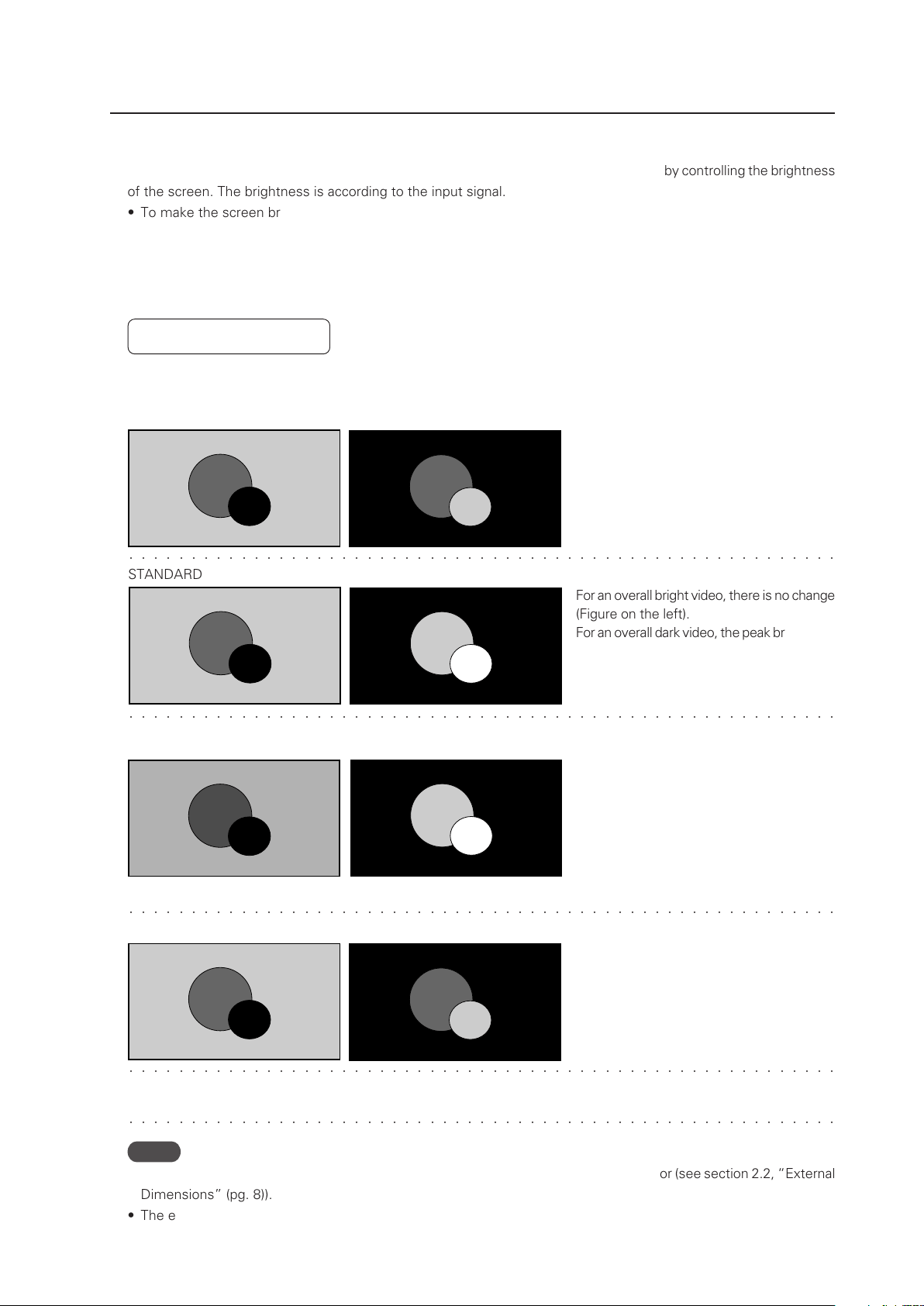
143
Menu Mode
� � � � � � � � � � � � � � � � � � � � � � � � � � � � � � � � � � � � � � � � � � � � � � � � � � � � � � � � �
� � � � � � � � � � � � � � � � � � � � � � � � � � � � � � � � � � � � � � � � � � � � � � � � � � � � � � � � �
STANDARD
For an overall bright video, there is no change
(Figure on the left).
For an overall dark video, the peak brightness
is reproduced even brighter (Figure on the
right).
MODE1, MODE2
MODE3
Power consumption is lowered by reducing
the brightness of an overall bight video
(Figure on the left).
Similar to in the STANDARD setting, an overall
dark video is peak brightness is reproduced
even brighter (Figure on the right).
The peak brightness in MODE2 is decreased
by a set amount with respect to that in
MODE1, however it is reproduced brighter
than in MODE3.
Input signal graduation is not controlled but
reproduced accurately. Deterioration of the
panel due to burning is reduced since the
peak brightness of an overall dark video is
not increased.
� � � � � � � � � � � � � � � � � � � � � � � � � � � � � � � � � � � � � � � � � � � � � � � � � � � � � � � � �
� � � � � � � � � � � � � � � � � � � � � � � � � � � � � � � � � � � � � � � � � � � � � � � � � � � � � � � � �
12) Energy Saving Setting
This is a function that reduces power consumption and reduces deterioration of the panel by controlling the brightness
of the screen. The brightness is according to the input signal.
• To make the screen bright and easy to see: Set ‘ENERGY SAVE: STANDARD’
• To reduce power consumption: Set ‘ENERGY SAVE: MODE1, MODE2’
• To reduce deterioration of the panel such as burning: Set ‘ENERGY SAVE: MODE 3’
• To perform control according to the brightness of the room and to adjust the screen according to the surroundings:
Set ‘ENERGY SAVE: AUTO’
Factory setting: STANDARD
Differences in video reproduction by energy saving settings (illustration)
For this kind of input signal
� � � � � � � � � � � � � � � � � � � � � � � � � � � � � � � � � � � � � � � � � � � � � � � � � � � � � � � � �
AUTO The brightness is automatically changed within the STANDARD (bright) to MODE2 (dark) range according
to the brightness of the room.
Notes
• When AUTO is set, do not place objects near or let light shine directly on external sensor (see section 2.2, “External
Dimensions” (pg. 8)).
• The external sensor changes in stages; from an external light of 200 lux (rough value) to external light of 0 lux.
XXXXXXXXX.
(As a standard)
When the white window is displayed, the
peak brightness is decreased as shown
below.
• MODE1: Decreased about 50%
• MODE2: Decreased about 60%
• MODE3: Decreased about 75%

144
Menu Mode
1 Select ‘OPTION’.
2 Place the cursor over ‘ENERGY SAVE’ then press the [SET]
button to change the setting.
Each time the [SET] button is pressed, the setting changes
as shown below.
The ‘ENERGY SAVE’ setting is common for all inputs.
MENU INPUT1
CHANGE
SET
EXIT
MENU
SCREEN SETUP OPTION
LA N G U AGE
EN E R G Y S AV E
TI M E R SE T T I NG
SC R E E N M G T.
SP L I T FR E E Z E
AU TO S E T UP MOD E
AU TO F U N CTI O N
PI P D E T E CT
PICTURE
:S TAN DAR D
:I N A C TIV E
:O F F
:A C T I VE
:E N G L ISH
:O F F
Screen 2
3 STANDARD
MODE2 2 MODE1 2
3 AUTO
MODE3 2
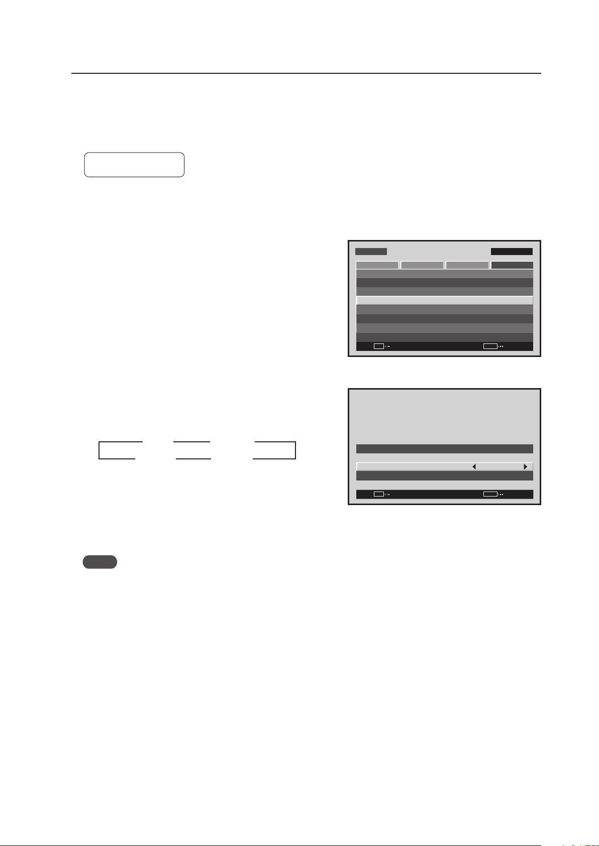
145
Menu Mode
13) Orbiter Setting
This function gradually moves the display position of the screen periodically screen position is moved at random,
horizontally or vertically).
Setting ‘MODE1’ to ‘MODE3’ is effective in reducing screen burn when a still image is displayed.
Factory setting: OFF
1 Select ‘OPTION’.
2 Select ‘SCREEN MGT.’.
2 Place the cursor on ‘ORBITER’ then press the [2/3]
buttons to change the settings.
Each time a [2/3] button is pressed, the setting changes
as shown below.
MODE1 ....... The size is reduced so the picture is
completely in the display area.
MODE2 ....... The size is increased so there are no black
bands in the display area.
MODE3 ....... It is displayed at the same size.
Notes
• When ‘MODE1’ or ‘MODE2’ has been set, it moves smoothly.
• In ‘MODE3’, it moves in dot units. The entire screen moves 1 dot horizontally or vertically approximately every
minute. The maximum movement is 4 dots.
• When it is set to ‘OFF’, the orbiter of the PIP subscreen is ON.
The ‘ORBITER’ setting is common for all inputs.
Screen 2
MENU INPUT1
ENTER
SET
EXIT
MENU
SCREEN SETUP OPTION
LA N G U AGE
EN E R G Y S AV E
TI M E R SE T T I NG
SC R E E N M G T.
SP L I T FR E E Z E
AU TO S E T UP MOD E
AU TO F U N CTI O N
PI P D E T E CT
PICTURE
:S TAN DAR D
:I N A C TIV E
:O F F
:A C T I VE
:E N G L ISH
:O F F
Screen 3
SET
SET
EXIT
MENU
SC R E E N M A N AGE M E NT
OR B I T ER
SO F T FOC U S
: O F F
: O F F
3 OFF
MODE3 2
2
MODE2 2
3
3
3
MODE1
2
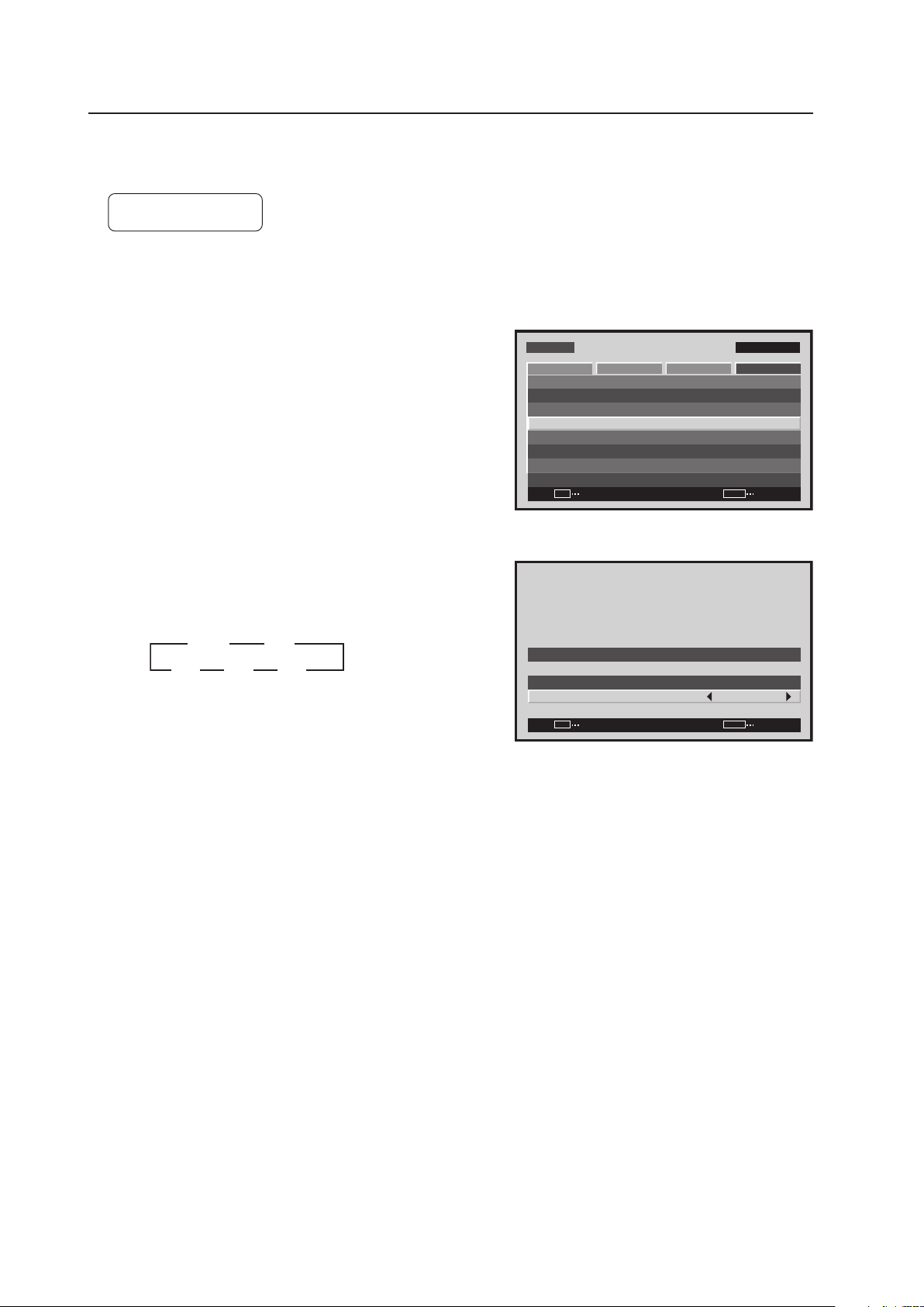
146
Menu Mode
14) Soft Focus Setting
Images are softened by suppressing the edge contrast.
Factory setting: OFF
1 Select ‘OPTION’.
2 Select ‘SCREEN MGT.’.
2 Place the cursor on ‘SOFT FOCUS’ then press the [2/3]
buttons to change the settings.
Each time a [2/3] button is pressed, the setting changes
as shown below.
The ‘SOFT FOCUS’ setting is common for all inputs.
Screen 2
MENU INPUT1
ENTER
SET
EXIT
MENU
SCREEN SETUP OPTION
LA N G U AGE
EN E R G Y S AV E
TI M E R SE T T I NG
SC R E E N M G T.
SP L I T FR E E Z E
AU TO S E T UP MOD E
AU TO F U N CTI O N
PI P D E T E CT
PICTURE
:S TAN DAR D
:I N A C TIV E
:O F F
:A C T I VE
:E N G L ISH
:O F F
Screen 3
SET
SET
EXIT
MENU
SC R E E N M A N AGE M E NT
OR B I T ER
SO F T FOC U S
: O F F
: O F F
3 OFF
4 2
3 1
3 2
2
2 2
2
3 3 3

147
Menu Mode
15) Auto Set Up Mode Setting
This function automatically adjusts the signal when the power is turned ON, when input is changed, and when the
type of input signal is changed.
Factory setting: INACTIVE
1 Select ‘OPTION’.
2 Place the cursor on ‘AUTO SET UP MODE’ then press
the [SET] button to change the setting.
Each time the [SET] button is pressed, the setting changes
as shown below.
Notes
• This setting is only effective when a PC signal is input to INPUT1 or INPUT5.
• Items 1 and 3 below are adjusted automatically.
‘SCREEN’ Adjustment inside the menu: 1. ‘POSITION’
2. ‘CLOCK’
3. ‘PHASE’
• The adjustment items are the same as when the ‘AUTO SET UP’ button is pressed on the remote control. However,
the screen may be less precise. This difference in precision is due to short processing time in the AUTO SET UP
MODE.
• It may not be possible to precisely adjust an input signal such as when the signal has low brightness. Set the
AUTO SET UP MODE to INACTIVE then adjust as explained in the following section, ‘SCREEN, CLOCK, PHASE’.
• When the AUTO SET UP MODE is set to ACTIVE and the ‘SCREEN’ is adjusted manually, ‘AUTO SET UP MODE:
ACTIVE’ is displayed.
This is to warn you that although adjustment is manual, when the input changes, or when the type of signal
changes on the outside, the AUTO SET UP MODE functions and the adjusted values are overwritten.
MENU INPUT1
CHANGE
SET
EXIT
MENU
SCREEN SETUP OPTION
LA N G U AGE
EN E R G Y S AV E
TI M E R SE T T I NG
SC R E E N M G T.
SP L I T FR E E Z E
AU TO S E T UP MOD E
AU TO F U N CTI O N
PI P D E T E CT
PICTURE
:S TAN DAR D
:I N A C TIV E
:O F F
:A C T I VE
:E N G L ISH
:O F F
Screen 2
3 INACTIVE
ACTIVE 2
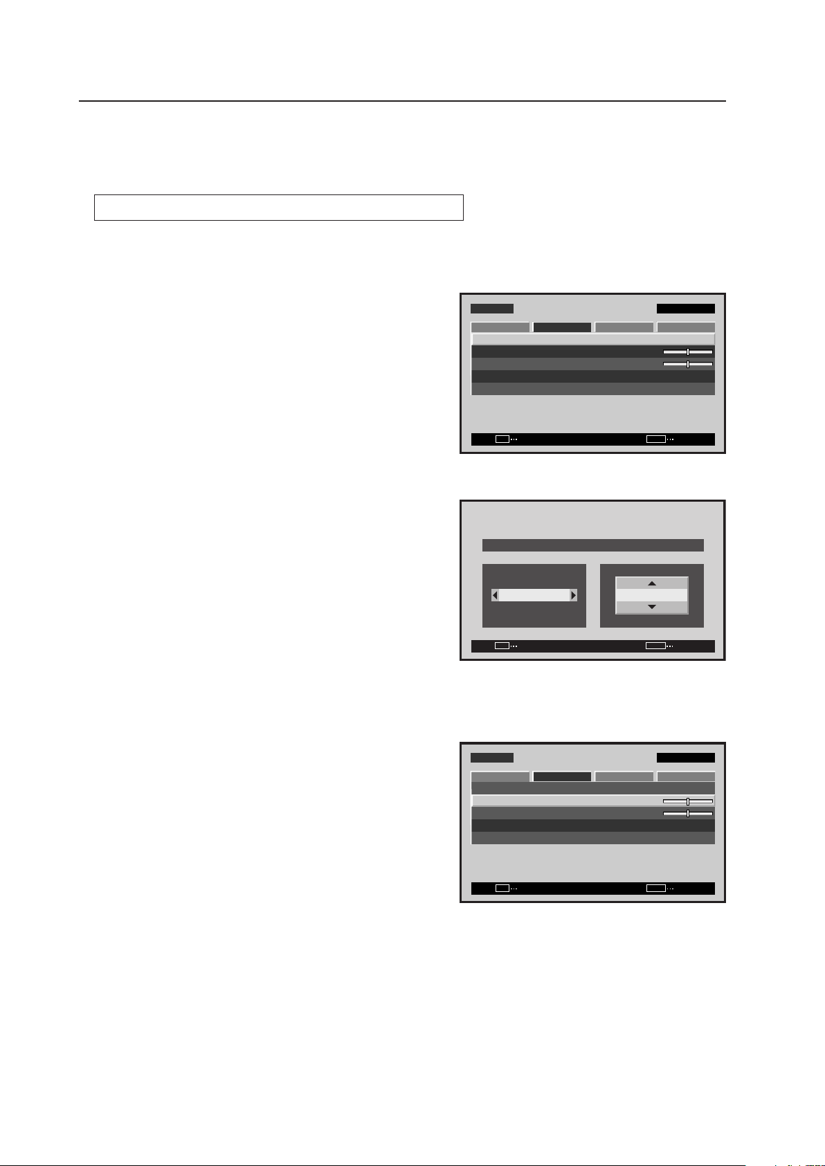
148
Menu Mode
16) Screen Position, Clock Frequency and Clock Phase Adjustment
In AUTO SET UP, the position and clock are optimally set. However, depending on the type of signal, adjustment
may be off. In this situation, manually adjust the setting.
Example) When a PC signal is input to INPUT1 (1024 x 768)
1 Set the screen size to ‘DOT BY DOT’.
2 Select ‘SCREEN’.
3 Place the cursor on ‘POSITION’ then press the [SET]
button.
4 Use the [5/∞] and [2/3] buttons to adjust the screen
position.
Here, the top and left side of the video display are properly
set.
1. With the [∞] button, lower the display until the mask
(black portion) protrudes into the top of the image.
2. With the [5] button, move the display to the point
where the mask at the top disappears.
3. With the [3] button, move the display until the mask
(black portion) protrudes into the right side of the image.
4. With the [2] button, move the display to the point
where the mask on the left side disappears.
5 Place the cursor on ‘CLOCK’ then press the [SET] button.
M E N U IN P U T 1
ENTER
SET
EXIT
MENU
S C R E E N S E T U P OPTI O N
:
0
:
0
P O S I T I O N
:
0 / 0
C L O C K
P H A S E
S C R E E N R E S E T
P I C T U R E
Screen 2
Screen 4
SET
SET
EXIT
MENU
P O S I T I O N
H V
+ 8 8+ 8 8
Screen 5
M E N U IN P U T 1
ENTER
SET
EXIT
MENU
S C R E E N S E T U P OPTI O N
:
:
0
P O S I T I O N
:
0 / 0
C L O C K
P H A S E
S C R E E N R E S E T
P I C T U R E
0

149
Menu Mode
6 Use the [2/3] buttons to adjust the click frequency.
In step 4, the left side was aligned. Here the right side is
aligned.
1. With the [3] button, move the display until the mask
(black portion) protrudes into the right side of the image.
2. With the [2] button, move the display to the point
where the mask on the right side disappears.
7 In the adjustment in steps 5 and 6, the left side of the screen moves. With ‘POSITION’, accurately adjust the left
side of the video display again.
As in step 4, used the [2/3] buttons to align the left side.
8 In the adjustment in step 7, the right side of the screen moves. With ‘CLOCK’, adjust the right side again.
As in step 6, use the [2/3] buttons to align the left side.
Repeat steps 7 and 8 until the adjustment value converges then adjust the ‘PHASE’.
There are vertical lines, so it is easier to adjust the screen if the input signal has edges.
9 Place the cursor on ‘PHASE’ then press the [SET] button.
0 Using the [2/3] buttons to adjust the clock phase.
Move the vertical edge of the image to the point where it becomes bold.
Adjustment is now complete.
:
0
C L O C K
SET
SET
EXIT
MENU
Screen 6

150
Menu Mode
17) Auto Function Mode Setting
With the Auto Function mode it is possible to automatically change the input when a signal is detected.
Factory setting: OFF
1 Select ‘OPTION’.
2 Place the cursor over ‘AUTO FUNCTION’ then press the
[SET] button to change the setting.
Each time the [SET] button is pressed, the setting changes
as shown below.
• When INPUT1 or INPUT4 is selected, this function
automatically switches to that input when the signal is
detected. Also, in the Auto Function mode, after the input
switches and the signal input stops, the Auto Function
returns to the input that was used before the switch.
Notes
• The Auto Function mode is unavailable when ‘OFF’ is selected.
• When SYNC ON G or a component signal is input to INPUT1, the Auto Function is unavailable.
• After the input has been switched in the Auto Function mode, press the [INPUT] button and select a different
input. The Auto Function mode activates when it detects a change in the selected input signal (from a no-input
state to an input state).
• When the power is turned OFF/ON, the Auto Function mode activates when the signal is input to the selected
input.
• The Auto Function mode is unavailable when the Menu displays, during POINT ZOOM, or during multi-screen
display.
• When the Auto Function mode is set to ‘INPUT1’ or ‘INPUT4’, ‘AUTO’ appears under the option that displays the
selected input (INPUT1 to INPUT5).
• When a video card other than a PDA-5003/PDA-5004 is installed, the Auto Function mode does not function even
when set to ‘INPUT4’.
Screen 2
M E N U IN P U T 1
CHANGE
SET
EXIT
MENU
S C R E E N S E T U P OPTI O N
L A N G U A G E
E N E R G Y S AV E
T I M E R S E T T I N G
S C R E E N M G T.
S P L I T F R E E Z E
A U T O S E T U P M O D E
A U T O F U N C T I O N
P I P D E T E C T
P I C T U R E
: S TA N D A R D
: I N A C T I V E
: O F F
: A C T I V E
: E N G L I S H
: O F F
3 OFF
3 INPUT1
INPUT4 2
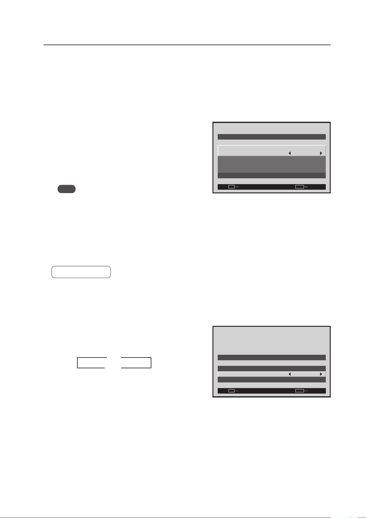
151
Menu Mode
18) Timer Setting
The present day of the week, time, and daylight savings time are set.
1 Select ‘OPTION’.
2 Select ‘TIMER SETTING’.
3 Set each item by pressing the 5/∞/2/3 buttons to move
the cursor to ‘PRESENT TIME’.
DAYLIGHT SAVING TIME ..... sets daylight savings time
ON: Displays time as present time + 1 hour
OFF: Disables [DAYLIGHT SAVING TIME] mode
Week ..................................... Set current day of the week
Hour, Minute ......................... Sets to current time.
Note
The set time may slow by approximately 1 minute per
month from the actual time.
The ‘TIMER SETTING’ is set for all inputs.
19) Program Timer Setting
The panel can be pre-programmed for a selected time.
Factory setting: OFF
1 Select ‘OPTION’.
2 Select ‘TIMER SETTING’.
3 Change the setting by pressing the 2/3 buttons to move
the cursor to the ‘PROGRAM TIMER’.
Each time a 2/3 button is pressed, the setting changes
as shown below.
PROGRAM TIMER Setting Example
•Every day, power turns on at 10:00
Input and function settings are the same as those set
the last time the unit was turned OFF.
•At 20:00 (8 o’clock PM), the screen turns white
At 21:00 (9 o’clock PM), power turns OFF
–
SET
EXIT
MENU
M O N D AY
1 2 : 0 0 : 0 0
S AV I N G T I M E
DAY L I G H T
S E T
R E T U R N
P R E S E N T T I M E
: O F F
Screen 3
Screen 3
–
SET
EXIT
MENU
T I M E R S E T T I N G
P R O G R A M T I M E R
R E T U R N
P R E S E N T T I M E
: O F F
3 ON
OFF 2
2
3
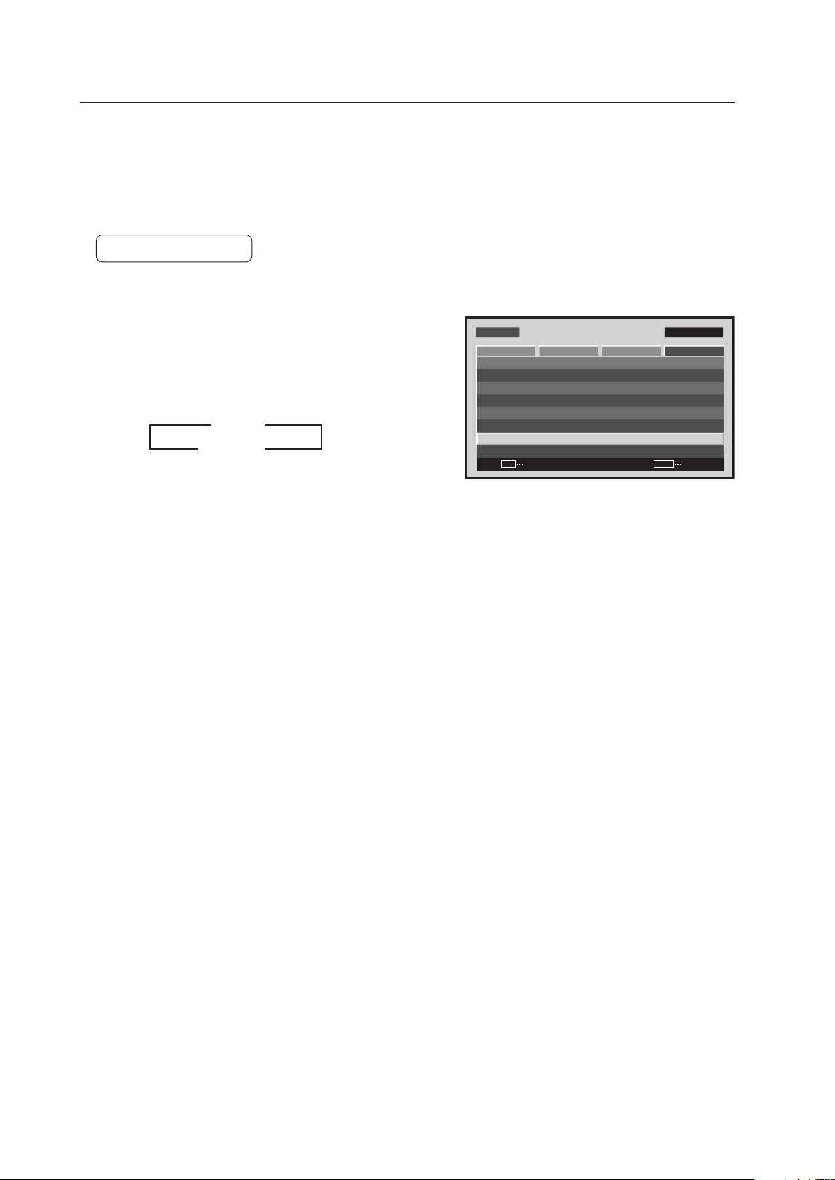
152
Menu Mode
20) Subscreen Mode Setting
During picture-in-picture display, if no subscreen input signal is detected then the black borders of the subscreen are
automatically turned off.
The subscreen mode function is disabled during side-by-side display.
* The lack of a subscreen input signal means there is no video signal or sync signal.
Factory setting: ACTIVE
1 Select ‘OPTION’.
2 Place the cursor on ‘PIP DETECT’ then press the [SET]
button to change the setting.
Each time the [SET] button is pressed, the setting changes
as shown below.
• ACTIVE ...... When no subscreen input signal is input,
no subscreen is displayed. When the
subscreen input is later restored, the
subscreen is displayed again.
• INACTIVE .. When no subscreen signal is input, the
black border is visible.
The ‘PIP DETECT’ setting is common for all inputs.
Screen 2
M E N U IN P U T 1
CHANGE
SET
EXIT
MENU
S C R E E N S E T U P OPTI O N
L A N G U A G E
E N E R G Y S AV E
T I M E R S E T T I N G
S C R E E N M G T.
S P L I T F R E E Z E
A U T O S E T U P M O D E
A U T O F U N C T I O N
P I P D E T E C T
P I C T U R E
: S TA N D A R D
: I N A C T I V E
: O F F
: A C T I V E
: E N G L I S H
: O F F
3 ACTIVE
INACTIVE 2
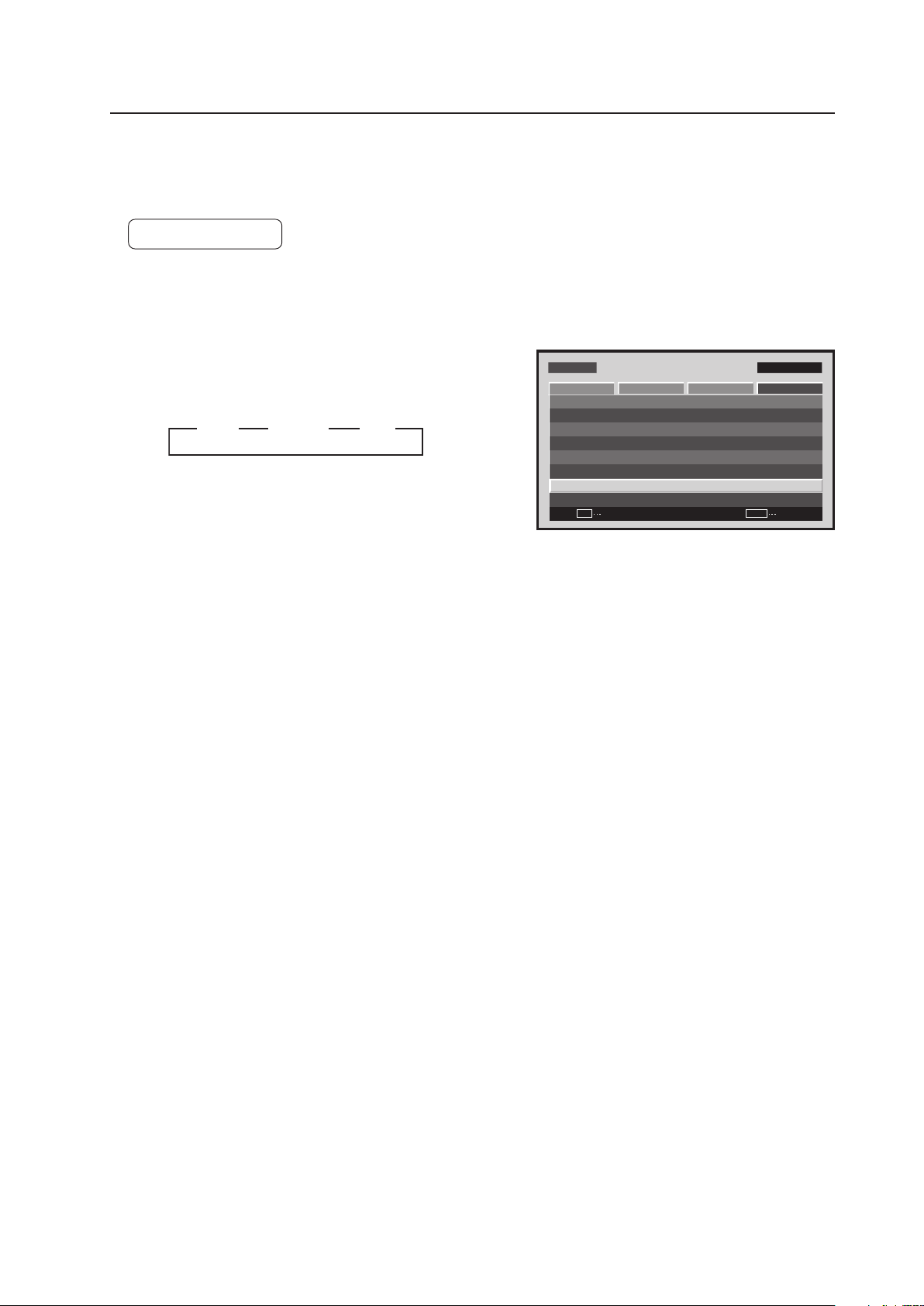
153
Menu Mode
21) PIP DETECT Setting
For setting other than [OFF], the image displayed when the FREEZE button is pressed is displayed in a subscreen as
a freeze-frame image.
Factory setting: OFF
1 Select ‘OPTION’.
2 Place the cursor on ‘SPLIT FREEZE’ then press the [SET]
button to change the setting.
Each time the [SET] button is pressed, the setting changes
as shown below.
• OFF ........... The still picture displayed at the time the
FREEZE button was pressed is displayed
as a single fullscreen image
• S BY S ....... When the FREEZE button is pressed, the
freeze-frame image is displayed in the side-
by-side subscreen
• PIP ............. When the FREEZE button is pressed, the
freeze-frame image is displayed in the
picture-in-picture (left-bottom to left-top)
subscreen.
The ‘SPLIT FREEZE’ setting is common for all inputs.
Screen 2
M E N U IN P U T 1
CHANGE
SET
EXIT
MENU
S C R E E N S E T U P OPTI O N
L A N G U A G E
E N E R G Y S AV E
T I M E R S E T T I N G
S C R E E N M G T.
S P L I T F R E E Z E
A U T O S E T U P M O D E
A U T O F U N C T I O N
P I P D E T E C T
P I C T U R E
: S TA N D A R D
: I N A C T I V E
: O F F
: A C T I V E
: E N G L I S H
: O F F
3 OFF 3 S BY S 3 PIP

154
Integrator Mode
5.4 Integrator Mode
5.4.1 About the Integrator Mode
1) Entering the Integrator Mode
• It is possible to set the integrator mode by the following procedure.
1 Press the [DISPLAY] button to display ‘DISPLAY CALL 1’.
2 When ‘DISPLAY CALL 1’ is displayed, press the [DISPLAY] button again (for 3 seconds or more) to display
‘DISPLAY CALL 2’.
3 It is possible to enter the integrator mode by pressing the [MENU] button when ‘DISPLAY CALL 2’ is displayed.
At this time, press the [MENU] button briefly (the integrator mode cannot be entered if the [MENU] button is held
down for a longer period of time).
2) After entering the integrator mode...
• The adjustment values for COLOR TEMP, DNR, MPEG NR, CTI and PURECINEMA for the PICTURE, SCREEN and
SETUP are all set to their initial values.
The other SETUP and OPTION settings retain their set values.
3) Making adjustment in the integrator mode
• The adjusted values (see section 5.4.3, “Adjustment and Setting in the Integrator Mode 1) to 3)” (pg. 156 to 158))
for PICTURE and SCREEN can be stored in memory for 8 types of input signals (input frequency) for each function.
When a new ninth type of input signal is adjusted, the adjustment data for the oldest input signal is deleted.
• For details, refer to section 5.4.4, “PICTURE, White Balance and SCREEN Position Adjustment Values Memory
Area Tables” (pg. 188).
4) Exiting the integrator mode
• Press the [MENU] button on the remote control or main-control panel to designate to the normal-operation mode.
5) Precautions
(1) In the following cases the integrator mode is automatically cancelled and operation returns to the normal-operation
mode:
• When the input is switched
• When there is no operation for 3 minutes
(2) Adjustment and settings should be performed on the actual video signal to be used or on an adjustment signal
having the same frequency.
(3) The method for entering the integrator mode for PDP-503CMX (pressing the [MENU] button in standby and then
pressing the [POWER] button) is not supported.
(4) Only English is supported in the integrator mode.
(5) During Point Zoom operation or multi-screen display, ‘DISPLAY CALL 2’ is unavailable even if the [DISPLAY]
button is pressed. After disengaging Point Zoom or multi-screen display, follow the instructions under 1) Entering
the Integrator Mode (pg. 113).
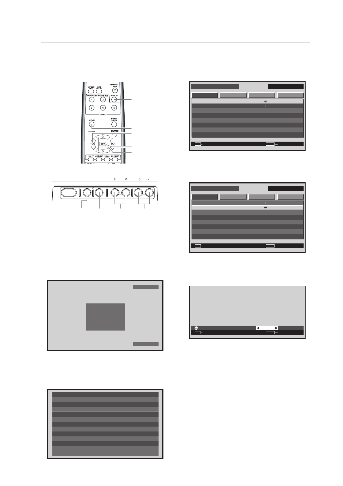
155
Integrator Mode
5.4.2 Example of Integrator Mode Operation
The basic operation in the menu mode is explained using
brightness adjustment as an example.
4 Press the [MENU] button on the remote control
unit or the main-control panel when ‘DISPLAY
CALL 2’ is displayed to open up the integrator
mode screen.
I N T E G R ATO R I N P U T 1
ENTER
S C R E E N S E T U P O P T I O N
C O N T R A S T
B R I G H T N E S S
H . E N H A N C E
V . E N H A N C E
G AMMA
P I C T U R E R E S E T
W H I T E BA L A N C E
C O L O R D E T A I L
PICT U RE
: 1 2 8
: 0
: 0
: 1 2 8
: 2 . 0
SET EXITMENU
5 Press the [5/∞] buttons on the remote control
unit or the main-control panel to select
‘BRIGHTNESS’ then press the [SET] button.
I N T E G R ATO R I N P U T 1
ENTER
S C R E E N S E T U P O P T I O NPICT U RE
SET EXITMENU
: 2 . 0
: 1 2 8
: 0
: 0
: 1 2 8C O N T R A S T
B R I G H T N E S S
H . E N H A N C E
V . E N H A N C E
G AMMA
P I C T U R E R E S E T
W H I T E BA L A N C E
C O L O R D E T A I L
6 Press the [2/3] buttons on the remote control
unit or the main-control panel to adjust to the
desired picture.
B R I G H T N E S S
:
SET
SET EXIT
MENU
0
It is possible to move to other adjustment items
with the 5/∞ buttons.
7 Press the [SET] button on the remote control
unit or the main-control panel.
The adjusted value is saved in memory then
operation returns to the screen in step 5.
To continue with adjusting another item, repeat
steps 5 to 6.
8 When adjustment is complete, press the [MENU]
button on the remote control unit or the main-
control panel button to return to the normal
screen.
* The ID is shown to the side of the input display,
upper right area of the integrator mode screen
(See section 5.5.4, “ID Assigning” (pg. 196)).
STANDBY/ON MENU
DISPLAY
/ SET
– VOL +INPUT SCREEN SIZE
�
2/3MENU DISPLAY
/ SET
5/∞
MENU
5/∞
SET
2/3
DISPLAY
Main-control panel
Remote control unit
1 Set the device to normal operation then press
the [INPUT] button to switch to the input to be
adjusted.
2 Press the [DISPLAY] button on the remote
control unit or the main-control panel to display
‘DISPLAY CALL 1’.
FULL
6 4 0
X
4 8 0
I N P U T 1
F H : 3 1 . 5 k H z
F V : 6 0 . 0 H z
POL. H : N EGA
POL. V : P OSI
3 Press the [DISPLAY] button on the remote
control unit or the main-control panel (3 seconds
or more) when ‘DISPLAY CALL 1’ is displayed to
display ‘DISPLAY CALL 2’.
T E M P E R AT U R E
H O U R M E T E R
O S D
BAU D R AT E
I N F O R M AT I O N
: A B C D E F G H I J K L M N
FA N C O N T R O L
I D N O. S E T
C O L O R M O D E
: + 2 5
: AU T O
: 9 6 0 0 B P S
: O N
: A L L
: N O R M A L
: 0 0 2 3 9 H
DAT E
: 0 0 1 A 0 0 1 X
L OT
: 0 0 1 A 0 0 1 K
S E R I A L N O.
: * * * * * * * * * * * * * * * *
P D P - 4 2 5 C M X / LV C 5
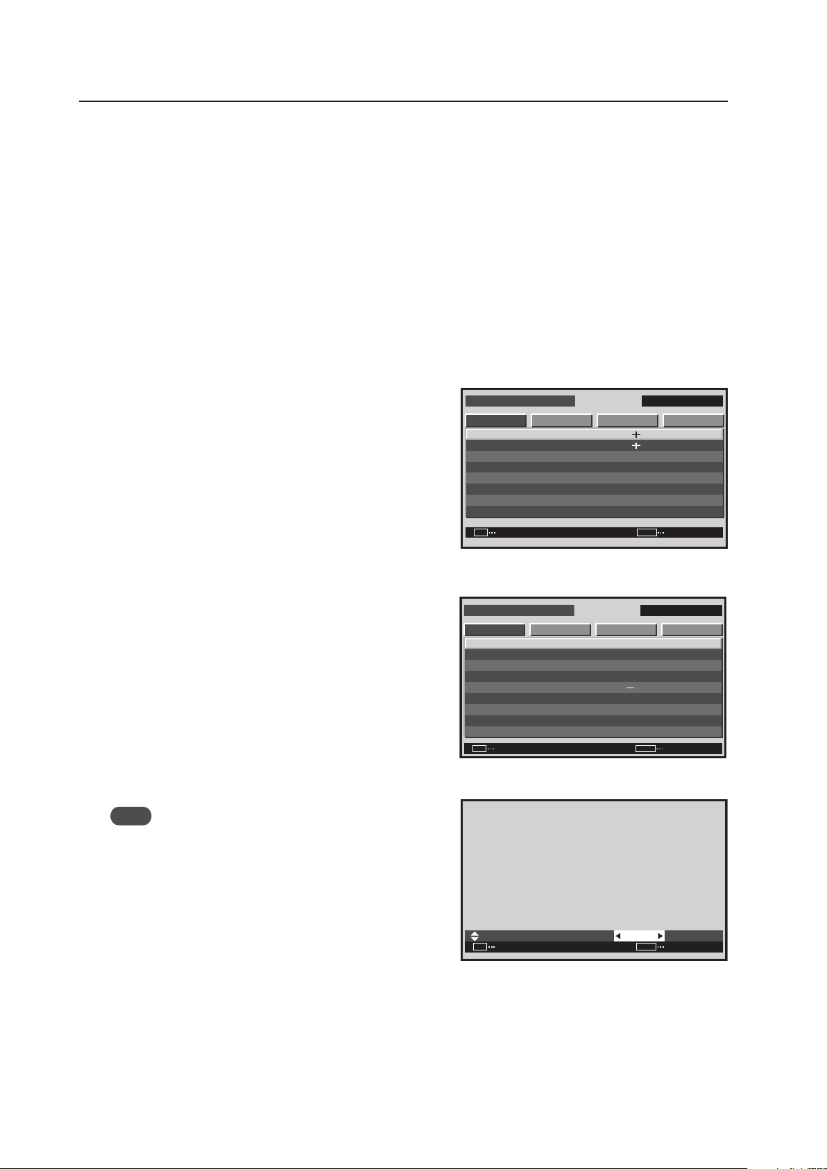
156
Integrator Mode
5.4.3 Adjustment and Setting in the Integrator Mode
For details about button controls, refer to section 5.4.2, “Example of Integrator Mode Operation” (pg. 155).
1) PICTURE Adjustment
The adjustable items shown below are a little different than in the menu mode’s PICTURE adjustment (refer to the
instruction manual).
• PC input
CONTRAST, BRIGHTNESS, H. ENHANCE, V. ENHANCE, etc.
• Video input ★ (Applicable only when a PDA-5003 or PDA-5004 is installed.)
CONTRAST, BRIGHTNESS, COLOR, TINT, SHARPNESS, etc.
For details, refer to section 5.1.4, “List of Adjustable and Settable Items” (pg. 103).
1 After switching to the input (INPUT1 to INPUT5) to be
adjusted, enter the integrator mode.
Select ‘PICTURE’.
2 Perform adjustment.
Note
When there is PC signal input at INPUT1, 2, and 5,
‘COLOR’, ‘TINT’ and ‘SHARPNESS’ are unavailable.
When there is video input, ‘H. ENHANCE’ and ‘V.
ENHANCE’ are unavailable.
Use the [5/∞] buttons on the remote control or the main-
control panel.
Perform adjustment using the [2/3] buttons on the remote
control or the main-control panel to change settings.
It is possible to move to another item for adjustment using
the [5/∞] buttons.
The value adjusted here becomes the center value for adjustment in the menu mode.
Press the [SET] button to return to screen 1-
1 or screen 2-2.
For details about the adjustable range, refer to section 5.1.4, “List of Adjustable and Settable Items” (pg. 103).
I N T E G R ATO R I N P U T 1
ENTER
S C R E E N S E T U P OP T I O NPICTURE
SET
EXIT
MENU
: 2 . 0
: 1 2 8
: 0
: 0
: 1 2 8C O N T R A S T
B R I G H T N E S S
H . E N H A N C E
V . E N H A N C E
G AMMA
P I C T U R E R E S E T
W H I T E B A L A N C E
C O L O R D E T A I L
Screen 1-1
For PC signal input
For video signal input
(Applicable only when a PDA-5003/PDA-5004 is installed.)
I N T E G R ATO R I N P U T 1
ENTER
S C R E E N S E T U P OP T I O N
C O N T R A S T
T I N T
S H A R P N E S S
PICTURE
0
:
0
:
0
:
2 3
:
:
0
:
SET
EXIT
MENU
B R I G H T N E S S
G AMMA
P I C T UR E R E S E T
WH I T E B A L A N C E
C O L O R D E T A I L
C O L O R
2 . 0
:
SET
SET EXIT
MENU
0
B R I G H T N E S S
Screen 2
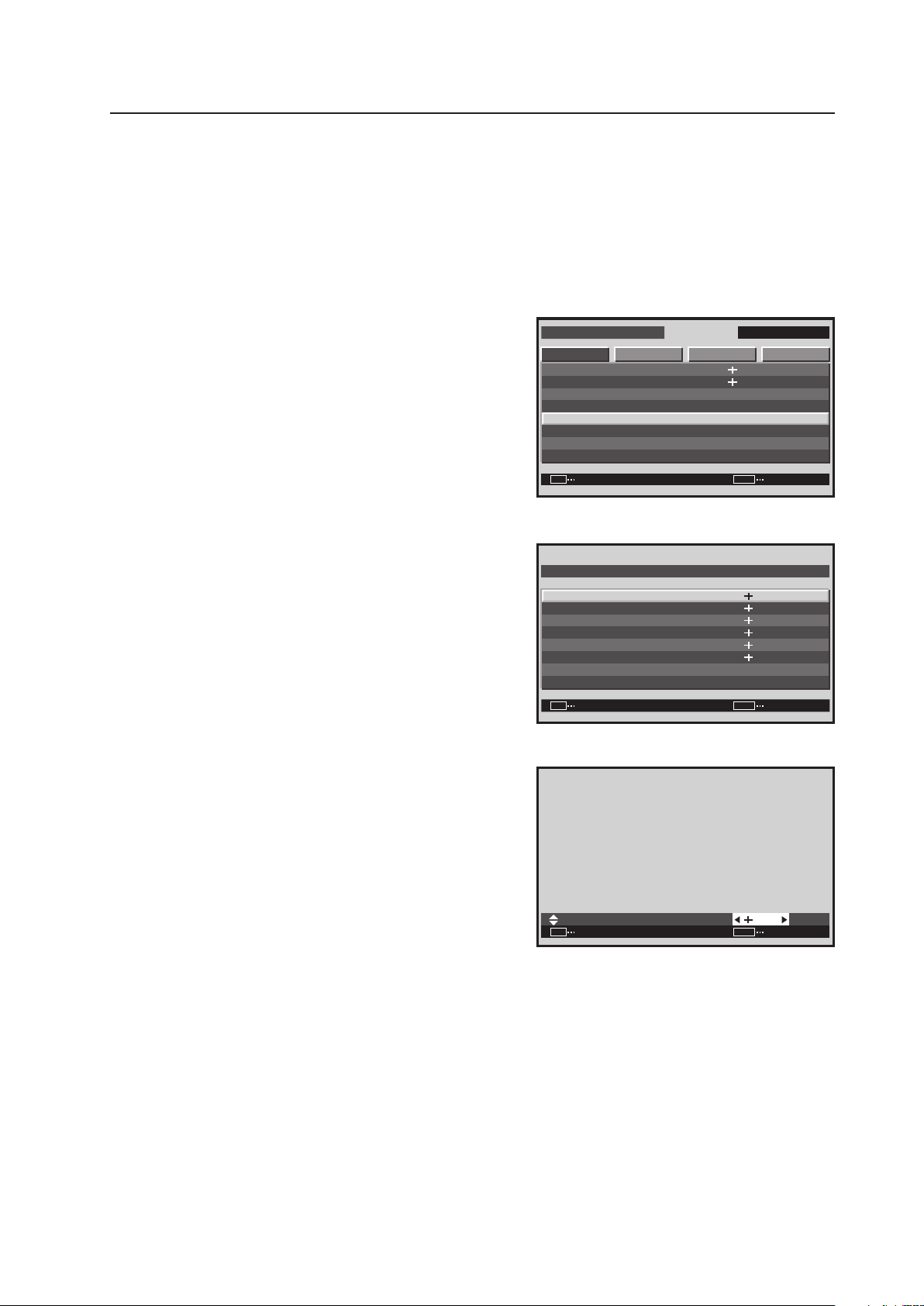
157
Integrator Mode
2) WHITE BALANCE Adjustment
The adjustable items are R. HIGH, G. HIGH, B. HIGH, R. LOW, G. LOW and B. LOW.
1 Enter the integrator mode.
(Refer to section 5.4.1, “About the Integrator Mode” (pg. 154).)
Select ‘PICTURE’.
2 Place the cursor on ‘WHITE BALANCE’ then press the
[SET] button.
3 Use the [5/∞] buttons to switch between items.
In screen 3, when ‘YES’ is selected for ‘WHITE BAL.
RESET’, all of the WHITE BALANCE adjustment values
return to the factory settings.
4 Use the [2/3] buttons to change a setting.
It is possible to move to another item for adjustment using
the [5/∞] buttons.
Press the [SET] button to return to screen 2.
<Adjustable range> Each item: 0 to 255
I N T E G R ATO R I N P U T 1
ENTER
S C R E E N S E T U P OP T I O NPICTURE
SET EXITMENU
: 2 . 0
: 1 2 8
: 0
: 0
: 1 2 8C O N T RA S T
B R I G H T N E S S
H . E N H A N C E
V . E N H A N C E
G AMMA
P I C T U R E R E S E T
W H I T E B A L A N C E
C O L O R D E T A I L
Screen 1
ENTER
R . H I G H
G . H I G H
B . H I G H
R . L OW
W H I T E BA L . R E S E T
R E T URN
G . L OW
W H I T E B A L A N C E
B . L OW
:
SET EXITMENU
1 2 8
:
1 2 8
:
1 2 8
:
1 2 8
:
1 2 8
:
1 2 8
Screen 3
Screen 3
:
SET SET EXITMENU
1 2 8
R . H I G H
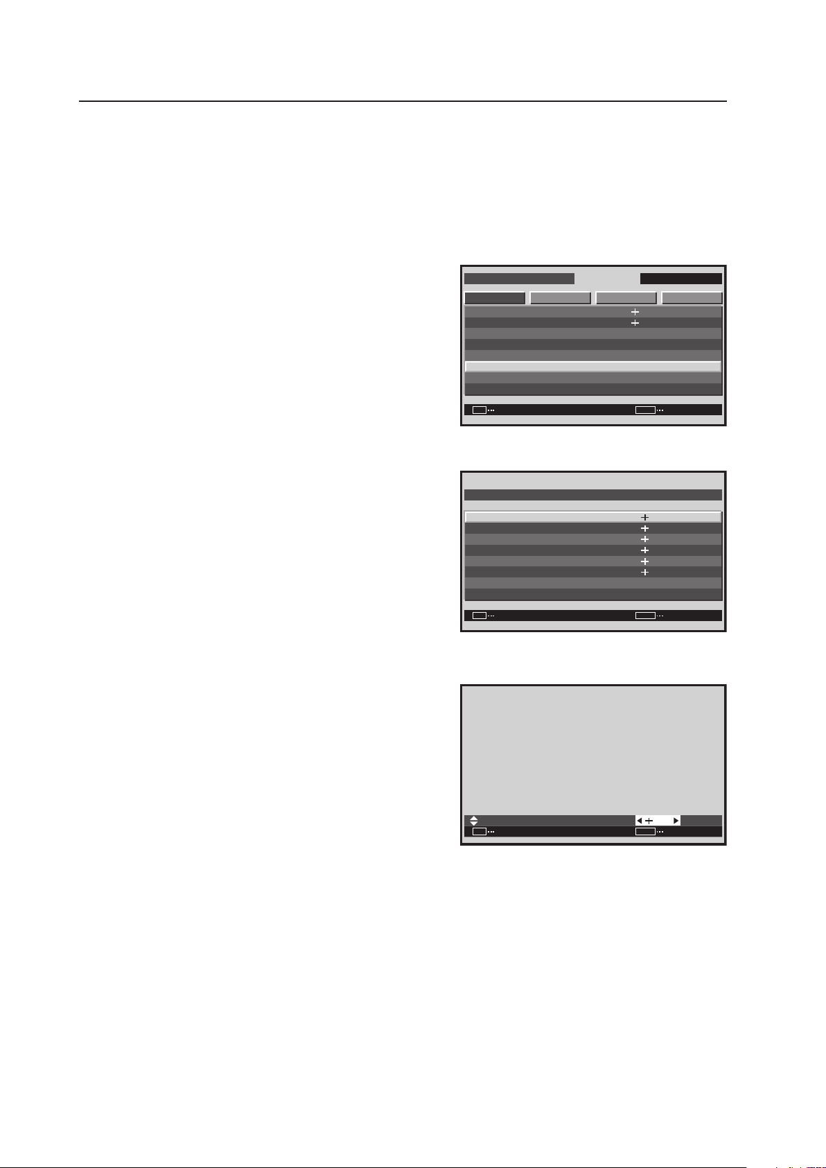
158
Integrator Mode
3) COLOR DETAIL setting
1 Enter the integrator mode.
(Refer to section 5.4.1, “About the Integrator Mode” (pg. 154).)
2 Select ‘PICTURE’.
3 Place the cursor on ‘COLOR DETAIL’ then press the [SET]
button.
4 Use the [5/∞] buttons to switch between items.
5 Adjustment is performed using the [2/3] buttons.
C. DETAIL can be adjusted for each color.
• C. DETAIL RED: The + side approaches magenta, and
the – side approaches yellow.
• C. DETAIL YELLOW: The + side approaches red, and
the – side approaches green.
• C. DETAIL GREEN: The + side approaches yellow, and
the – side approaches cyan.
• C. DETAIL CYAN: The + side approaches green, and
the – side approaches blue.
• C. DETAIL BLUE: The + side approaches cyan, and the
– side approaches magenta.
• C. DETAIL MAGENTA: The + side approaches blue, and
the – side approaches red.
It is possible to move to another item for adjustment using
the [5/∞] buttons.
Press the [SET] button to return to screen 3.
Screen 3
I N T E G R ATO R I N P U T 1
ENTER
S C R E E N S E T U P OP T I O NPICTURE
: 1 2 8
: 0
: 0
: 1 2 8
SET
EXIT
MENU
: 2.0
C O N T R A S T
B R I G H T N E S S
H . E N H A N C E
V . E N H A N C E
G AMMA
P I C T U R E R E S E T
W H I T E B A L A N C E
C O L O R D E T A I L
Screen 4
ENTER
R E D
Y E L L OW
G R E E N
C Y A N
C . D E T A I L R E S E T
R E T U RN
B L U E
C O L O R D E TA I L
M AG EN T A
:
:
:
:
:
:
SET
EXIT
MENU
3 0
3 0
3 0
3 0
3 0
3 0
Screen 5
:
SET
SET EXIT
MENU
2 9
R E D
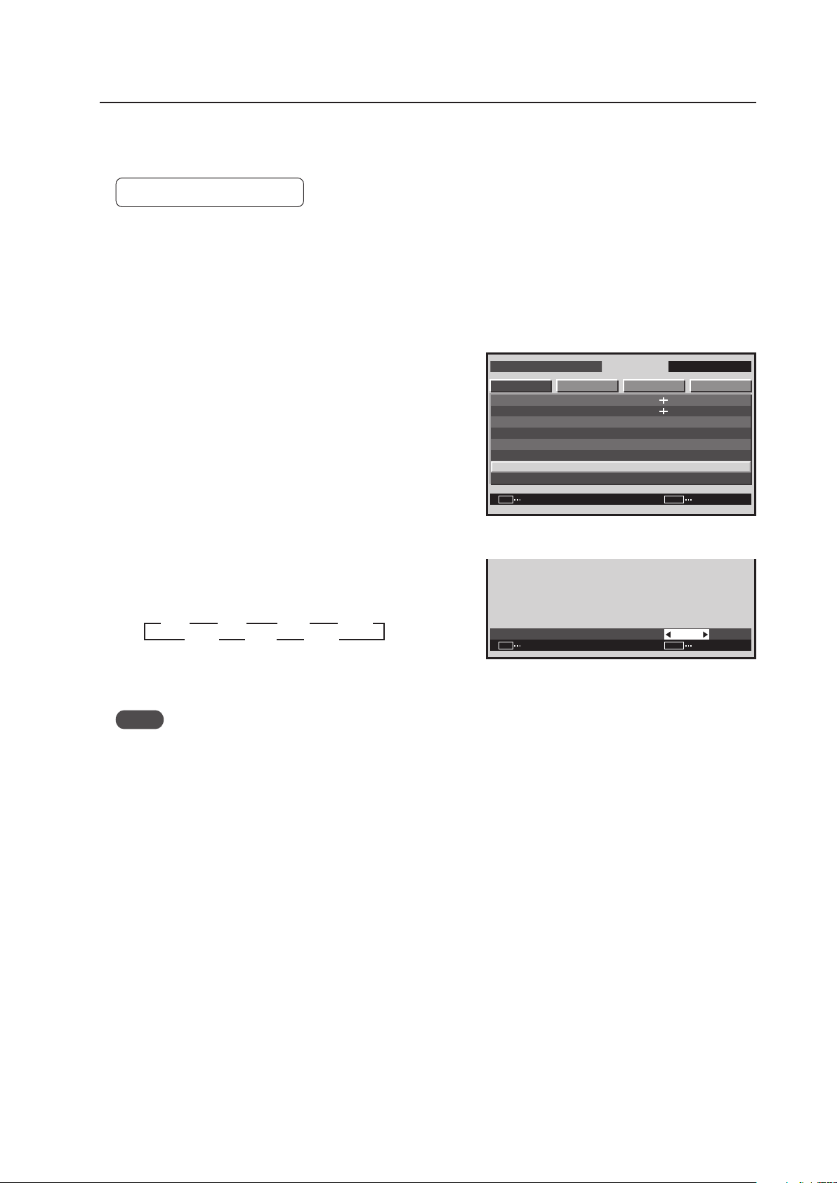
159
Integrator Mode
4) GAMMA Setting
This function sets the GAMMA characteristics for the video.
Factory setting: GAMMA 2.2
1 Enter the integrator mode.
(Refer to section 5.4.1, “About the Integrator Mode” (pg. 154).)
2 Select ‘PICTURE’.
3 Place the cursor on ‘GAMMA’ then press the [SET] button.
4 Press the [2/3] buttons to change the setting.
Each time a [2/3] button is pressed, the setting changes
as shown below.
Press the [SET] button to return to screen 3.
Notes
• The GAMMA value is set based on Pioneer’s measurement standards.
• After adjusting the WHITE BALANCE, the WHITE BALANCE is not lost even when the GAMMA setting is changed.
I N T E G R ATO R I N P U T 1
ENTER
S C R E E N S E T U P OP T I O N
C O N T R A S T
PICTURE
: 1 2 8
: 0
: 0
: 1 2 8
SET EXITMENU
: 2.0
B R I G H T N E S S
H . E N H A N C E
V . E N H A N C E
GAMMA
P I C T UR E R E S E T
W H I T E BA L A N C E
C O L O R D E T A I L
Screen 3
G A M M A
:
SET SET EXITMENU
2.0
Screen 4
3
1.8
2.2
2.3
2.4
22 2
1.9 2.0 2.1
3
3 3
2 2 2 2
3 3 3
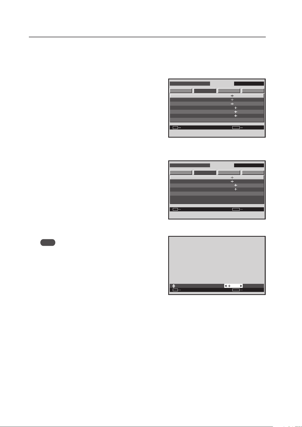
160
Integrator Mode
5) SCREEN (Screen Position) Adjustment
The adjustable items are H. POSITION, V. POSITION, CLOCK, PHASE, H. SIZE and V. SIZE.
1 Enter the integrator mode then switch to the input
(INPUT1 to INPUT5) to be adjusted.
2 Select ‘SCREEN’ then select the item to adjust.
In screen 2, when ‘YES’ is selected for the ‘SCREEN
RESET’, all SCREEN values return to the factory settings.
3 Perform the adjustment.
Note
‘CLOCK’ and ‘PHASE’ can be adjusted when there is PC
signal input.
Use the [5/∞] buttons on the remote control or the main-
control panel to select a different item.
Use the [2/3] buttons on the remote control or the main-
control panel to change settings.
The values adjusted here become the menu mode’s initial
values.
Press the [SET] button to return to screen 2.
<Adjustable Range>
H. POSITION, V. POSITION when there is PC signal input: 0 to 255 (initial value: 128)
H. POSITION, V. POSITION when there is video signal input: 0 to 127 (initial value: 64) (When a PDA-5003/PDA-
5004 is used.)
H. SIZE, V. SIZE: 0 to 63 (initial value: 0)
CLOCK: 0 to 255 (initial value: 128)
PHASE: 0 to 31 (initial value: 16)
<Adjustment Order>
Performing adjustment in the following order is effective.
V. POSITION H. POSITION CLOCK H. POSITION CLOCK PHASE
I N T E G R ATO R I N P U T 1
ENTER
S C R E E N S E T U P OP T I O N
H . P O S I T O I N
V . P O S I TO I N
C L O C K
P H A S E
S C R E E N R E S E T
H . S I Z E
V . S I Z E
PICTURE
: 1 2 8
: 1 6
: 3 2
: 3 2
: 1 2 8
SET
EXIT
MENU
: 1 2 8
Screen 2
For PC signal input
:
SET
SET EXIT
MENU
1 2 8
H . P O S I T I O N
Screen 3
I N T E G R ATO R I N P U T 1
ENTER
S C R E E N S E T U P OP T I O N
H . P O S I T O I N
V . P O S I TO I N
S C R E E N R E S E T
H . S I Z E
V . S I Z E
PICTURE
: 3 2
: 3 2
: 1 2 8
SET
EXIT
MENU
: 1 2 8
For video signal input
(Applicable only when a PDA-5003/PDA-5004 is
installed.)
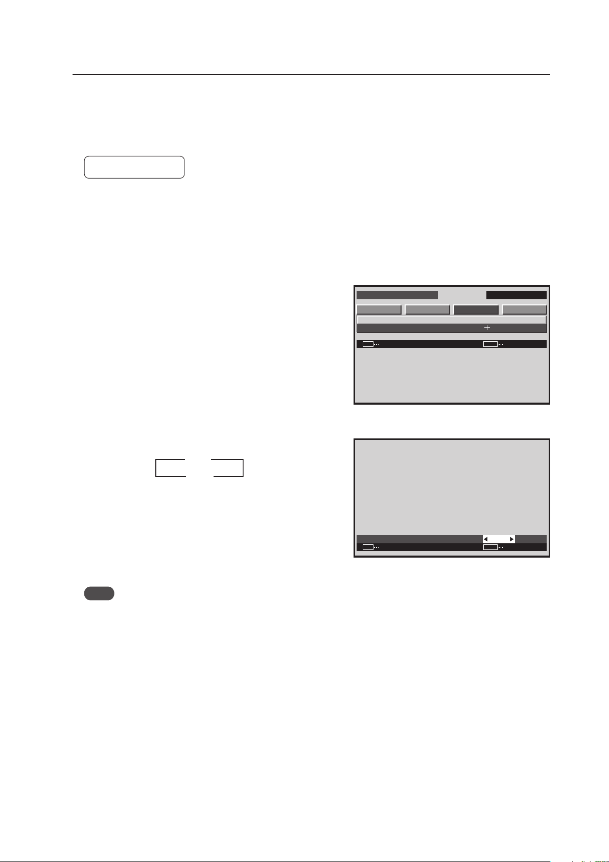
161
Integrator Mode
6) Brightness Enhancement (BRT. ENHANCE) Setting at the Center of the Screen
This function improves and enhances the brightness of the center of the screen.
• When emphasizing the brightness of the screen: Set to ON.
• When emphasizing uniformity of the screen: Set to OFF.
Factory setting: OFF
1 Enter the integrator mode.
(Refer to section 5.4.1, “About the Integrator Mode” (pg. 154).)
2 Select ‘SET UP’.
3 Place the cursor on ‘BRT. ENHANCE’ then press the [SET]
button.
4 Each time a [2/3] button is pressed, the setting changes
as shown below.
Perform the BRT. ENHANCE setting for each input
(INPUT1 to INPUT5).
Also, perform the setting for both PC and video signals.
After setting is complete, press the [SET] button to return
to screen 3.
Note
During video wall, the BRT. ENHANCE function is unavailable,
however, settings can still be changed.
I N T E G R ATO R I N P U T 1
ENTER
S C R E E N S E T U P OP T I O N
B R T. E N H A N C E
S U B VO L U M E
PICTURE
SET EXITMENU
:
:
O F F
2 0
Screen 3
B R T. E N H A N C E
:
SET SET EXITMENU
O F F
Screen 4
3
3
ON
OFF 2
2
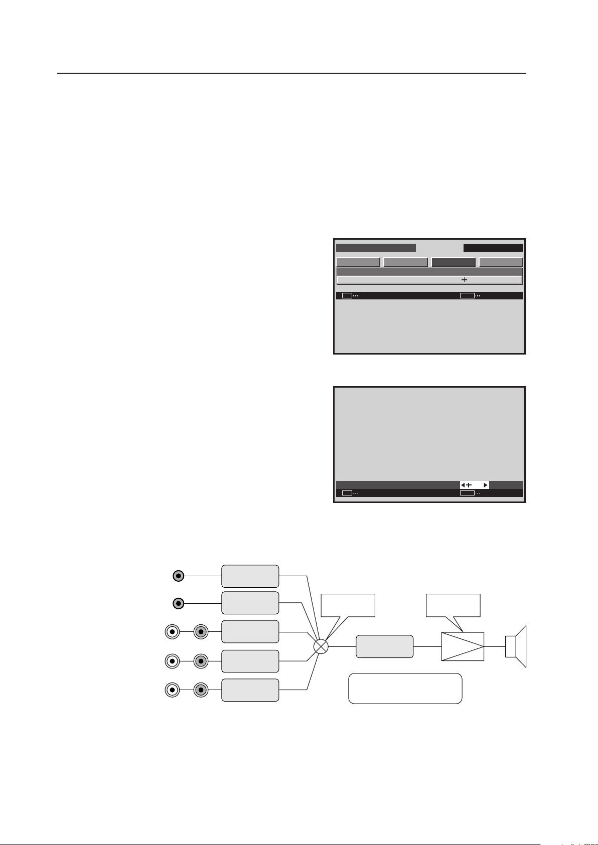
162
Integrator Mode
1 AUDIO INPUT
(INPUT1)
Stereo mini jack
2 AUDIO INPUT
(INPUT2)
Stereo mini jack
3 AUDIO INPUT
(INPUT3/4)
★1
(INPUT3)
★2
Pin jack
4 AUDIO INPUT
(INPUT4)
★2
Pin jack
5 AUDIO INPUT
(INPUT5)
★
Pin jack
INPUT1
SUB VOLUME
INPUT2
SUB VOLUME
INPUT3
SUB VOLUME
INPUT4
SUB VOLUME
INPUT5
SUB VOLUME
INPUT
SELECTOR
POWER
AMPLIFIER
VOLUME
★ : Applicable only when a PDA-5003/PDA-5004 is installed.
★1: Applicable only when a PDA-5003 is installed.
★2: Applicable only when a PDA-5004 is installed.
Audio block diagram
(concept diagram)
7) SUB VOLUME Setting
This item is for adjusting the audio input level for each input.
This is useful when adjusting the level between different sources, for example a DVD player and a PC.
After muting the audio before hand, enter the integrator mode and perform the adjustment.
1 Enter the integrator mode.
(Refer to section 5.4.1, “About the Integrator Mode” (pg. 154).)
2 Select ‘SET UP’.
3 Place the cursor on ‘SUB VOLUME’ then press the [SET]
button.
4 Perform the adjustment.
Use the [2/3] buttons on the remote control or the main-
control panel to change settings.
Press the [SET] button to return to screen 3.
<Adjustable Range>
Each item: 0 to 20 (initial value: 20)
<Adjustment Order>
Performing adjustment in the following order is effective.
1. VOLUME (normal-operation mode): Raise the volume to the actual operating condition.
2. SUB VOLUME (integrator mode): Adjust the input with high volume to match the input with low volume.
I N T E G R ATO R I N P U T 1
ENTER
S C R E E N S E T U P OP T I O N
B R T. E N H A N C E
S U B VO L U M E
PICTURE
:
SET
EXIT
MENU
:
O F F
2 0
Screen 3
S U B VO L U M E
:
SET
SET EXIT
MENU
2 0
Screen 4
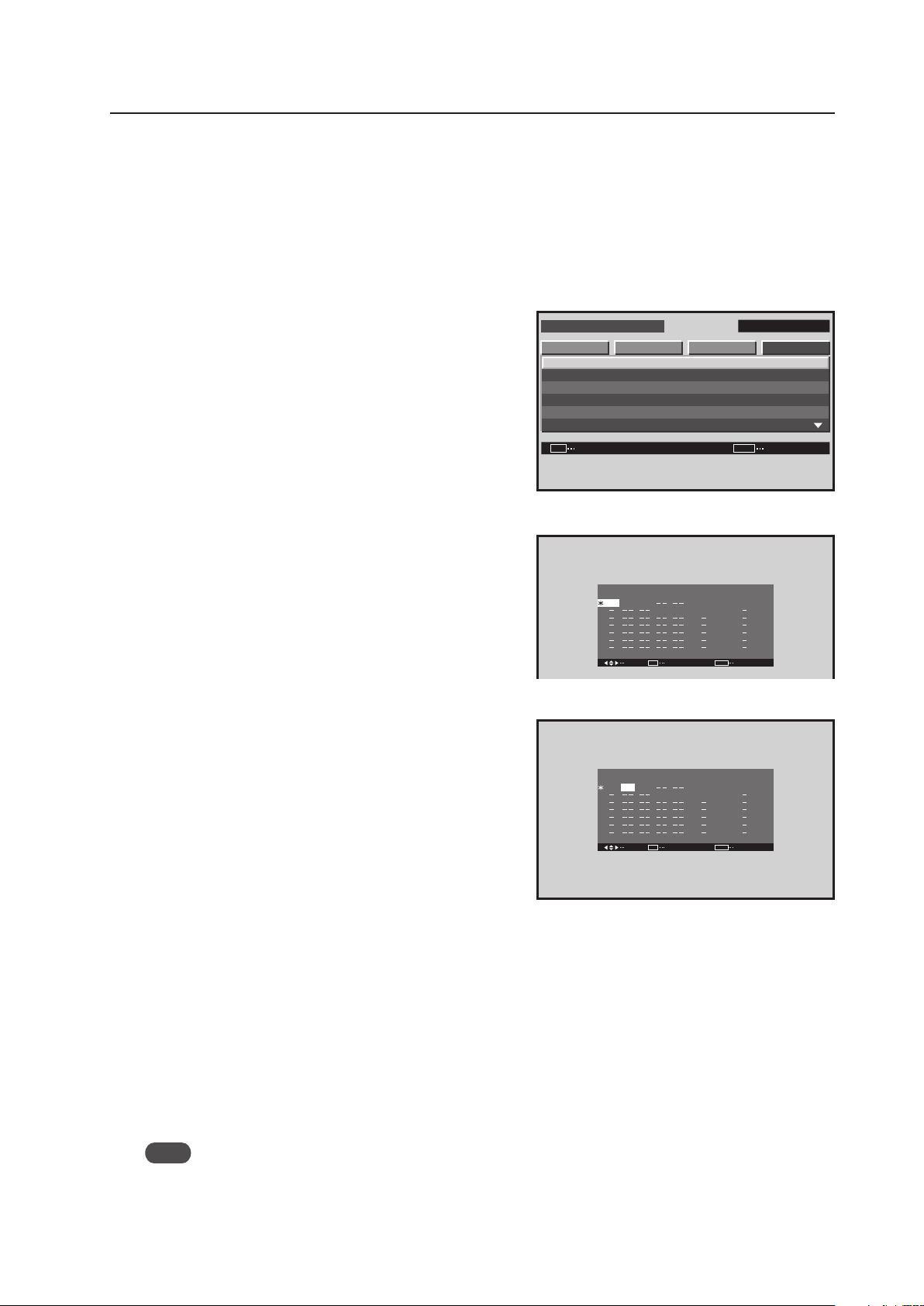
163
Integrator Mode
I N T E G R ATO R I N P U T 1
ENTER
S C R E E N S E T U P OP T I O N
P R OG R A M T I M E R
S C R E E N M A S K
S I D E M A S K
V I D E O WA L L
BAU D R A T E
I D N O . SE T
PICTURE
:
:
:
SET EXITMENU
G R E E N
0 1 H
3 8 4 0 0 B P S
8) Program Timer Setting
This option can set the day of the week, time, input, and function desired when the power is turned ON/OFF.
1 Enter the integrator mode.
(Refer to section 5.4.1, “About the Integrator Mode” (pg. 154).)
2 Select ‘OPTION’.
3 Place the cursor on ‘PROGRAM TIMER’ then press the
[SET] button.
4 Select the item to be set with the [5/∞/2/3] buttons
then press the [SET] button.
5 Change the setting with the [5/∞/2/3] buttons then press
the SET button.
7 Program timer settings
DATE ........... Sets the day of the week the program timer
will be executed. It can be set as “every
day” or as “every Friday”
ON ............... Sets the power ON time
OFF ............. Sets the power OFF time
INPUT .......... Sets the input when the power is turned on.
FUNCTION .. Sets the function that will be executed when
the power is turned ON
7 To reset the program;
Press the CLEAR button with the cursor on DATE. This resets the program.
7 To clear the set contents;
Press the CLEAR button with the cursor on ON, OFF, INPUT, FUNCTION. This clears the item’s contents.
7 Viewing the program timer screen
• “∗” in the DATE column
This indicates “every”. When there is only “∗” in the DATE column, it means “every day”, while “*FRI” means
“every Friday”.
• ON, OFF column “–“
The hour and minute must be set for this option to function.
• INPUT, FUNCTION column “–“
It displays the “last” (state when the power is off) setting.
Note
The set time may slow by approximately 1 minute per month.
The ‘PROGRAM TIMER’ setting is common for all inputs.
When the program timer power has been turned ON, “POWER ON MODE“ is unavailable.
Screen 3
SEL. ADJ
P R OGR AM T I M E R
DAT E
R E T U R N
F R I
EXIT
MENU
O N
:
:
:
:
:
:
:
O F F I N P U T
I N P U T 4
I N P U T 1
F U N C T I O N
I NV E R S E
0 00 0
2 3
:
0 0
:
SET
Screen 4
Screen 5
SEL. ADJ
P R OGR AM T I M E R
DAT E
R E T U R N
F R I
EXIT
MENU
O N
:
:
:
:
:
:
:
O F F I N P U T
I N P U T 4
I N P U T 1
F U N C T I O N
I NV E R S E
0 0
2 3
:
0 0
:
:
:
:
:
:
SET
0 0
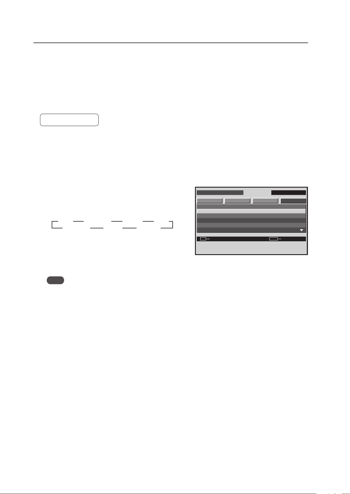
164
Integrator Mode
9) SCREEN MASK Setting
This function displays the inverse of the normal picture on the entire screen, or displays a single color such as white,
red, green or yellow according to an internal signal in the Plasma Display.
When setting something other than ‘OFF’ or ‘INVERSE’ it is not possible to display a signal input.
When the screen has been burned, this function may be used as an emergency measure for relieving the problem (It
is not possible to completely remove the burning).
For details, refer to section 5.6, “Screen Burning” (pg. 211).
Factory setting: OFF
1 Enter the integrator mode.
(Refer to section 5.4.1, “About the Integrator Mode” (pg. 154).)
2 Select ‘OPTION’.
3 Place the cursor on ‘SCREEN MASK’ then press the [SET]
button to change the setting.
Each time the [SET] button is pressed, the setting changes
as shown below.
OFF: The normal display appears.
INVERSE: The RGB levels of the display are reversed with
respect to the normal display.
WHITE, RED, GREEN, BLUE, YELLOW: Only the selected color is displayed.
Note
In a mode other than OFF, operation is performed after the OSD display ends.
The ‘SCREEN MASK’ setting is common for all inputs.
I N T E G R ATO R I N P U T 1
CHANGE
S C R E E N S E T U P OP T I O NPICTURE
SET
EXIT
MENU
P R OG R A M T I M E R
S C R E E N M A S K
S I D E M A S K
V I D E O WA L L
BAU D R A T E
I D N O . SE T
:
:
:
G R E E N
0 1 H
3 8 4 0 0 B P S
Screen 3
WHITE
INVERSE
OFF
3 3
RED
GREEN
BLUE
3
YELLOW
3
222
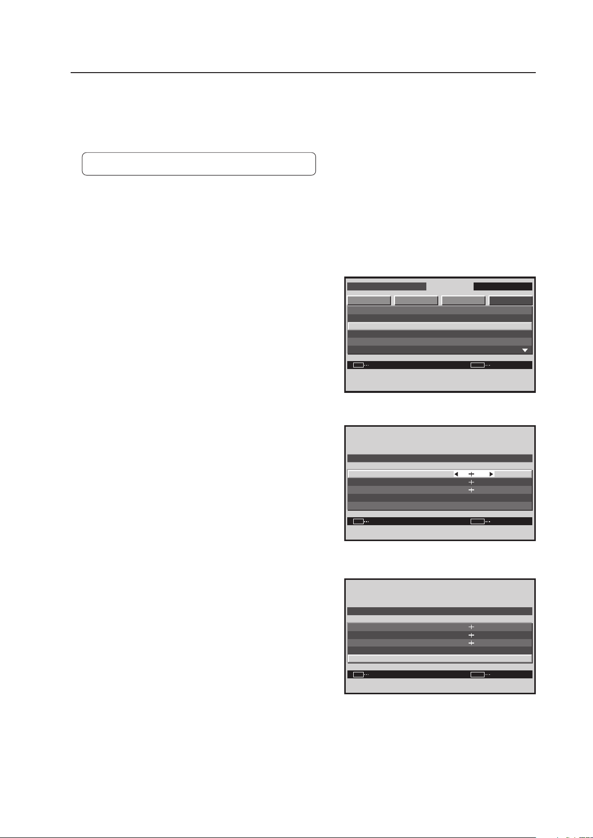
165
Integrator Mode
S I D E M A S K
8 0
8 0
8 0
SET
R . L E V E L
G . L E V E L
B . L E V E L
D E FAU LT
:
:
:
SET EXITMENU
Screen 5
10) SIDE MASK Setting
This mode is for adjusting the brightness of the no-image section around the screen when the screen size is ‘4:3’ etc.
When performing adjustments, pay attention to the brightness balance between the displayed signal and that of the
adjacent sets.
Factory setting: R. LEVEL, G. LEVEL, B. LEVEL ...... 80
1 Enter the integrator mode.
(Refer to section 5.4.1, “About the Integrator Mode” (pg. 154).)
2 Select ‘OPTION’.
3 Place the cursor on ‘SIDE MASK’ then press the [SET]
button.
4 Place the cursor on a level (R. LEVEL, G. LEVEL, B. LEVEL)
then adjust the setting using the [2/3] buttons.
<Adjustable Range>
Each item: 0 to 255 (initial value: 80)
5 Place the cursor on ‘DEFAULT’ then press the [SET] button
to return to the factory setting.
The ‘SIDE MASK’ settings are common for all inputs.
I N T E G R ATO R I N P U T 1
ENTER
S C R E E N S E T U P OP T I O NPICTURE
SET EXITMENU
P R OG R A M T I M E R
S C R E E N M A S K
S I D E M A S K
V I D E O WA L L
BAU D R A T E
I D N O . SE T
:
:
:
G R E E N
0 1 H
3 8 4 0 0 B P S
Screen 3
S I D E M A S K
8 0
8 0
8 0
SET
R . L E V E L
G . L E V E L
B . L E V E L
D E FAU LT
:
:
:
SET
EXIT
MENU
Screen 4
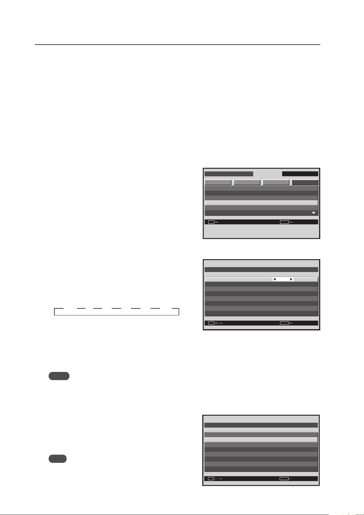
166
Integrator Mode
11) VIDEO WALL Setting
Use this feature to configure a 4-panel to 25-panel video wall.
[Setting Method]
7 Setting the ID NO. SET
Refer to “13) Assigning an ID“ (pg. 171)
7 Setting the screen divider
1 Enter the integrator mode.
(Refer to section 5.4.1, “About the Integrator Mode” (pg. 154).)
2 Select ‘OPTION’.
3 Place the cursor on ‘VIDEO WALL’ then press the [SET]
button.
4 Place the cursor on ‘DIVIDER’.
5 Press the [2/3] buttons then press the [SET] button to
change the settings.
Each time the [2/3] buttons are pressed, the setting
changes as shown below.
OFF, 1 ..... Screen division is not performed.
4 .............. 4-panel video wall
9 .............. 9-panel video wall
16 ............ 16-panel video wall
25 ............ 25-panel video wall
Notes
• When 4 to 25 screens have been selected, set POSITION.
• When a problem occurs while programming the video wall settings, externally power down the video wall panels.
7 Setting the position
The POSITION is where a particular panel resides in the video
wall.
6 Place the cursor on ‘POSITION’ then press the [SET]
button.
Note
Set ‘DIVIDER‘ at other than ‘OFF‘ and ‘1‘.
Screen 3
I N T E G R ATO R I N P U T 1
ENTER
S C R E E N S E T U P OP T I O NPICTURE
SET
EXIT
MENU
P R OG R A M T I M E R
S C R E E N M A S K
S I D E M A S K
V I D E O WA L L
BAU D R A T E
I D N O . SE T
:
:
:
G R E E N
0 1 H
3 8 4 0 0 B P S
Screen 4, 5
V I D E O WA L L
N O R M A L
O F F
O F F
:
:
:
O F F
:
SET
EXIT
MENU
D I V I DE R
P O S I T I ON
T Y P E
AU T O I D
P . O N DE L AY
A B L L I N K
R E P E A T T I M E R
R E T U R N
3 13 OFF 3 4 3 9 3 16 3
25
33333 3
Screen 6
V I D E O WA L L
N O R M A L
O F F
O F F
D I V I DE R
T Y P E
AU T O I D
P . O N DE L AY
A B L L I N K
R E P E A T T I M E R
R E T U R N
:
:
:
O F F
:
SET EXITMENU
P O S I T I ON
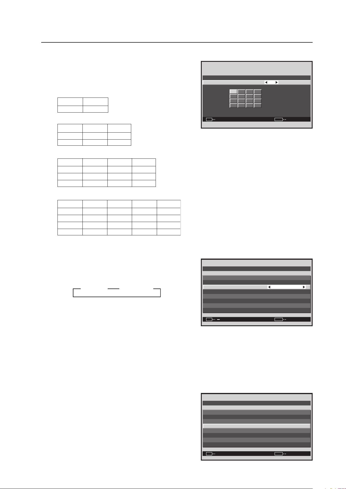
167
Integrator Mode
7 Use the [2/3] buttons to change the settings.
[Setting the POSITION]
•When the screen is divided, the Video Wall option is
unavailable.
•ID positions for 4 panels
•ID positions for 9 panels
•ID positions for 16 panels
•ID positions for 25 panels
7 Setting the display mode
8 Place the cursor on ‘TYPE’ then press the [2/3] buttons
to change the settings.
Each time a [2/3] button is pressed, the setting changes
as shown below.
NORMAL ..... It expands the video image without
correcting the displacement of the part
where the displays are combined.
ADJUSTED ... It expands the video image by correcting
the displacement of the part where the
displays are combined.
7 Setting AUTO ID
When ‘ON‘ is set, the ID for each of the multiple displays
linked by the remote control cable is set automatically.
9 Place the cursor on ‘AUTO ID’ then press the [SET] button.
Screen 7
V I D EO WAL L POS I T I O N
1 6
POS I T IO N N O.
:
SET
EXITSET
MENU
NO.1 NO.2
NO.3 NO.4
NO.1 NO.2 NO.
NO.4 NO.5
NO.2
NO.6
NO.6
NO.7
NO.1
NO.5
NO.9
NO.8 NO.9
NO.3
NO.7
NO.4
NO.8
NO.2
NO.7
NO.1
NO.6
NO.3
NO.8
NO.4
NO.9
NO.5
NO.10
3
NO.10 NO.11 NO.12
NO.13 NO.14 NO.15 NO.16
NO.11 NO.12 NO.13 NO.14 NO.15
NO.16 NO.17 NO.18 NO.19 NO.20
NO.21 NO.22 NO.23 NO.24 NO.25
Screen 8
V I D E O WAL L
N O R M A L
O F F
O F F
:
:
:
O F F
:
SET
EXIT
MENU
D I V I DE R
T Y P E
AU T O I D
P . O N DE L AY
A B L L I N K
R E P E A T T I M E R
R E T U R N
P O S I T I ON
3 NORMAL 3
33
ADJUSTED
Screen 9
V I D E O WAL L
N O R M A L
2 5
:
:
O F F
:
SET
EXITENTER
MENU
D I V I DE R
P O S I T I ON
T Y P E
AU T O I D
P . O N DE L AY
R E T U R N
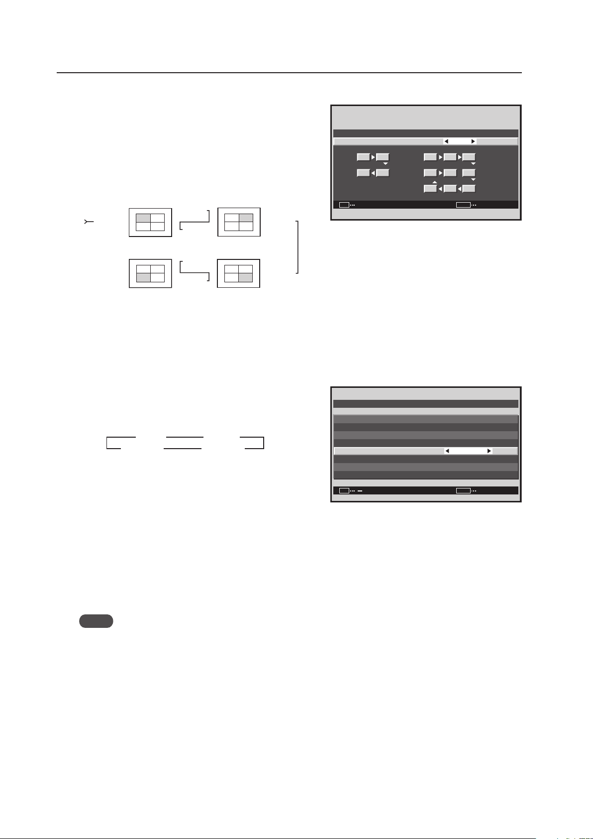
168
Integrator Mode
0 Press the [2/3] buttons to change the settings.
- Press the [SET] button.
[Setting the AUTO ID]
ON ....... The AUTO ID function operates
In the case of the 4-screen configuration, shown below,
Display1 = ID1 and Display 4 = ID4.
Auto ID is only available for 4-screen/9-screen Video Walls.
OFF ..... The AUTO ID function does not operate.
7 Setting the POWER ON DELAY
This option sets the power ON timing for the panels that
make up a video wall to avoid a power surge.
= Place the cursor on ‘P.ON DELAY’ and press the [2/3]
buttons to change the settings.
Each time a [2/3] button is pressed, the setting changes
as shown below.
[Setting the POWER ON DELAY]
(When 1, 4, and 9 screen Video Walls)
ON ........... When the power is turned on, the power of
each is turned on at slightly different times.
OFF ......... When the power is turned on, the power of all
the displays turns on at the same time.
(When 16 and 25 screen Video Walls)
MODE1 ... When the power is turned on, after a delay, each panel turns on.
MODE2 ... When the power is turned on, after a longer delay, each panel turns on.
Notes
• This function is effective when the AUTO ID setting is ‘ON’ with 4 or 9 screens. Set the AUTO ID in advance.
• After setting this function, turning on the power to the first display causes the other units to turn on in succession.
• From the second display, it is not possible to turn on the power using the remote control or control panel. To
forcibly turn a panel on, press and hold the remote control’s STANDBY/ON button for three or more seconds.
Screen 0, -
Display 1
Display 2
Display 3
Display 4
No.1
No.2
No.3No.4
No.1
No.2
No.3No.4
No.1
No.2
No.3No.4
No.1
No.2
No.3No.4
COMBINATION
IN
COMBINATION
OUT
COMBINATION
OUT
COMBINATION
IN
COMBINATION
IN
COMBINATION
OUT
COMBINATION
OUT
COMBINATION
IN
O N
:
SET
EXITSET
MENU
AU T O I D
1 1 2 3
8 9 4
7 6 5
2
34
AU T O I D
Screen =
V I D E O WAL L
N O R M A L
O F F
O F F
:
:
:
O F F
:
SET
EXIT
MENU
D I V I DE R
T Y P E
AU T O I D
P . O N DE L AY
A B L L I N K
R E P E A T T I M E R
R E T U R N
P O S I T I ON
3 ON 3 OFF
MODE1
2
MODE2 2
33
22
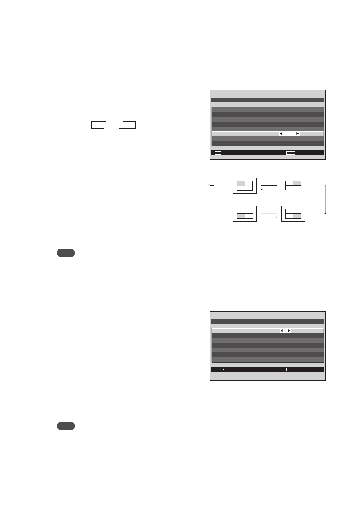
169
Integrator Mode
7 Setting the ABL LINK
This option synchronizes the screen brightness on the multiple displays that form a Video Wall.
Apply the AUTO ID function the select a screen divider option (other than OFF).
~ Place the cursor on ‘ABL LINK’ then press the [2/3]
buttons to change the settings.
Each time a [2/3] button is pressed, the setting changes
as shown below.
[Setting the ABL LINK]
ON ........... Brightness of each screen on the video wall is
the same (available for 4-panel and 9-panel
video walls only).
OFF ......... Brightness of the screens depends on the
setting of each display.
[Connecting four displays]
When this option is ‘ON’, connect the four displays
according to the POSITION sequence numbers in the
figure on the right with the combination cable (Mini-DIN,
6 pin). If the screen division or POSITION has changed,
the ABL link automatically turns off.
Note
Connect in the same way for a 9-panel video wall.
7 Setting the REPEAT TIMER
REPEAT TIMER duplicates the timed activities twice.
Apply the ‘AUTO ID’ function then select a screen divider option (other than OFF).
! Set the cursor on ‘REPEAT TIMER’ then press the [SET]
button.
@ Use the 5/∞/2/3 buttons to change settings.
[Setting the REPEAT TIMER]
DIVIDER ......... Setting the 1, 4, and 9 screen displays
SOURCE ........ Setting the input displayed
WORK TIME .. It can be set in 1 minute units up to 4
hours and 15 minutes
When the REPEAT TIMER has run twice, it alternately
switches between REPEAT TIMER1 and REPEAT
TIMER2. A video wall, only the panel in position ID1
controls all the settings.
Note
REPEAT TIMER goes in to effect when the OSD display disappears.
The ‘VIDEO WALL’ settings are common for all inputs.
Screen ~
3 ON
OFF 2
3
2
V I D E O WA L L
N O R M A L
O F F
O F F
:
:
:
O F F
:
SET EXITMENU
D I V I DE R
T Y P E
AU T O I D
P . O N DE L AY
A B L L I N K
R E P E A T T I M E R
R E T U R N
P O S I T I ON
Display 1
Display 2
Display 3
Display 4
No.1
No.2
No.3No.4
No.1
No.2
No.3No.4
No.1
No.2
No.3No.4
No.1
No.2
No.3No.4
COMBINATION
IN
COMBINATION
OUT
COMBINATION
OUT
COMBINATION
IN
COMBINATION
IN
COMBINATION
OUT
COMBINATION
OUT
COMBINATION
IN
Screen !
0 0 H 0 1 M
I NP UT 1
4
0 0 H 0 1 M
I NP UT 2
4
1
2
:
:
:
:
:
:
SET
SET
EXIT
MENU
D I V I DE R
WORK T I M E
R E P E A T T I M E R
S OURC E
D I V I DE R
WORK T I M E
S OURC E
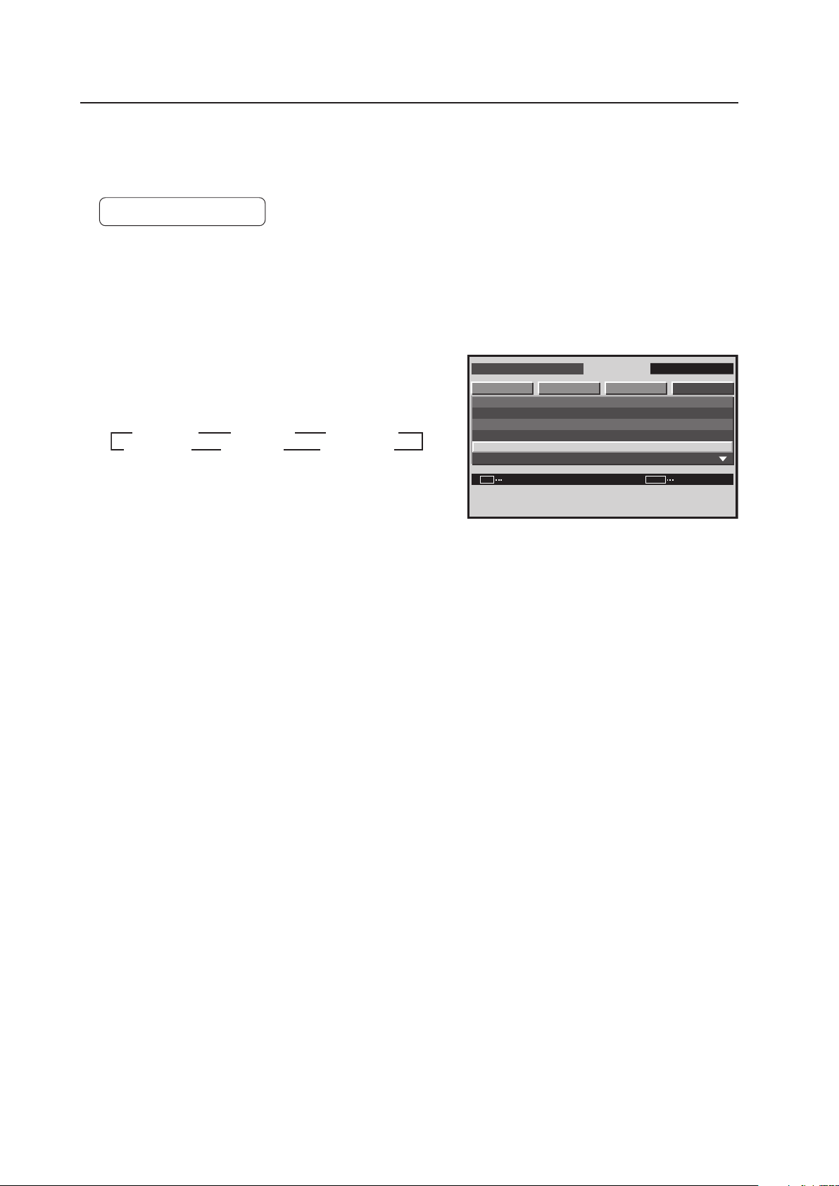
170
Integrator Mode
12) BAUD RATE Setting
It is possible to switch the RS-232C transmission speed (baud rate) when controlling or adjusting the display using a
PC. The baud rate can be set to 1200 bps, 2400 bps, 4800 bps, 9600 bps, 19200 bps, or 38400 bps.
Factory setting: 9600 bps
1 Enter the integrator mode.
(Refer to section 5.4.1, “About the Integrator Mode” (pg. 154).)
2 Select ‘OPTION’.
3 Place the cursor on ‘BAUD RATE’ then press the [SET]
button to change the setting.
Each time the [SET] button is pressed, the setting changes
as shown below.
The ‘BAUD RATE’ setting is common for all inputs.
Set the baud rate of the display so that it matches the baud rate of the PC.
Also, if the RS-232C cable must extend over a long distance, lower the baud rate.
I N T E G R ATO R I N P U T 1
CHANGE
S C R E E N S E T U P OP T I O NPICTURE
SET
EXIT
MENU
P R OG R A M T I M E R
S C R E E N M A S K
S I D E M A S K
V I D E O WA L L
BAU D R A T E
I D N O . SE T
:
:
:
G R E E N
0 1 H
3 8 4 0 0 B P S
Screen 3
3
4800BPS
9600BPS
3
19200BPS
3
38400BPS
2
1200BPS
2400BPS
2
2

171
Integrator Mode
13) Assigning an ID
This option assigns the ID necessary to adjust only the designated display in a video wall or to make an adjustment
using an RS-232C command. For details see “5.5 RS-232C Adjustment” (pg. 193).
Factory setting: ALL
1 Enter the integrator mode.
(Refer to section 5.4.1, “About the Integrator Mode” (pg. 154).)
2 Select ‘OPTION’.
3 Place the cursor on ‘ID NO. SET’ then press the [SET]
button.
4 Press the [2/3] buttons to change the settings.
Each time a [2/3] button is pressed, the setting changes
as shown below.
ALL ............... ID number cannot be set so the panel can
be operated from all remote controls.
01H to FFH ... The ID number is set to the designated
number. Display ID numbers may match the ID number that is displayed when the remote control’s
ID NO. SET button is pressed. The remote control’s ID NO. SET CLEAR button is operational.
Press the [SET] button to return to screen 3.
The ‘ID NO. SET’ settings are common for all inputs.
7 The Remote Control ID
When several Plasma Displays are installed at a single location, it is possible to operate only specified Plasma
Displays with the remote control. Set the following options:
1 Register panel ID numbers through the integrator menu.
2 Separately register the remote control for use with panel ID numbers.
Note
This function does not assign an ID number to the remote control; it assigns two kinds of panel IDs (Plasma Display
use and remote control use) to control each unit by combining these two IDs.
I N T E G R ATO R I N P U T 1
ENTER
S C R E E N S E T U P OP T I O NPI C T U R E
SET
EXIT
MENU
P R OG R A M T I M E R
S C R E E N M A S K
S I D E M A S K
V I D E O WA L L
BAU D R A T E
I D N O . SE T
:
:
:
G R E E N
0 1 H
1 2 0 0 B P S
Screen 3
I D N O. S E T
:
SET
SET EXIT
MENU
0 1 H
Screen 4
3 ALL 2 3 01H to FFH 2
Assigning ID to
the displays
To operate
only PDP 01
To operate
only PDP 02
Remote Control
ID: 01
Remote Control
ID: 02
Remote Control
ID: 02
Remote Control
ID: 02
Remote Control
ID: 02
Remote Control
ID: 01
Remote Control
ID: 01
Remote Control
ID: 01
PDP ID: 01 PDP ID: 02 PDP ID: 03 PDP ID: 04
ID matches only this PDP
ID matches only this PDP
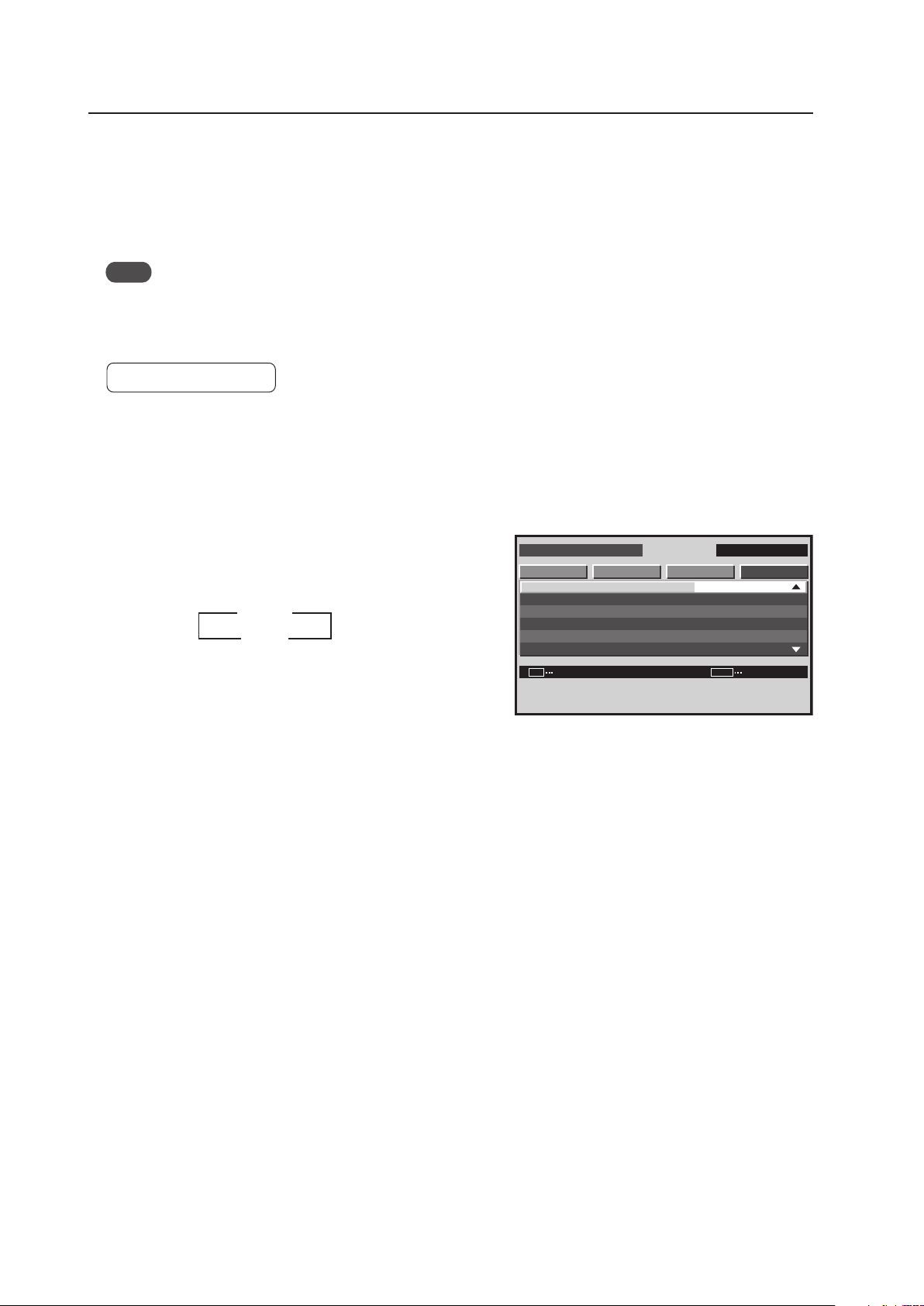
172
Integrator Mode
14) Cooling Fan Control Setting
A cooling fan is located on the rear surface of the display.
This function switches the method for controlling this fan.
For automatic control according to an internal temperature sensor, Set to ‘AUTO’.
For maximum rpm (AUTO CONTROL: OFF): Set to ‘MAX’.
Note
The ‘MAX’ setting is effective for special installations.
However, since the fan rotation noise increases, the effect on the surrounding area should be taken into consideration.
For details, refer to section 3, “Installation Site Requirements” (pg. 16).
Factory setting: AUTO
1 Enter the integrator mode.
(Refer to section 5.4.1, “About the Integrator Mode” (pg. 154).)
2 Select ‘OPTION’.
3 Place the cursor on ‘FAN CONTROL’ then press the [SET]
button to change the setting.
Each time the [SET] button is pressed, the setting changes
as shown below.
The ‘FAN CONTROL’ setting is common for all inputs.
Screen 3
I N T E G R ATO R I N P U T 1
CHANGE
S C R E E N S E T U P OP T I O N
F A N C O N T R O L
O S D
F RO N T I N D I C AT O R
C O L O R MOD E
P R O U S E
F R C
PICTURE
:
:
:
:
SET
EXIT
MENU
A U T O
N O R M A L
O N
O N
3
AUTO
MAX 2
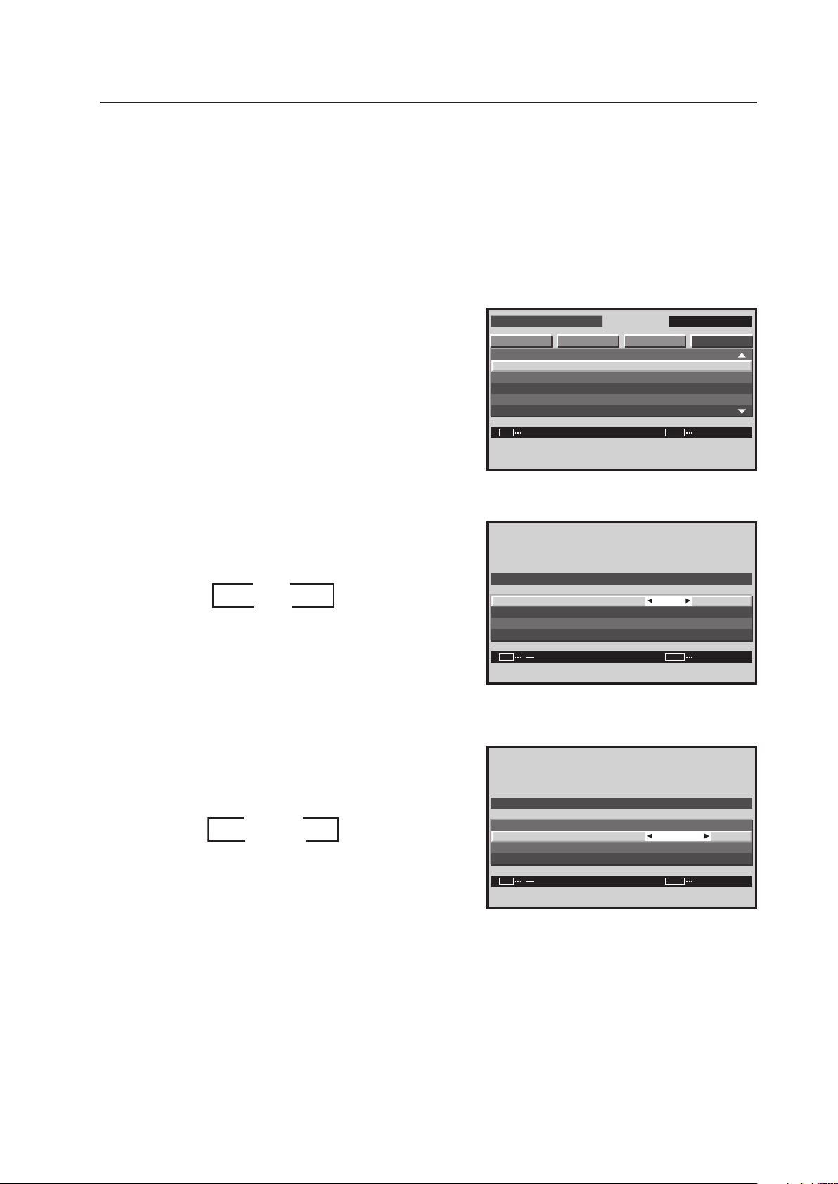
173
Integrator Mode
15) OSD Display Setting
This option allows the On-Screen-Display (OSD) menu to appear or to be hidden. OSD menu display features and
location are adjustable.
1 Enter the integrator mode.
(Refer to section 5.4.1, “About the Integrator Mode” (pg. 154).)
2 Select ‘OPTION’.
3 Place the cursor on ‘OSD’ then press the [SET] button.
7 Setting the Screen display
4 Place the cursor on ‘DISPLAY’ then use the [2/3] buttons
to change the settings.
Each time a [2/3] button is pressed, the setting changes
as shown below.
ON ....... Pressing the MENU button displays the menu.
OFF ..... Even if the MENU button is pressed, the menu
is not displayed.
7 Setting the Screen size
5 Place the cursor on ‘SIZE’ then use the [2/3] buttons to
change the settings.
Each time a [2/3] button is pressed, the setting changes
as shown below.
LARGE ..... The display is doubled horizontally and
vertically.
SMALL ..... The display appears in original size.
D I S PL AY
O S D
S I Z E
A N G L E
R E T U R N
:
:
:
SET EXITMENU
L A R G E
H
O N
Screen 4
Screen 3
I N T E G R ATO R I N P U T 1
ENTER
S C R E E N S E T U P OP T I O N
F A N C O N T R O L
O S D
F RO N T I N D I C AT O R
C O L O R MOD E
P RO US E
F R C
PICTURE
:
:
:
:
SET
EXIT
MENU
A U T O
N O R M A L
O N
O N
3
3
ON
OFF 2
2
3
3
LARGE
SMALL
2
2
Screen 5
D I S PL AY
O S D
S I Z E
A N G L E
R E T U R N
:
:
:
SET EXITMENU
L A R G E
H
O N
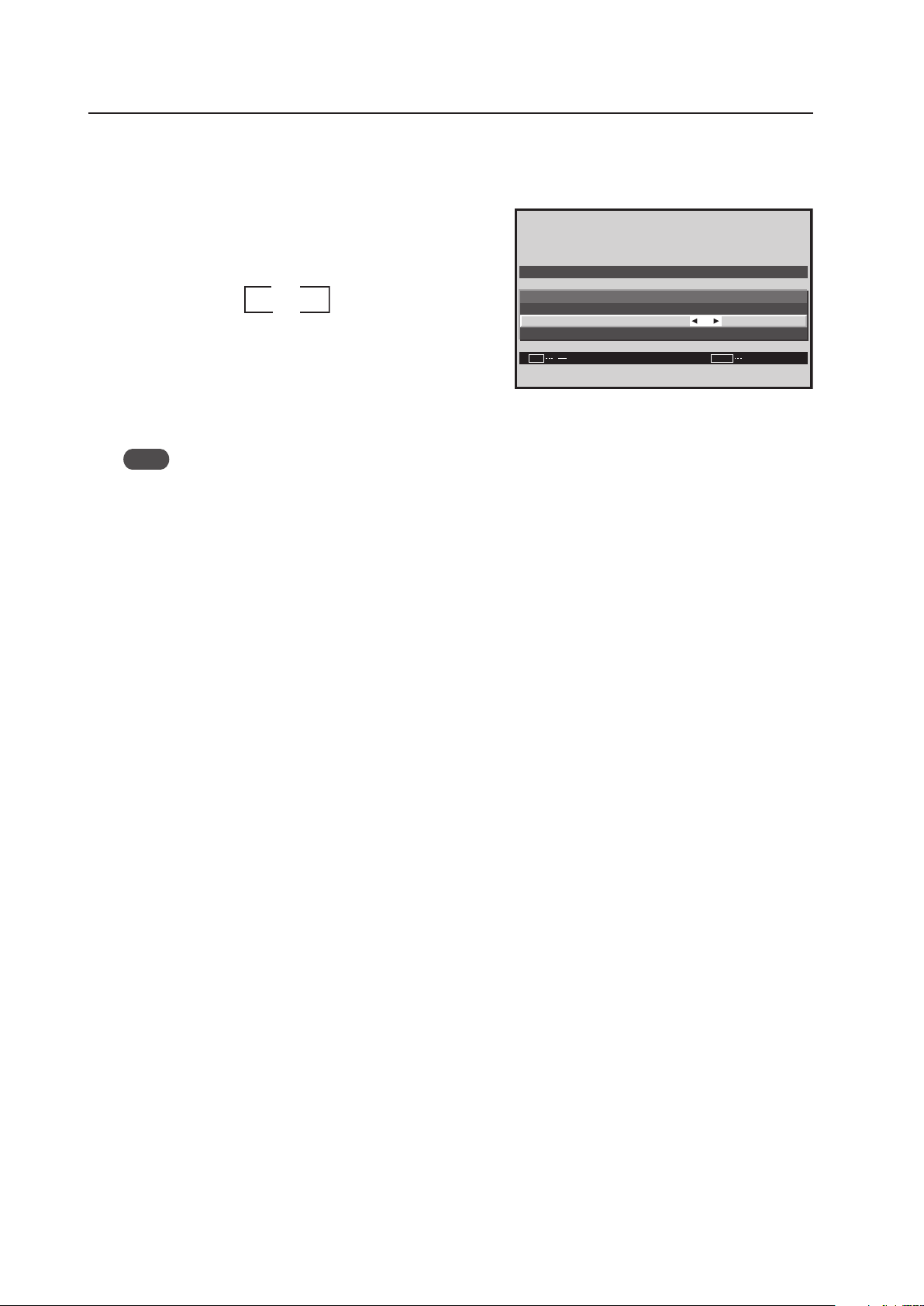
174
Integrator Mode
7 Setting the display mode
If the display is installed vertically, set the display mode to ‘V’.
6 Place the cursor on ‘ANGLE’ then use the [2/3] buttons
to change the settings.
Each time a [2/3] button is pressed, the setting changes
as shown below.
H ...... The menu is displayed horizontally.
V ....... Because it is positioned vertically, the menu is
displayed rotated 90°. The menu language is
English.
Note
To return it to a vertical display, from the menu mode, select ‘OPTION‘ = ‘OSD ANGLE’ = ‘H’-.
Screen 6
D I S PL AY
O S D
S I Z E
A N G L E
R E T U R N
:
:
:
SET
EXIT
MENU
L A R G E
H
O N
3
3
H
V 2
2
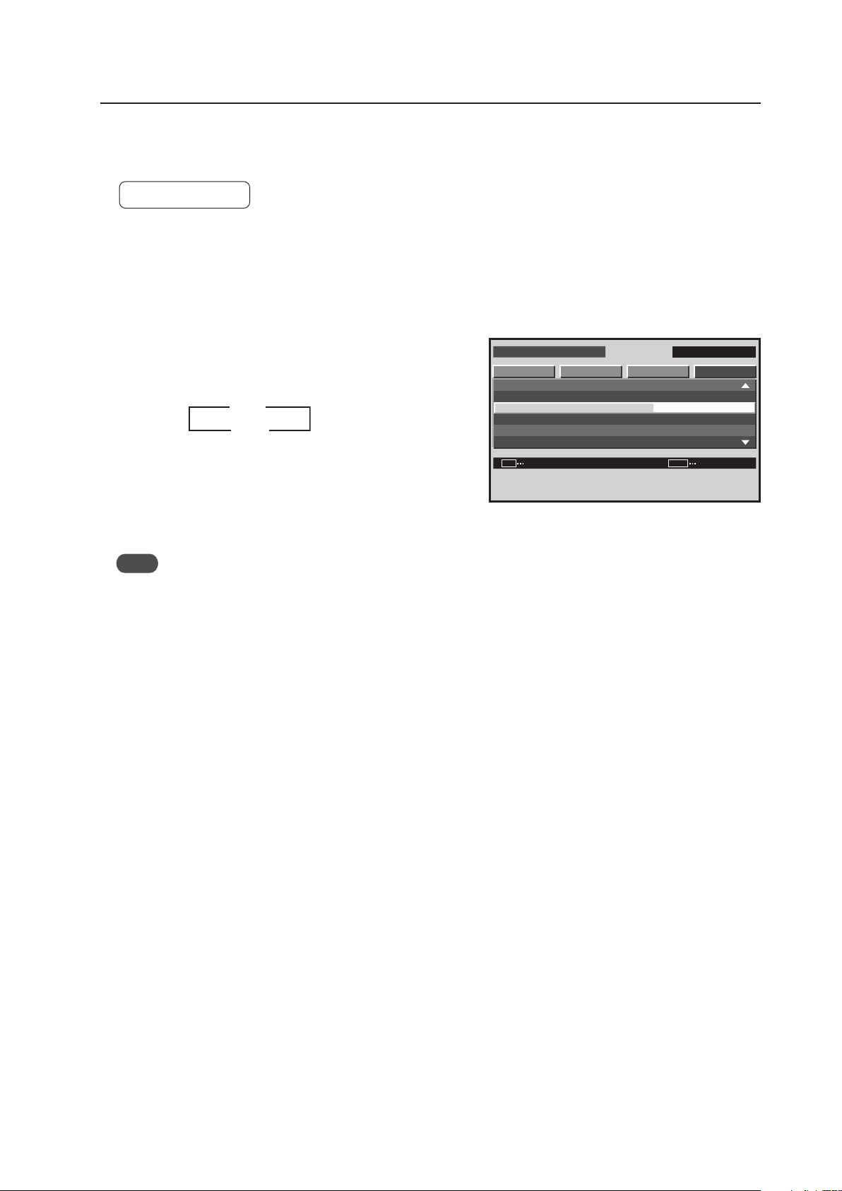
175
Integrator Mode
16) FRONT INDICATOR Setting
This function controls the flashing of the indicator on the front of the display.
Factory setting: ON
1 Enter the integrator mode.
(Refer to section 5.4.1, “About the Integrator Mode” (pg. 154).)
2 Select ‘OPTION’.
3 Place the cursor on ‘FRONT INDICATOR’ then press the
[SET] button to change the setting.
Each time the [SET] button is pressed, the setting changes
as shown below.
ON: Normal LED function
OFF: Lights red during standby
The ‘FRONT INDICATOR’ setting is common for all inputs.
Note
Regardless of the ON/OFF setting, during POWER MANAGEMENT operation and shutdown, the green indicator
flashes.
Screen 3
I N T E G R ATO R I N P U T 1
CHANGE
S C R E E N S E T U P OP T I O N
F A N C O N T R O L
O S D
F RO N T I N D I C AT O R
C O L O R MOD E
P RO US E
F R C
PICTURE
:
:
:
:
SET
EXIT
MENU
A U T O
N O R M A L
O N
O N
3
ON
OFF 2
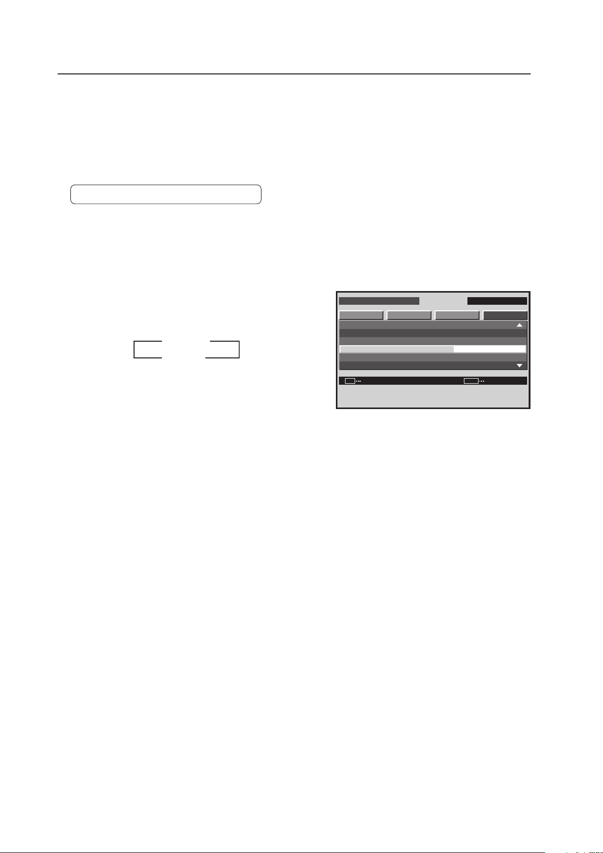
176
Integrator Mode
17) COLOR MODE Setting
In addition to the normal operation mode (NORMAL), this display has a (STUDIO) mode for use in a TV studio. The
adjustment values for ‘PICTURE’ and ‘SCREEN’ can be set independently.
(Refer to section 5.4.4, “PICTURE, White Balance and SCREEN position Adjustment Values Memory Area Tables”
(pg. 188).)
Change the settings to meet the desired usage.
Factory setting: COLOR MODE: NORMAL
1 Enter the integrator mode.
(Refer to section 5.4.1, “About the Integrator Mode” (pg. 154).)
2 Select ‘OPTION’.
3 Place the cursor on ‘COLOR MODE’ then press the [SET]
button to change the setting.
Each time the [SET] button is pressed, the setting changes
as shown below.
When the ‘COLOR MODE’ setting is changed, all input
functions as well as the ‘PICTURE’ and ‘SCREEN’
adjustment values for the input signal are changed.
The ‘COLOR MODE’ setting is common for all inputs.
I N T E G R ATO R I N P U T 1
CHANGE
S C R E E N S E T U P OP T I O N
F A N C O N T R O L
O S D
F RO N T I N D I C AT O R
C O L O R MOD E
P RO US E
F R C
PICTURE
:
:
:
:
SET
EXIT
MENU
A U T O
N O R M A L
O N
O N
Screen 3
STUDIO
NORMAL
2
3
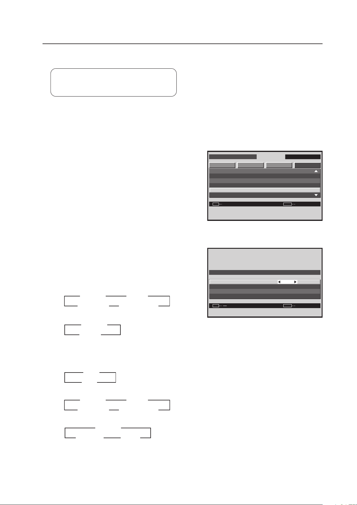
177
Integrator Mode
18) PRO USE Setting
Factory setting: UNDERSCAN ............ OFF
IMAGE PROCESS ..... NORMAL
SIGNAL TYPE ............ MOTION
1 Enter the integrator mode.
(Refer to section 5.4.1, “About the Integrator Mode” (pg. 154).)
2 Select ‘OPTION’.
3 Place the cursor on ‘PRO USE’ then press the [SET]
button.
4 Place the cursor on the desired item then use the [2/3]
buttons to change the setting.
Each time a [2/3] button is pressed, the setting changes
as shown below.
For PC signal input
• IMAGE PROCESS
• SIGNAL TYPE
For video signal input (Applicable only when a PDA-5003
or PDA-5004 is installed.)
• UNDERSCAN
• IMAGE PROCESS
• SIGNAL TYPE
I N T E G R ATO R I N P U T 1
ENTER
S C R E E N S E T U P OP T I O N
F A N C O N T R O L
O S D
F RO N T I N D I C AT O R
C O L O R MOD E
P RO US E
F R C
PICTURE
:
:
:
:
SET EXITMENU
A U T O
N O R M A L
O N
O N
Screen 3
O F F
N O R M A L
S T I L L
U N D E R S C A N
I M AG E P R O C E S S
S I G N AL T Y P E
R E T U R N
:
:
:
SET
EXIT
MENU
P R O U S E
Screen 4
3
3
ON
OFF
2
2
MOTION
STILL
3
2
2
NON STD
3
2 3
NORMAL PURE
3
2
MONO TONE
2
22
HIGH CNT
2
3 3
NORMAL PURE
3
2
MONO TONE
2
22
HIGH CNT
2
3 3
3
3 STILL
MOTION
2
2

178
Integrator Mode
UNDERSCAN
This function causes the outer edge of the display to appear, beyond the normal effective data area for a video signal.
[Method of Use]
After setting the UNDERSCAN setting to ON and leaving the MENU mode, select ‘UNDERSCAN’ with the remote
control’s SCREEN SIZE button.
Note
Due to signal path loss or internal-circuit loss, the position may shift a little. However, since the display position
cannot be adjusted using SIZE adjustment, adjust the display position at the source.
IMAGE PROCESS
Match the image to a specified display use.
NORMAL .......... Performs a normal display
PURE ................ Displays the input image as faithfully as possible
MONO TONE ... Cuts the color components of the image signal to display only the brightness signal
HIGH CNT ......... Strengthens the contrast above the NORMAL level to raise the color temperature to approximately
+2000 K
Note
Even when set to ‘MONO TONE’, color appears according to the adjustment of the white balance. To correct this,
readjust the white balance.
SIGNAL TYPE
When performing YC separation (CVBS signal only) or IP conversion processing (interlace signal only), it is possible
to set the image quality for a still image.
Normally, MOTION is set.
When performing YC separation or IP conversion processing, STILL locks the still image without showing motion.
On a still image screen that may screen to have motion (blades of grass or forest), set to STILL.
Screen rolling may occur occasionally depending on the degree of degradation of the input signal. If this happens,
Set to NON STD to solve this issue.
Notes
• When STILL is set for a moving image, the picture quality may deteriorate.
• 3D Y/C processing is not performed in the NON STD mode. When this mode is set for a standard signal color,
noise slightly may increase. Switching CTI to OFF can alleviate color noise depending on the screen pattern (refer
to section 5.3.7, “5) CTI Setting” (pg. 135)).
• The NON STD mode is effective for NTSC CVBS (composite video signal).
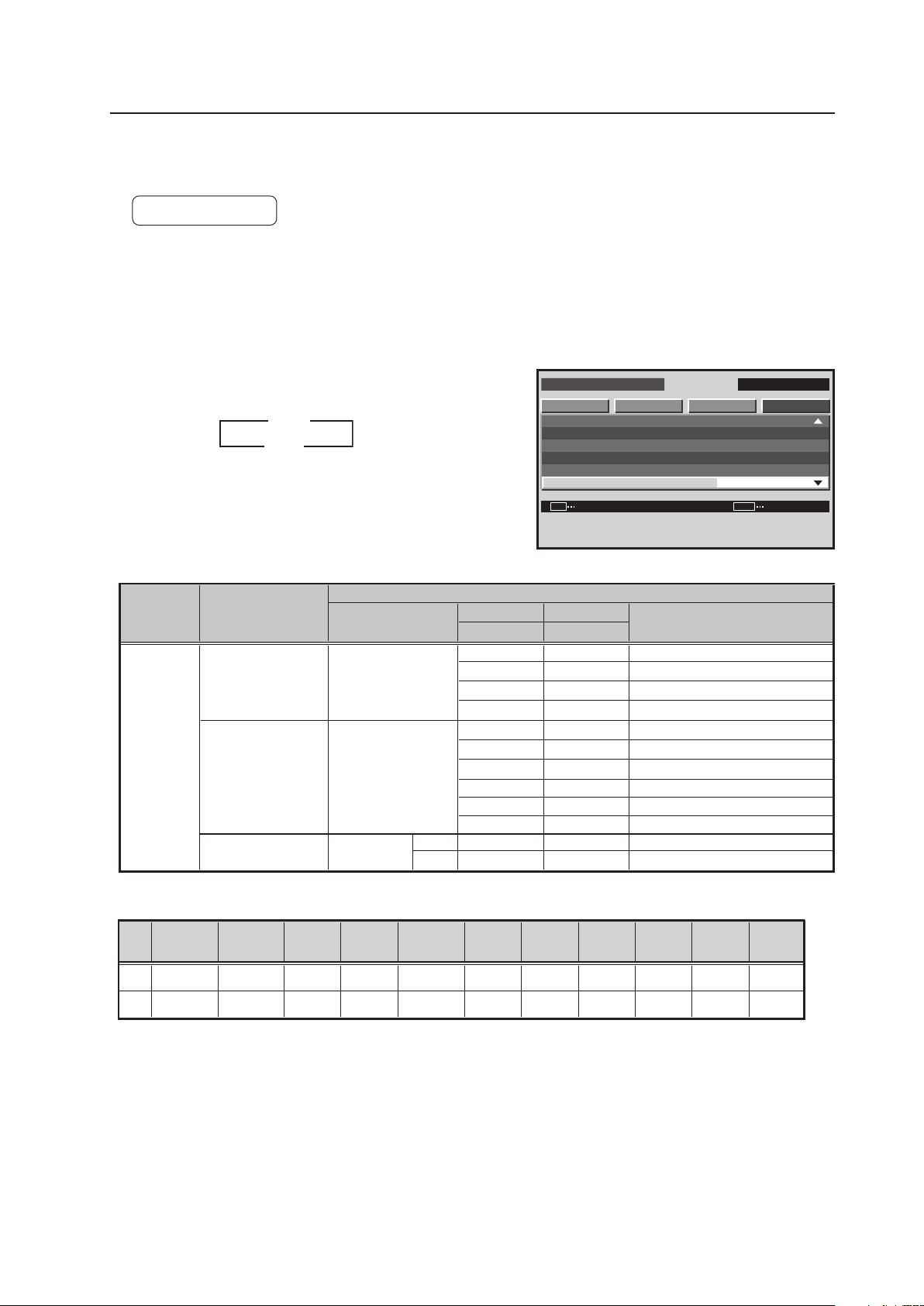
179
Integrator Mode
I N T E G R ATO R I N P U T 1
CHANGE
S C R E E N S E T U P OP T I O N
F A N C O N T R O L
O S D
F RO N T I N D I C AT O R
C O L O R MOD E
P RO US E
F R C
PICTURE
:
:
:
:
SET EXITMENU
A U T O
N O R M A L
O N
O N
3
ON
OFF
2
Retake at a TV studio
(PAL camera)
49.67
Retake at a TV studio
(NTSC camera)
FILM re-shoot for a movie
(48 Hz camera)
59.94
60.00
60.00
49.54
50.08
49.861
59.87
60.02
60.00
48.003
48.014
*1, 2: The recommended signal formats are shown below.
Dot Clock
H-Period
H-Sync
H-BP
V-Period
H-sync
polarity
OFF
*1 52MHz
1344dot
nega
nega
806line
802line
V-Sync
4line
4line
V-BP
31line
29line
V-Disp
768line
768line
134dot
118dot
*2 65MHz
1688dot
163dot
242dot
H-Disp
1024dot
1280dot
V-sync
polarity
nega
nega
FRC
MODE
Use
PC
Horizontal frequency
Fh (kHz)
Vertical frequency
Fv (Hz)
Remarks
PC
50Hz
PC
60Hz
PC
48Hz
*1
*2
640 x 480
24.69
640 x 480
848 x 480
1024 x 768
48.36
848 x 480
24.62
40.365
39.988
31.47
31.02
1024 x 768
1280 x 768
47.78
1280 x 1024
63.98
1400 x 1050
65.32
38.69
38.51
1024 x 768
1280 x 768
1280 x 768
Input correspondence signals
19) FRC Setting
This option allows switching of the frame rate conversion.
Factory setting: ON
1 Enter the integrator mode.
(Refer to section 5.4.1, “About the Integrator Mode” (pg. 154).)
2 Select ‘OPTION’.
3 Place the cursor on ‘FRC’ then press the [SET] button.
Each time the [SET] button is pressed, the setting changes
as shown below.
ON ........... Changes the frame rate.
OFF ......... Does not change the frame rate.
The ‘FRC’ setting is common for all inputs.
Screen 3
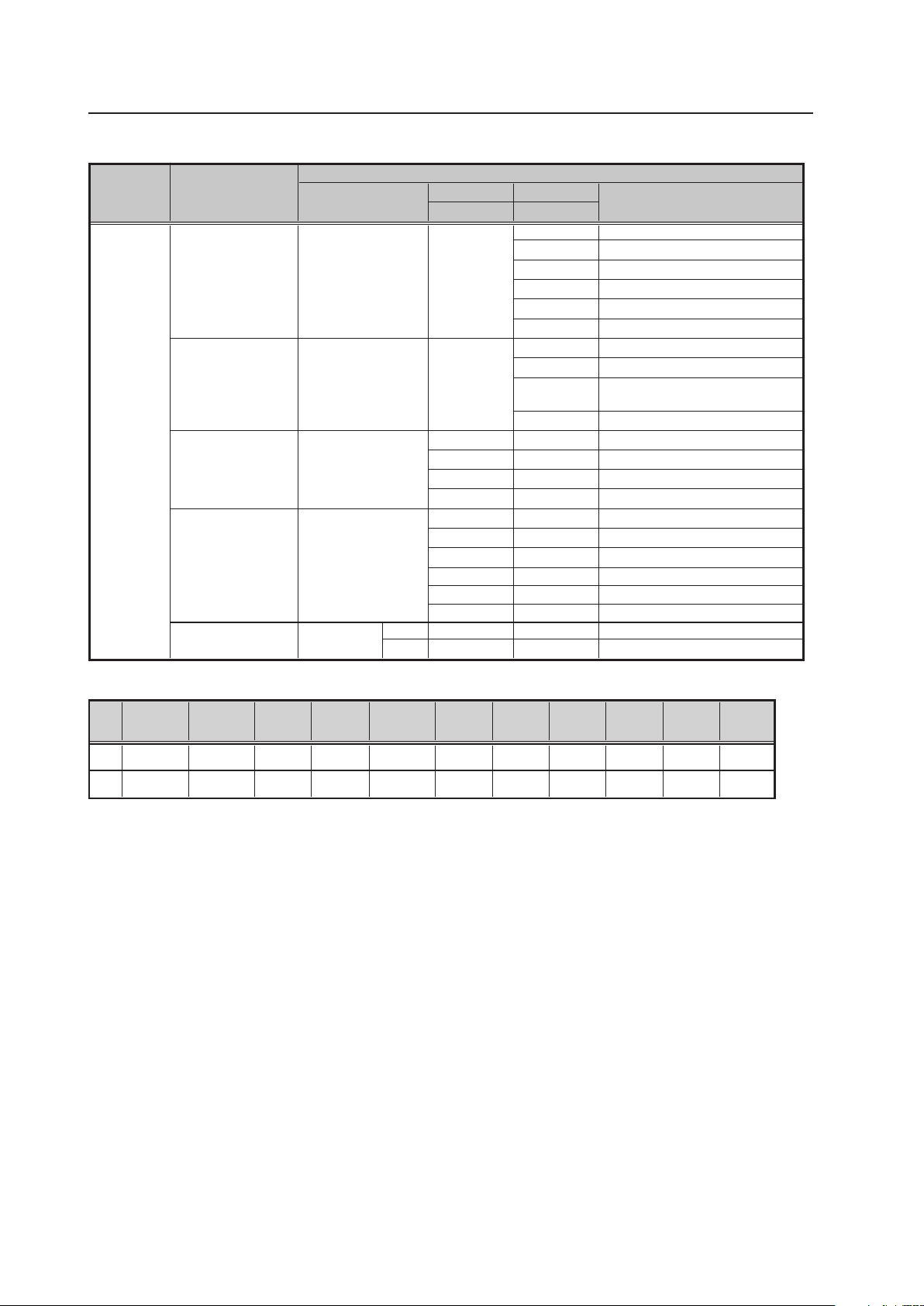
180
Integrator Mode
*1, 2: The recommended signal formats are shown below.
★ Applicable only when a PDA-5003 or PDA-5004 is installed.
Dot Clock
H-Period
H-Sync
H-BP
V-Period
H-sync
polarity
*1 52MHz
1344dot
nega
nega
806line
802line
V-Sync
4line
4line
V-BP
31line
29line
V-Disp
768line
768line
134dot
118dot
*2 65MHz
1688dot
163dot
242dot
H-Disp
1024dot
1280dot
V-sync
polarity
nega
nega
Retake at a TV studio
(PAL camera)
50
Retake at a TV studio
(PAL camera)
49.67
Retake at a TV studio
(NTSC camera)
60
Retake at a TV studio
(NTSC camera)
FILM re-shoot for a movie
(48 Hz camera)
59.94
60.00
60.00
49.54
50.08
49.861
59.87
60.02
60.00
48.003
48.014
OFF
FRC
MODE
Use
VIDEO/PC
Horizontal frequency
Fh (kHz)
Vertical frequency
Fv (Hz)
Remarks
VIDEO
50Hz
PC
50Hz
VIDEO
60Hz
PC
60Hz
PC
48Hz
*1
*2
625i (576i)/SDTV
15.63
1125i (1080i)/HDTV
28.13
750p (720p)/HDTV
37.5
1125p (1080p)/HDTV
56.25
1125i (1080i)/HDTV
1125i (1035i)/HDTV
33.75
1250p/HDTV
62.5
1125p (1080p)/HDTV
67.5
640 x 480
24.69
640 x 480
848 x 480
1024 x 768
48.36
848 x 480
24.62
40.365
39.988
31.47
31.02
1024 x 768
1280 x 768
47.78
1280 x 1024
63.98
1400 x 1050
65.32
38.69
38.51
1024 x 768
1280 x 768
1280 x 768
525i (480i)/SDTV
15.75
525p (480p)/SDTV
31.5
625p (576p)/SDTV
31.25
Input correspondence signals
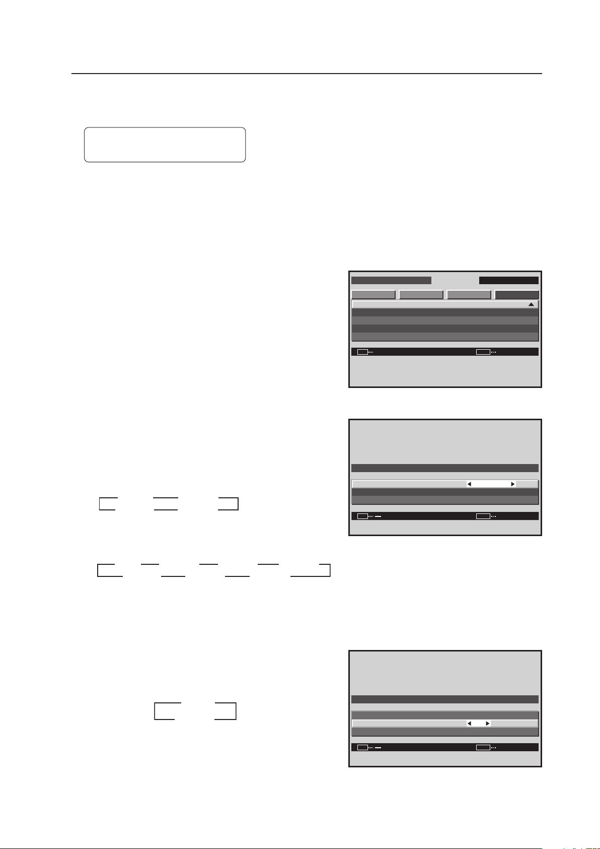
181
Integrator Mode
20) POWER ON MODE Setting
This function sets the input at the time the power is switched on.
Factory setting: INPUT.......... LAST
VOLUME ..... LAST
1 Enter the integrator mode.
(Refer to section 5.4.1, “About the Integrator Mode” (pg. 154).)
2 Select ‘OPTION’.
3 Place the cursor on ‘PWR. ON MODE’ then press the
[SET] button.
4 Place the cursor on ‘INPUT’ then use the [2/3] buttons
to change the settings.
Each time a [2/3] button is pressed, the setting changes
as shown below.
For PC signal input
For video signal input (Applicable only when a PDA-5003/
PDA-5004 is installed.)
Select ‘MULTI’ then press the [SET] button to change to
two-screen input.
5 Place the cursor on ‘VOLUME’ then use the [2/3] buttons
to change the settings.
Each time a [2/3] button is pressed, the setting changes
as shown below.
Screen 3
I N T E G R ATO R I N P U T 1
ENTER
S C R E E N S E T U P OP T I O N
P W R . O N MO D E
S E A M L E S S S W
M I R R O R MO D E
M U L T I S C R EE N S E T
F U N C T I O N RE S E T
PICTURE
:
SET
EXIT
MENU
O F F
INPUT2
INPUT1
LAST
3 3
INPUT3
INPUT4
INPUT5
3
MULTI
3
222
3 3 3
2222
Screen 4
0
I N P U T I N P U T 1
VO L U M E
RE T U R N
:
:
:
SET EXITMENU
P W R . O N MO D E
Screen 5
INPUT1
LAST
3
3
MULTI
22
3 3
22
INPUT2
0
I N P U T
I N P U T 1
VO L U M E
RE T U R N
:
:
:
SET
EXIT
MENU
P W R . O N MO D E
3
3
0 to 42
LAST
2
2
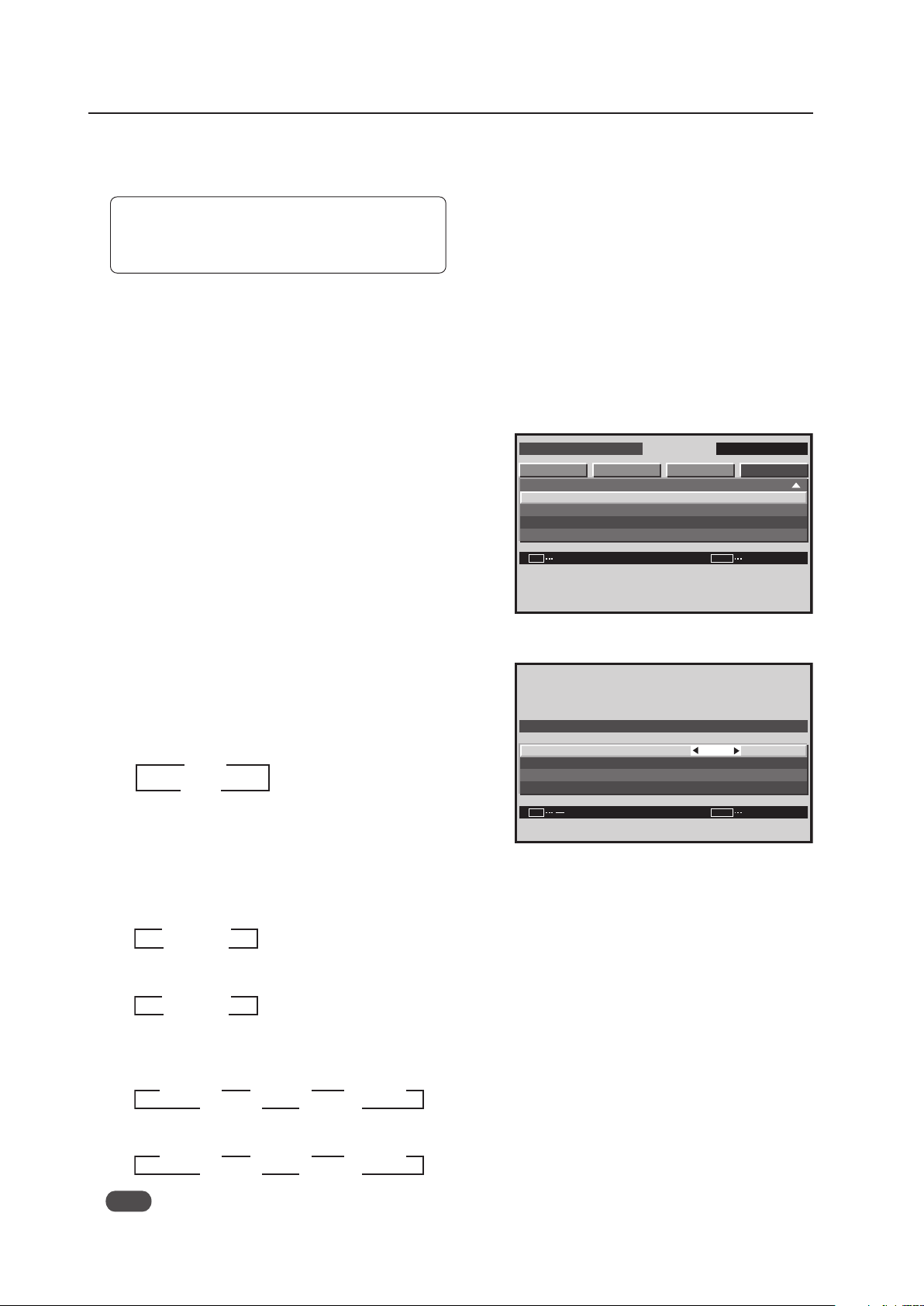
182
Integrator Mode
21) SEAMLESS SW Setting
This setting switches between inputs at a speed of approximately 0.4 seconds.
Factory setting: SEAMLESS .................. OFF
SELECT1 ...................... INPUT1
SELECT2 ...................... INPUT2
1 Enter the integrator mode.
(Refer to section 5.4.1, “About the Integrator Mode” (pg. 154).)
2 Select ‘OPTION’.
3 Place the cursor on ‘SEAMLESS SW’ then press the [SET]
button.
4 Place the cursor on an item then use the [2/3] buttons
to change the settings.
Each time a [2/3] buttons are pressed, the setting
changes as shown below.
• SEAMLESS SW
ON........... The inputs set by ‘SELECT1’ and by ‘SELECT2’
are switched rapidly by the SWAP button
OFF ......... High speed switching does not occur
For PC signal input
• SELECT1
• SELECT2
For video signal input (Applicable only when a PDA-5003/PDA-5004 is installed.)
• SELECT1
• SELECT2
Note
During two-screen display and video wall, high speed switching is unavailable.
Screen 3
Screen 4
I N T E G R ATO R I N P U T 1
ENTER
S C R E E N S E T U P OP T I O N
P W R . O N MO D E
S E A M L E S S S W
M I R R O R MO D E
M U L T I S C R EE N S E T
F U N C T I O N RE S E T
PICTURE
:
SET
EXIT
MENU
X
O F F
I N P U T 1
I N P U T 2
S E L E C T 1
S E L E C T 2
RE T U R N
:
:
:
SET
EXIT
MENU
S E A M L E S S S W
S E A M L E S S SW
3
3
ON
OFF
2
2
INPUT2
INPUT1
3
INPUT3
INPUT4
INPUT5
3
3
22
222
3 3
INPUT2
INPUT1
3
INPUT3
INPUT4
INPUT5
3
3
22
222
3 3
INPUT1
INPUT2
3
2
2
3
INPUT1
INPUT2
3
2
2
3
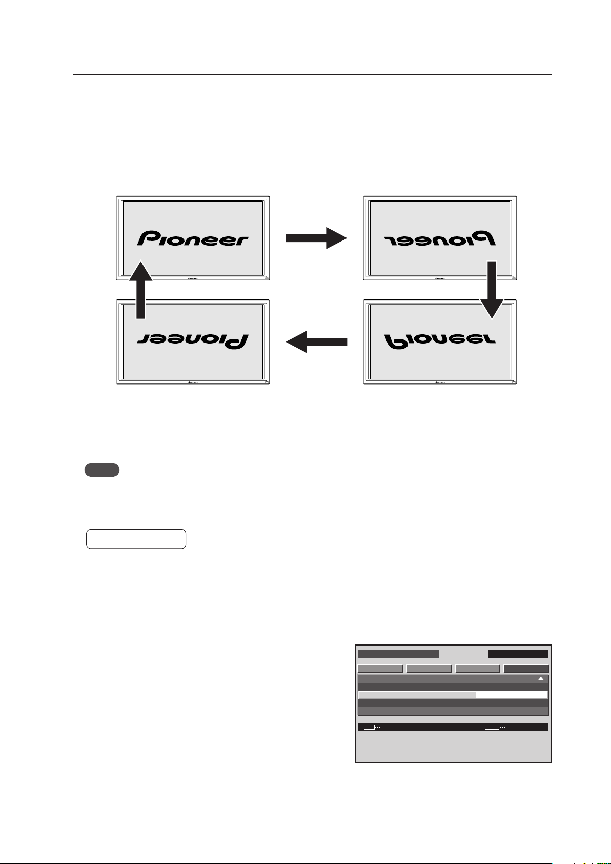
183
Integrator Mode
The ‘MIRROR MODE: XY’ setting is useful when the panel is hung upside down from the ceiling. With the display
suspended from the PDK-5012 mount, run the bundled cables up toward the ceiling.
Notes
• To reverse an up-down setting, set ‘MIRROR MODE’ to ‘XY’ or ‘Y’.
• When using the PDK-5012 ceiling mount, pay attention to the operating temperature conditions (Refer to section
4.8, “Ceiling Mount Unit: PDK-5012” (pg. 76)).
Factory setting: OFF
1 Enter the integrator mode.
(Refer to section 5.4.1, “About the Integrator Mode” (pg. 154).)
2 Select ‘OPTION’.
3 Place the cursor on ‘MIRROR MODE’ then press the [SET]
button to change the setting.
22) MIRROR MODE Setting
This function reverses the image displayed on the screen in various ways.
For normal reproduction: Set to ‘MIRROR MODE: OFF’
For left-right reversed reproduction: Set to ‘MIRROR MODE: X’
For up-down reversed reproduction: Set to ‘MIRROR MODE: Y’
For up-down, left-right reproduction: Set to ‘MIRROR MODE: XY’
Screen 3
Up-down reversal
Normal operating state
Left-right reversal
Up-down, left-right reversal
[MIRROR MODE: OFF]
[MIRROR MODE: XY]
[MIRROR MODE: X]
[MIRROR MODE: Y]
I N T E G R ATO R I N P U T 1
CHANGE
S C R E E N S E T U P OP T I O N
P W R . O N MO D E
S E A M L E S S S W
M I R R O R MO D E
M U L T I S C R EE N S E T
F U N C T I O N RE S E T
PICTURE
:
SET EXITMENU
X

184
Integrator Mode
4 Each time the [SET] button is pressed, the setting changes
as shown below (the OSD is also reversed).
The ‘MIRROR MODE’ setting is common for all inputs.
I N T E G R ATO R I N P U T 1
CHANGE
S C R E E N S E T U P OP T I O N
P W R . O N MO D E
S E A M L E S S S W
M I R R O R MO D E
M U L T I S C R EE N S E T
F U N C T I O N RE S E T
PICTURE
:
SET
EXIT
MENU
X
Screen 4
OFF
XY
X
Y
3
3
2 2
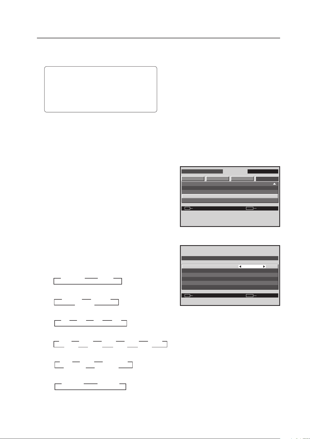
185
Integrator Mode
23) MULTISCREEN Setting
This function divides the screen into two areas when the remote control’s SPLIT button is pressed.
Factory setting: S BY S SIZE.................. NORMAL
S BY S LAYOUT ........... MODE1
PIP SIZE ....................... 2
TRANSLUCENT PIP ..... OFF
BANNER PIP ................ OFF
BANNER INPUT ........... INPUT1
1 Enter the integrator mode.
(Refer to section 5.4.1, “About the Integrator Mode” (pg. 154).)
2 Select ‘OPTION’.
3 Place the cursor on ‘MULTISCREEN SET’ then press the
[SET] button.
4 Place the cursor on an item then use the [2/3] buttons
to change the settings.
Each time a [2/3] button is pressed, the setting changes
as shown below.
• S BY S SIZE
• S BY S LAYOUT
• PIP SIZE
• TRANSLUCENT PIP
• BANNER PIP
• BANNER INPUT
Press the [SET] button to return to screen 2.
Screen 3
Screen 4
I N T E G R ATO R I N P U T 1
ENTER
S C R E E N S E T U P OP T I O N
P W R . O N MO D E
S E A M L E S S S W
M I R R O R MO D E
M U L T I S C R EE N S E T
F U N C T I O N RE S E T
PICTURE
:
SET
EXIT
MENU
X
MOD E 1
N O R M A L
8 0
4
SET
P I P S I Z E
S BY S L AYO U T
S BY S S I Z E
T R A N S L U C E N T P I P
BA N N E R P I P
BA N N E R I N P U T
:
:
:
:
:
:
SET EXITMENU
M U LT I S C R E E N S E T
I NP U T 1
O F F
%
NORMAL
FULL
3
33
3
MODE2
MODE1
3
MODE3
3
3
2
22
2
1
3
4
3
3
3
3
3 3 33
10%
OFF
3
3
20%
3
30%
3
40%
3
50%60%70%80%
3 3 3 3
33333
3333
TOP
OFF
3
3
MID HIGH
3
BOTTOM
3
MID LOW
3
3
333
3
INPUT1 INPUT2
3
33
3
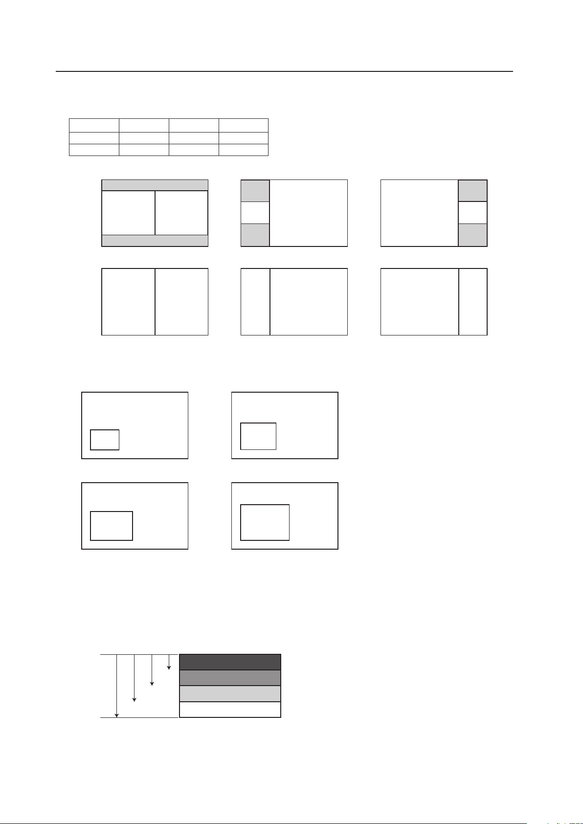
186
Integrator Mode
S BY S SIZE/S BY S LAYOUT
Select a SIDE BY SIDE mode display, six options.
MODE1 MODE2 MODE3
NORMAL SBYS1 SBYS2 SBYS3
FULL SBYS4 SBYS5 SBYS6
PIP SIZE
Select the size of the PICTURE IN PICTURE sub-screen.
TRANSLUCENT PIP
Select the degree of transparency for the PICTURE IN PICTURE sub-screen.
As the translucent percentage rises, the sub-screen becomes less visible, fades.
BANNER PIP
Select the PICTURE IN PICTURE sub-screen position from the locations shown below.
The Banner sub-screen option uses only the top 1/4 of a PC signal input. For example, to add a picture or text as a
banner from Microsoft PowerPoint, the image or text must be placed in the top 1/4 area of the slide(s).
It can be selected only with INPUT1 and INPUT2.
TOP
MID HIGH
MID LOW
BOTTOM
192
384576768
1024
A
B
A B
A
B
A
B
B
A
B
A
512 (512) 512 (512)
512 512 256 768 768 256
512
(384)
768
256
(192)
768 768
256
(192)
768
(768)
768
(768)
256
(256)
768
(576)
768
(576)
256
(192)
SIDE BY SIDE1
SIDE BY SIDE2 SIDE BY SIDE3
SIDE BY SIDE4
SIDE BY SIDE5 SIDE BY SIDE6
B
B
B
B
A
A
A
A
256
(256)
256
(192)
330
(330)
480
(480)
330
(248)
480
(360)
405
(405)
405
(304)
PIP1
PIP2
PIP3 PIP4

187
Integrator Mode
24) FUNCTIONAL LOCK
This is the FUNCTIONAL LOCK function that prevents operation from the main unit panel or the remote control in
order to prevent improper operation after installation (The RS-232C command is effective.)
While the FUNCTIONAL LOCK is set, if the remote control or main unit operating panel are operated, the following
are displayed in the center of the screen.
• ‘BUTTONS LOCK’
• ‘IR LOCK’
• ‘BUTTONS & IR LOCK’
• ‘MEMORY LOCK‘ *
* ‘MEMORY LOCK‘
The input functions, volume, and multi-screen display status when ‘MEMORY LOCK‘ is set are stored in memory,
and when the power is turned on, the display complies with this information.
When it is shipped from the factory, the LOCK is set to off, so the remote control and the main unit panel can be
operated.
Factory setting: LOCK off
The following are two setting methods.
1) Main unit operating panel (concealed)
Each time the [FUNCTIONAL LOCK (concealed)] button is pressed, the switching occurs in the following sequence.
To turn the LOCK off, press and hold the [FUNCTIONAL LOCK (concealed)] button for at least about 5 seconds.
2) RS-232C command
Refer to “5.5.5 List of RS-232C Commands (pg. 198)“.
3 3 IR LOCK 3 3BUTTONS & IR LOCK
BUTTONS LOCK MEMORY LOCK
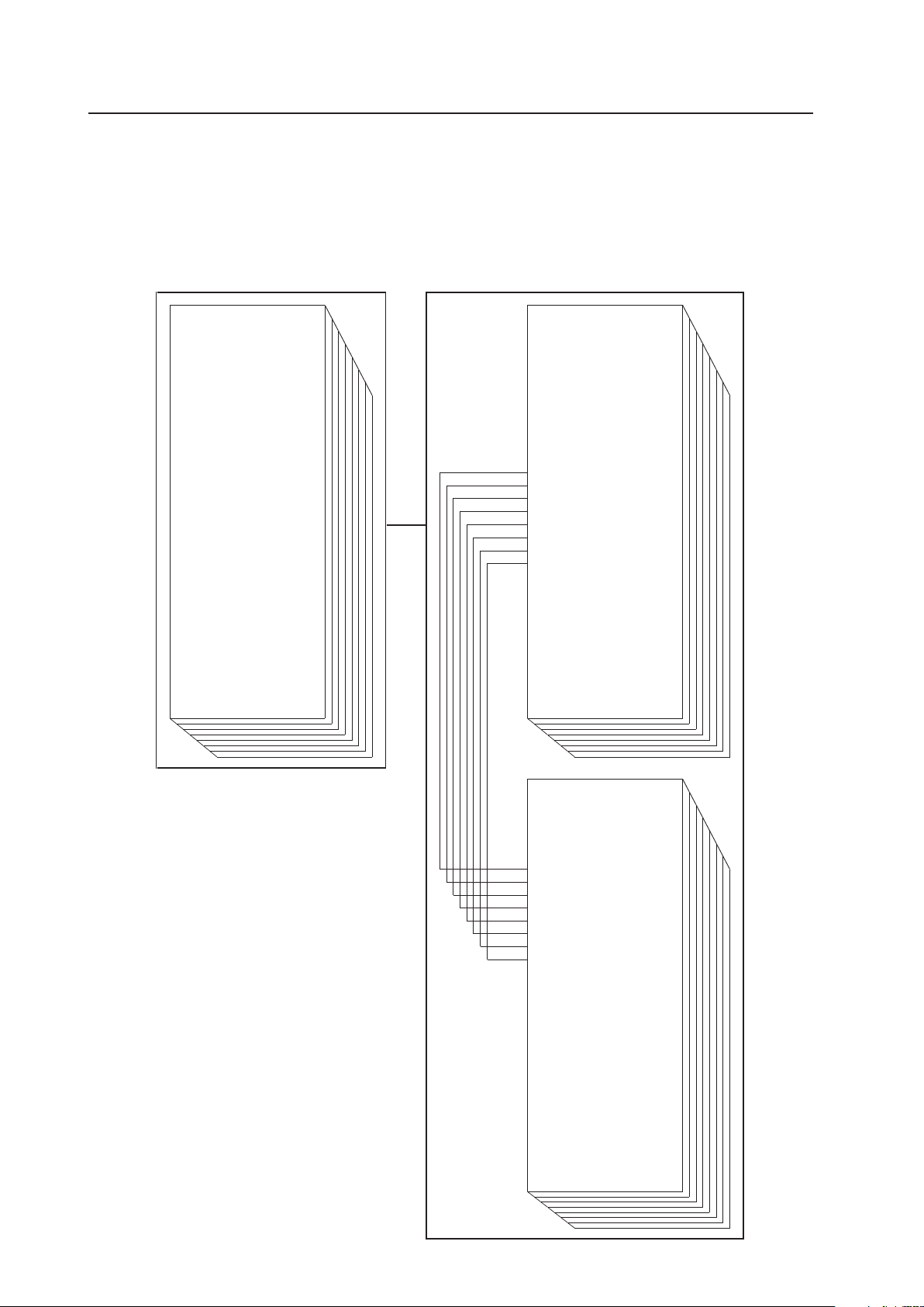
188
Integrator Mode
5.4.4 PICTURE, White Balance and SCREEN Position Adjustment Values Memory Area Tables
The memory areas for the PICTURE, White Balance and SCREEN adjustment values have the configuration shown
below. Adjustments in the menu mode share the same memory as the COLOR MODE NORMAL and STUDIO. The
adjustment values in the integrator mode are stored in memory that is separate from that for COLOR MODE NORMAL
and STUDIO.
7 INPUT1
¥CONTRAST
¥BRIGHTNESS
¥H. ENHANCE !
¥V. ENHANCE !
¥COLOR
★
¥TINT
★
¥SHARPNESS
★
¥H. POSITION
¥V. POSITION
¥CLOCK !
¥PHASE !
¥COLOR TEMP.
★
¥DNR
★
¥MPEG NR
★
¥CTI
★
¥PURECINEMA
★
¥COLOR DECODING
★
INPUT1–SIGNAL#1
¥CONTRAST
¥BRIGHTNESS
¥H. ENHANCE !
¥V. ENHANCE !
¥COLOR
★
¥TINT
★
¥SHARPNESS
★
¥C. DETAIL RED
¥C. DETAIL YELLOW
¥C. DETAIL GREEN
¥C. DETAIL CYAN
¥C. DETAIL BLUE
¥C. DETAIL MAGENTA
¥R. HIGH
¥G. HIGH
¥B. HIGH
¥R. LOW
¥G. LOW
¥B. LOW
¥H. POSITION
¥V. POSITION
¥CLOCK !
¥PHASE !
¥H. SIZE
¥V. SIZE
¥GAMMA
INPUT1–SIGNAL##A
(COLOR MODE; NORMAL)
¥CONTRAST
¥BRIGHTNESS
¥H. ENHANCE !
¥V. ENHANCE !
¥COLOR
★
¥TINT
★
¥SHARPNESS
★
¥C. DETAIL RED
¥C. DETAIL YELLOW
¥C. DETAIL GREEN
¥C. DETAIL CYAN
¥C. DETAIL BLUE
¥C. DETAIL MAGENTA
¥R. HIGH
¥G. HIGH
¥B. HIGH
¥R. LOW
¥G. LOW
¥B. LOW
¥H. POSITION
¥V. POSITION
¥CLOCK !
¥PHASE !
¥H. SIZE
¥V. SIZE
¥GAMMA
INPUT1–SIGNAL##A
(COLOR MODE; STUDIO)
MENU INTEGRATOR
★: Applicable only when a PDA-5003/PDA-
5004 is installed and when inputting/
adjusting a video signal.
! : Applicable only when inputting/adjusting a
PC signal.
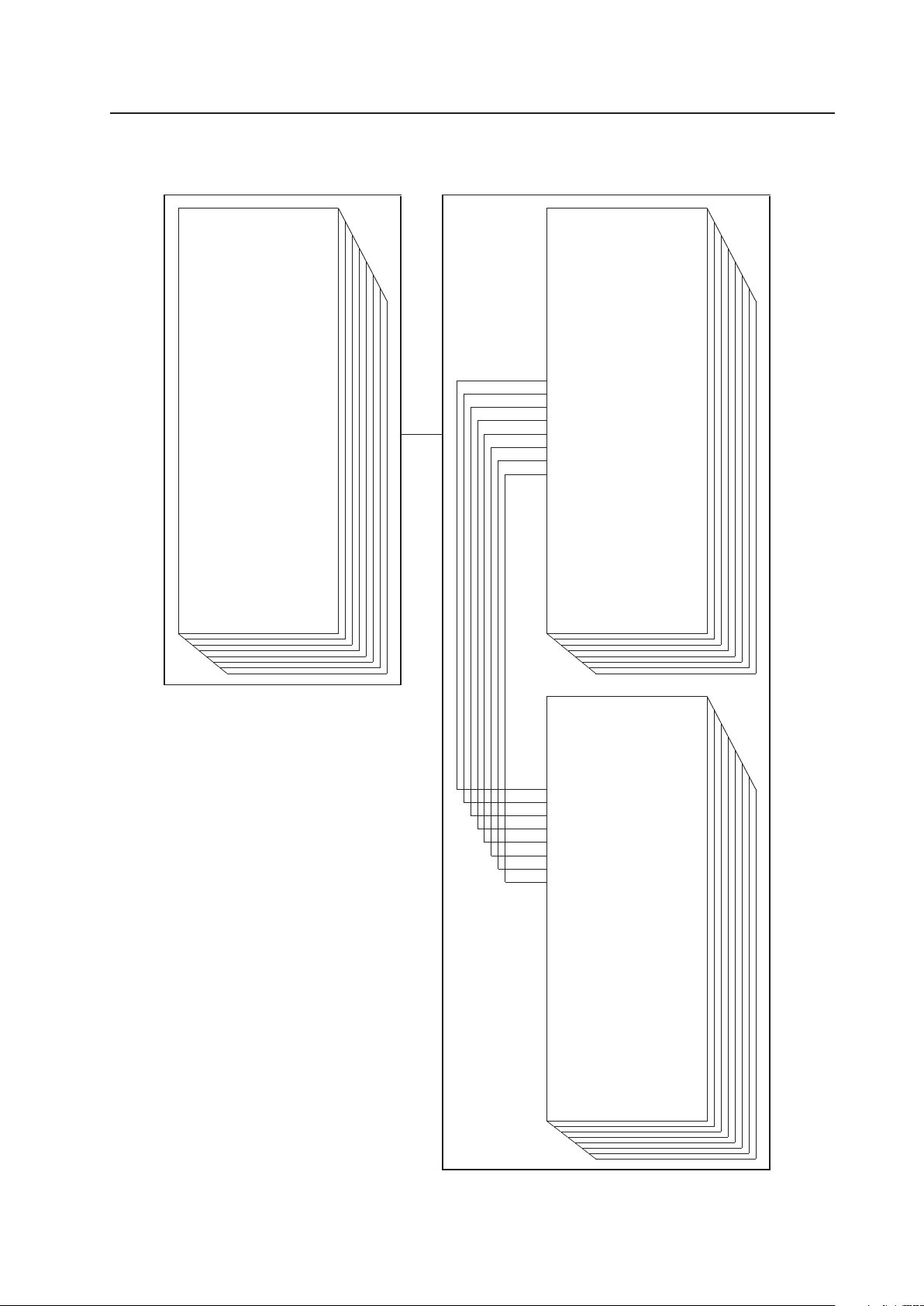
189
Integrator Mode
7 INPUT2
¥CONTRAST
¥BRIGHTNESS
¥H. ENHANCE !
¥V. ENHANCE !
¥COLOR
★
¥TINT
★
¥SHARPNESS
★
¥H. POSITION
¥V. POSITION
¥COLOR TEMP.
★
¥DNR
★
¥MPEG NR
★
¥CTI
★
¥PURECINEMA
★
¥COLOR DECODING
★
INPUT2–SIGNAL#1
¥CONTRAST
¥BRIGHTNESS
¥H. ENHANCE !
¥V. ENHANCE !
¥COLOR
★
¥TINT
★
¥SHARPNESS
★
¥C. DETAIL RED
¥C. DETAIL YELLOW
¥C. DETAIL GREEN
¥C. DETAIL CYAN
¥C. DETAIL BLUE
¥C. DETAIL MAGENTA
¥R. HIGH
¥G. HIGH
¥B. HIGH
¥R. LOW
¥G. LOW
¥B. LOW
¥H. POSITION
¥V. POSITION
¥H. SIZE
¥V. SIZE
¥GAMMA
INPUT2–SIGNAL##A
(COLOR MODE; NORMAL)
¥CONTRAST
¥BRIGHTNESS
¥H. ENHANCE !
¥V. ENHANCE !
¥COLOR
★
¥TINT
★
¥SHARPNESS
★
¥C. DETAIL RED
¥C. DETAIL YELLOW
¥C. DETAIL GREEN
¥C. DETAIL CYAN
¥C. DETAIL BLUE
¥C. DETAIL MAGENTA
¥R. HIGH
¥G. HIGH
¥B. HIGH
¥R. LOW
¥G. LOW
¥B. LOW
¥H. POSITION
¥V. POSITION
¥H. SIZE
¥V. SIZE
¥GAMMA
INPUT2–SIGNAL##A
(COLOR MODE; STUDIO)
MENU INTEGRATOR
★: Applicable only when a PDA-5003/PDA-
5004 is installed and when inputting/
adjusting a video signal.
! : Applicable only when inputting/adjusting a
PC signal.
190
Integrator Mode
¥CONTRAST
¥BRIGHTNESS
¥COLOR
¥TINT
¥SHARPNESS
¥H. POSITION
¥V. POSITION
¥COLOR TEMP.
¥DNR
¥MPEG NR
¥CTI
¥PURECINEMA
INPUT3–SIGNAL#1
¥CONTRAST
¥BRIGHTNESS
¥COLOR
¥TINT
¥SHARPNESS
¥C. DETAIL RED
¥C. DETAIL YELLOW
¥C. DETAIL GREEN
¥C. DETAIL CYAN
¥C. DETAIL BLUE
¥C. DETAIL MAGENTA
¥R. HIGH
¥G. HIGH
¥B. HIGH
¥R. LOW
¥G. LOW
¥B. LOW
¥H. POSITION
¥V. POSITION
¥H. SIZE
¥V. SIZE
¥GAMMA
INPUT3–SIGNAL##A
(COLOR MODE; NORMAL)
¥CONTRAST
¥BRIGHTNESS
¥COLOR
¥TINT
¥SHARPNESS
¥C. DETAIL RED
¥C. DETAIL YELLOW
¥C. DETAIL GREEN
¥C. DETAIL CYAN
¥C. DETAIL BLUE
¥C. DETAIL MAGENTA
¥R. HIGH
¥G. HIGH
¥B. HIGH
¥R. LOW
¥G. LOW
¥B. LOW
¥H. POSITION
¥V. POSITION
¥H. SIZE
¥V. SIZE
¥GAMMA
INPUT3–SIGNAL##A
(COLOR MODE; STUDIO)
MENU INTEGRATOR
(INPUT3 is effective only when a PDA-5003/PDA-
5004 is installed.)
Note
When a PDA-5003/PDA-5004 is installed, the
values are stored in memory for both a 50 Hz
video signal and 60 Hz video signal.
7 INPUT3
191
Integrator Mode
7 INPUT4
¥CONTRAST
¥BRIGHTNESS
¥COLOR
¥TINT
¥SHARPNESS
¥H. POSITION
¥V. POSITION
¥COLOR TEMP.
¥DNR
¥MPEG NR
¥CTI
¥PURECINEMA
INPUT4–SIGNAL#1
¥CONTRAST
¥BRIGHTNESS
¥COLOR
¥TINT
¥SHARPNESS
¥C. DETAIL RED
¥C. DETAIL YELLOW
¥C. DETAIL GREEN
¥C. DETAIL CYAN
¥C. DETAIL BLUE
¥C. DETAIL MAGENTA
¥R. HIGH
¥G. HIGH
¥B. HIGH
¥R. LOW
¥G. LOW
¥B. LOW
¥H. POSITION
¥V. POSITION
¥H. SIZE
¥V. SIZE
¥GAMMA
INPUT4–SIGNAL##A
(COLOR MODE; NORMAL)
¥CONTRAST
¥BRIGHTNESS
¥COLOR
¥TINT
¥SHARPNESS
¥C. DETAIL RED
¥C. DETAIL YELLOW
¥C. DETAIL GREEN
¥C. DETAIL CYAN
¥C. DETAIL BLUE
¥C. DETAIL MAGENTA
¥R. HIGH
¥G. HIGH
¥B. HIGH
¥R. LOW
¥G. LOW
¥B. LOW
¥H. POSITION
¥V. POSITION
¥H. SIZE
¥V. SIZE
¥GAMMA
INPUT4–SIGNAL##A
(COLOR MODE; STUDIO)
MENU INTEGRATOR
(INPUT4 is effective only when a PDA-5003/
PDA-5004 is installed.)
Note
When a PDA-5003/PDA-5004 is installed, the
values are stored in memory for both a 50 Hz
video signal and 60 Hz video signal.
192
Integrator Mode
7 INPUT5
¥CONTRAST
¥BRIGHTNESS
¥R. LEVEL !
¥G. LEVEL !
¥B. LEVEL !
¥H. ENHANCE !
¥V. ENHANCE !
¥COLOR
★
¥TINT
★
¥SHARPNESS
★
¥H. POSITION
¥V. POSITION
¥CLOCK !
¥PHASE !
¥COLOR TEMP.
★
¥DNR
★
¥MPEG NR
★
¥CTI
★
¥PURECINEMA
★
¥COLOR DECODING
★
INPUT5–SIGNAL#1
¥CONTRAST
¥BRIGHTNESS
¥H. ENHANCE !
¥V. ENHANCE !
¥COLOR
★
¥TINT
★
¥SHARPNESS
★
¥C. DETAIL RED
¥C. DETAIL YELLOW
¥C. DETAIL GREEN
¥C. DETAIL CYAN
¥C. DETAIL BLUE
¥C. DETAIL MAGENTA
¥R. HIGH
¥G. HIGH
¥B. HIGH
¥R. LOW
¥G. LOW
¥B. LOW
¥H. POSITION
¥V. POSITION
¥CLOCK !
¥PHASE !
¥H. SIZE
¥V. SIZE
¥GAMMA
INPUT5–SIGNAL##A
(COLOR MODE; NORMAL)
¥CONTRAST
¥BRIGHTNESS
¥H. ENHANCE !
¥V. ENHANCE !
¥COLOR
★
¥TINT
★
¥SHARPNESS
★
¥C. DETAIL RED
¥C. DETAIL YELLOW
¥C. DETAIL GREEN
¥C. DETAIL CYAN
¥C. DETAIL BLUE
¥C. DETAIL MAGENTA
¥R. HIGH
¥G. HIGH
¥B. HIGH
¥R. LOW
¥G. LOW
¥B. LOW
¥H. POSITION
¥V. POSITION
¥CLOCK !
¥PHASE !
¥H. SIZE
¥V. SIZE
¥GAMMA
INPUT5–SIGNAL##A
(COLOR MODE; STUDIO)
MENU INTEGRATOR
(INPUT5 is effective only when a PDA-5003/
PDA-5004 is installed.)
★: Applicable only when inputting/adjusting a
video signal.
! : Applicable only when inputting/adjusting a PC
signal.

193
5.5 RS-232C Adjustment
This display has an RS-232C terminal. It is possible to use a PC to make various adjustments and settings.
5.5.1 About the RS-232C Adjustment
Adjustments using the RS-232C:
• The adjustments are written to the same memory area as for the integrator mode (refer to section 5.4.4, “PICTURE,
White Balance and SCREEN Position Adjustment Values Memory Area Tables” (pg. 188)).
(1) Assign an ID before using the RS-232C adjustment. Include the panel ID in the RS-232C command.
For details, refer to section 5.5.2, “Interface” (pg. 194).
(2) Of the adjustment values and setting items set by RS-232C commands, there are some items that are
stored in memory and some that are not. For details, refer to section 5.5.5, “List of RS-232C Commands”
(pg. 198). Also, when storing values in “last” memory, the conditions described in section 5.1.5, “Last
Memory” (pg. 111), must be satisfied.
(3) <OSDS00>/<OSDS01> (OSD display disable/enable setting)
Regardless of the setting, the following items can be displayed.
• Menu display (menu mode, integrator mode)
• Warnings before Auto Power OFF or Power Management operation
• Warning of high temperature inside the panel
• Display announcing that the FUNCTIONAL LOCK is set and the FUNCTIONAL LOCK setting display
• Display call (including holding a button down)
(4) When using RS-232C commands, control the input signal as well as the power. If the power is ON when
there is no signal, the display continues to have a weak discharge. This activity can affect the life of the
display.
Notes
RS-232C Adjustment
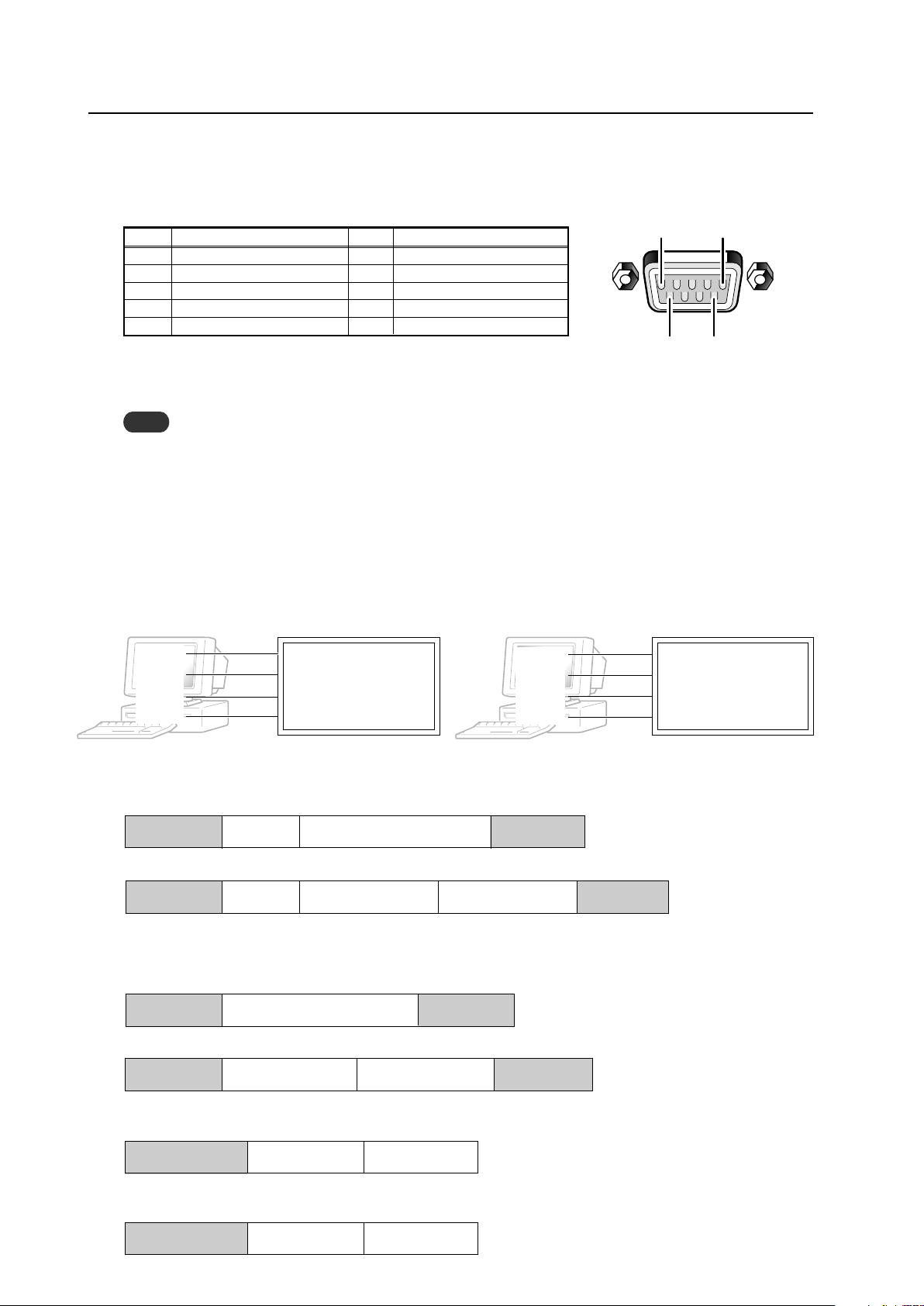
194
RS-232C Adjustment
5.5.2 Interface
1) Connector
D-sub 9 pins (male/straight)
2) Pin layout
3) Baud Rate
9600 bps (standard)
(switch-able to 1200, 2400, 4800, 19200, 38400 bps)
Note
The baud rate of this display should be set to match the baud rate of the PC.
Also, when the RS-232C cable is extended over a long distance, use a slower baud rate.
4) Data format
Start bit: 1 bit
Data bit: 8 bit
Parity: no
Stop bit: 1 bit
5) Connection
6) Protocol
From the PC to the display
Straight Cable
* D-sub 9-pin/D-sub 25-pin conversion tables are now available on the market.
Control PC Plasma Display Control PC Plasma Display
(with D25 serial port ) (PDP-425CMX/PDP-42MXE10) (with D9 serial port) (PDP-425CMX/PDP-42MXE10)
2
2
3
2
3
2
RXD 3 2 TXD RXD 2 2 TXD
TXD 2 3 RXD TXD 3 3 RXD
CTS 5 8 RTS CTS 8 8 RTS
GND 7 5 GND GND 5 5 GND
5
96
1
Pin No.
Signal
1 NC (not connected)
2 TxD (Transmit Data)
3 RxD (Receive Data)
4 NC (not connected)
5 GND
Pin No.
Signal
6 NC (not connected)
7 NC (not connected)
8 RTS (Request To Send)
9 NC (not connected)
(1) Sending one command at a time:
STX (02 hex) ID (2 Byte) COMMAND (3 Byte or 6 Byte) ETX (03 hex)
(2) Sending numerical direct commands:
STX (02 hex) ID (2 Byte) COMMAND (3 Byte) ARGUMENT (3 Byte) ETX (03 hex)
ID, COMMAND, ARGUMENT are transmitted as ASCII characters.
From the display to a PC
(1) Echo back (Normal response)
Command received and returned but the ID is not returned.
STX (02 hex) COMMAND (3 Byte or 6 Byte) ETX (03 hex)
Received command is a numerical direct effect command and numerical data is returned:
STX (02 hex) COMMAND (3 Byte) ARGUMENT (3 Byte) ETX (03 hex)
(2) Error (Abnormal response)
Received command is a non-corresponding command, ‘ERR’ is returned:
STX (02 hex) ERR (3 Byte) ETX (03 hex)
Received command cannot be processed (when PON is received when the power is already ON, etc.), ‘XXX’ is
returned:
STX (02 hex) XXX (3 Byte) ETX (03 hex)
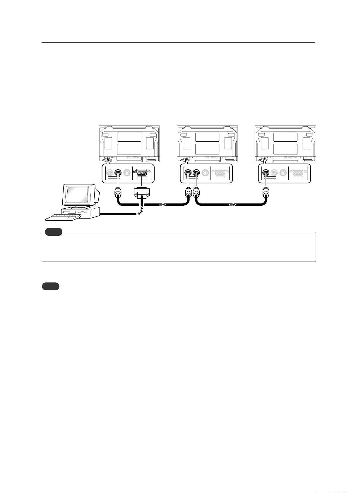
195
RS-232C Adjustment
5.5.3 Combination Connection
When controlling/adjusting panels, it is convenient to connect several displays to one PC.
By performing a combination connection and assigning IDs to the panels, it is possible to control and adjust several
displays at the same time or separately.
Connection method:
Connect the panels as shown in the figure below.
Only the combination IN terminal or the RS-232C terminal can be used at the same time. Connecting them at the
same time could cause errors. Also, do not pair combination IN terminals or combination OUT terminals. Doing so
could cause communication to fail.
It is possible to use a general-purpose mini DIN 6-pin (straight) cable for the combination cable.
Note
To output RS-232C signals from the combination OUT terminal, an ID must be assigned.
For details, refer to section, 5.5.4, “ID Assignment” (pg. 196).
Note
IN OUT
RS-232C
IN OUT IN OUT
RS-232C
COMBINATION
RS-232C
COMBINATIONCOMBINATION
First Panel
Second Panel Third Panel
Combination cable
Combination cable
PC
OUT
IN
IN
OUT
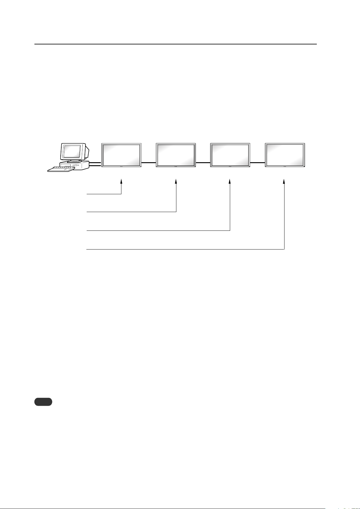
196
RS-232C Adjustment
5.5.4 ID Assignment
The ID is assigned from the PC.
Commands: <IDC> (ID CLEAR) ........ Clears the assigned ID
<IDS> (ID SET) ............. Assigns an ID
IDS is only effective when an ID is not assigned.
IDs are assigned starting from the panel closest to the PC.
Example: Case of 4 displays (assigning IDs with the PC for the first time)
First, connect an RS-232C and combination cables. (Refer to section 5.5.3, “Combination Connection” (pg.
195).)
By sending RS-232C commands in this order, it is possible to assign an ID for each panel.
When a panel has a PC-assigned ID, it can only receive commands containing the ID. Assign an ID before sending a
command.
Characters that can be used for an ID include, 0 - 9 and A - F (there is not distinction between upper case and lower case
letters).
An ∗ (asterisk) can be used as follows:
<∗∗IDC>: Clear the IDs assigned for all panels
<2∗IN1>: The input for which the first digit is 2 is set to INPUT1
Precautions when assigning IDs
Panels connected after a display’s ID has been cleared cannot be operated with RS-232C commands.
When the <∗∗IDC> command is sent, the IDs for all the sets from Set #1 to Set #4 are cleared. Only the first panel,
which is directly connected to the PC, can be controlled.
Send the command <01 IDS> to control the next panel. Continue setting IDs in this way for the remaining panels to
once again control the displays.
Note
When the IDs are set, when one or both of the IDs before a command is sent from the PC is an ∗, there is no echo.
When sending more commands, wait 6 seconds before sending the next command.
Example) When ∗∗OOO and ∗1OOO or 1∗OOO (OOO is the command) are sent from the PC, operation is performed
but there is no echo.
Set #4
ID = 04
Set #1 Set #2 Set #3
ID = 01
Sent commands:
1 <01 IDS>
2 <02 IDS>
3 <03 IDS>
4 <04 IDS>
ID = 02 ID = 03
PC
OUT IN OUT IN OUT IN
‘
‘
‘
±
RS-232C connection
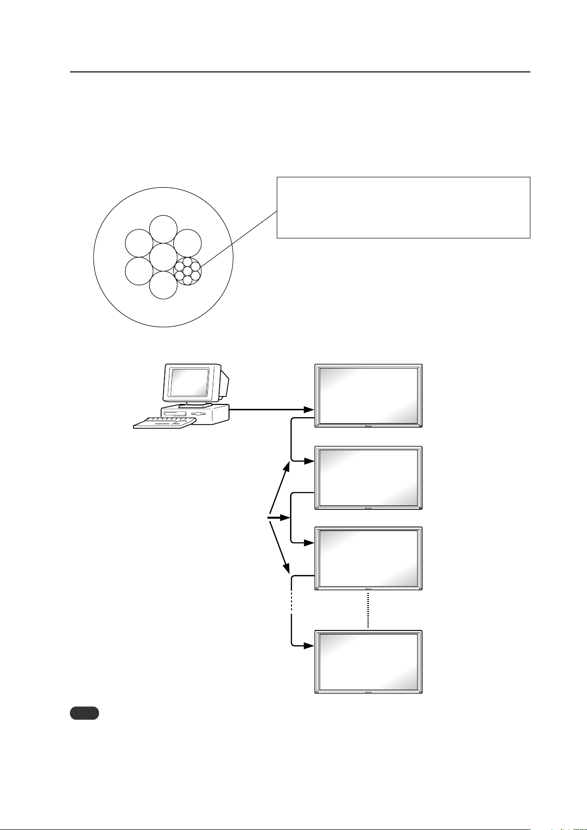
197
Under the connection conditions shown below, use a combination cable for up to 16 panels.
Conditions: 1 Length of RS-232C cable connecting PC to PDP-425CMX/PDP-42MXE10: 5 m
2 Combination cable length: 5 m each
3 Wire specifications for linking cable: Mini Din 6-pin straight (7 strand cable)
For 1 strand, suitable for AWG28:
Cross-section area = 0.08 mm
2
≠
7 strands × π r
2
= 7 × 3.14 × 0.06
2
= 0.079 mm
2
≠ 0.08 mm
2
Note
For details on the number of displays that can be connected in series using the video OUT terminal (INPUT1, 4), refer to
section 2.3, “Controls and Connectors” (pg. 10).
PC
RS-232C
Combination cable 5m
PDP-425CMX
PDP-42MXE10
1
2
3
#
OUT
IN
OUT
IN
OUT
IN
5m
RS-232C Adjustment
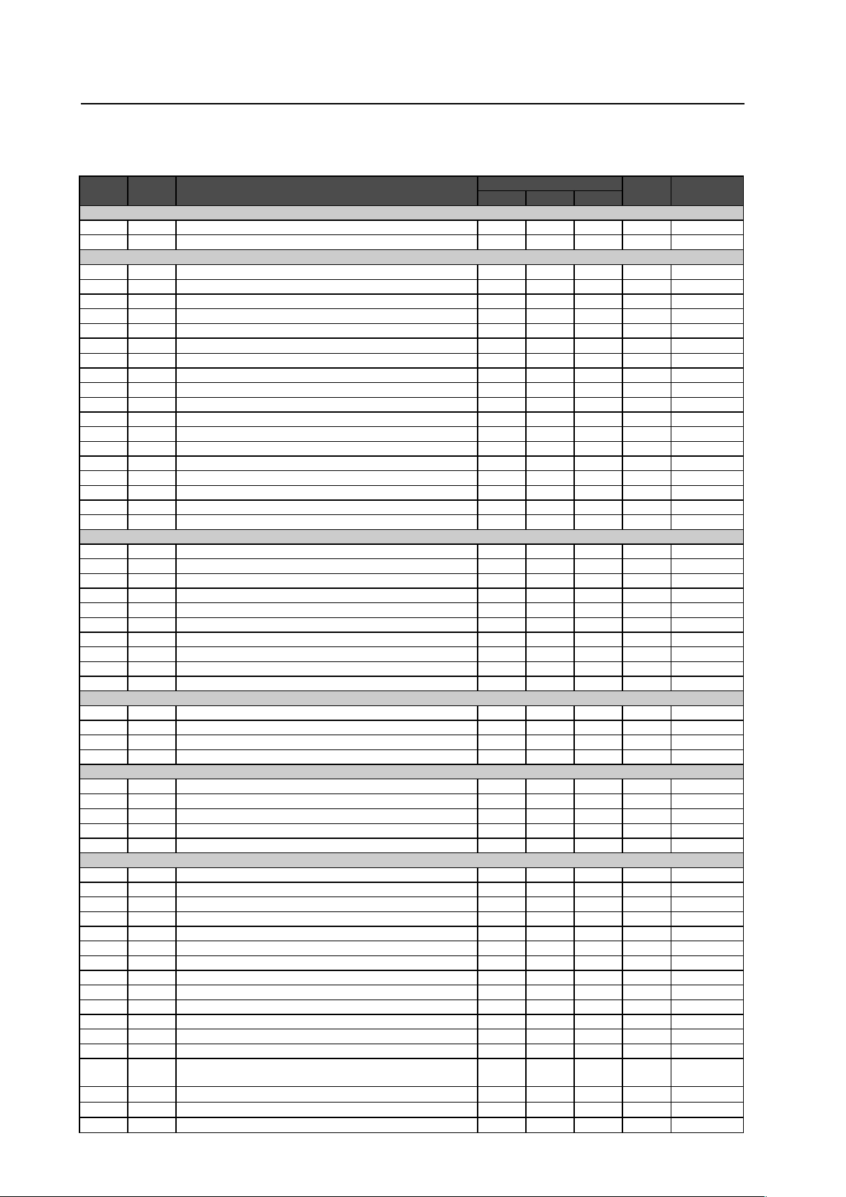
198
RS-232C Adjustment
5.5.5
List of RS-232C Commands
(Command 434CMX = Command 43MXE1 / Command 425CMX = Command 42MXE10)
7
Normal Operation Related Commands
Command
434CMX
Command
425CMX
Function
Number direct Last
memory
Comment
Effective Minimum Maximum
POWER
POF
+
Turns the power OFF.
�
PON
+
Turns the power ON.
�
INPUT SELECT
INP
+
Displays the present input.
INPS01
+
Switches the main screen to INPUT1.
�
INPS02
+
Switches the main screen to INPUT2.
�
INPS03
+
Switches the main screen to INPUT3.
�
INPS04
+
Switches the main screen to INPUT4.
�
INPS05
+
Switches the main screen to INPUT5.
�
IN1
+
Switches the main screen to INPUT1.
�
IN2
+
Switches the main screen to INPUT2.
�
IN3
+
Switches the main screen to INPUT3.
�
IN4
+
Switches the main screen to INPUT4.
�
IN5
+
Switches the main screen to INPUT5.
�
SSIS01
+
Switches the sub screen to INPUT1.
�
SSIS02
+
Switches the sub screen to INPUT2.
�
SSIS03
+
Switches the sub screen to INPUT3.
�
SSIS04
+
Switches the sub screen to INPUT4.
�
SSIS05
+
Switches the sub screen to INPUT5.
�
– SWM Outputs main input to the full screen.
�
New
– SWS Outputs sub input to the full screen.
�
New
SCREEN SIZE
AST
+
Executes auto-setup.
�
SZM
+
Displays the present screen size.
SZMS00
+
Sets SCREEN SIZE to DOT BY DOT.
�
SZMS01
+
Sets SCREEN SIZE to 4 :3.
�
SZMS02
+
Sets SCREEN SIZE to FULL.
�
SZMS03
+
Sets SCREEN SIZE to ZOOM.
�
SZMS05
+
Sets SCREEN SIZE to WIDE.
�
– SZMS06 Sets SCREEN SIZE to 14:9.
�
New
SZMS09
+
Sets SCREEN SIZE to UNDERSCAN.
�
– SZMS10 Sets SCREEN SIZE to 2.35:1.
�
New
VIDEO
MTN PMTS00 Turns video mute to OFF.
�
MTY PMTS01 Turns video mute to ON.
�
SLN STLS00 Cancels FREEZE.
�
SLY STLS01 Sets FREEZE.
�
AUDIO
VOL
+
Adjusts audio volume.
�
000 042
�
AMN AMTS00 Turns audio mute to OFF.
�
New
AMY AMTS01 Turns audio mute to ON.
�
New
– AUSS01 Sets the audio source to main.
�
New
– AUSS02 Sets the audio source to sub.
�
New
MULTI SCREEN
MSC
+
Displays the present multi-screen.
– MSCS00 Turns MULTI SCREEN to OFF.
�
– MSSS01 Sets the PinP subscreen size to 1.
�
New
– MSSS02 Sets the PinP subscreen size to 2.
�
New
– MSSS03 Sets the PinP subscreen size to 3.
�
New
– MSSS04 Sets the PinP subscreen size to 4.
�
New
MST
+
Displays the present multi-screen type.
MSTS01
+
Sets the MULTI SCREEN to 2 SCREEN (side by side 1)
�
MSTS02
+
Sets the MULTI SCREEN to PinP (lower right).
�
MSTS03
+
Sets the MULTI SCREEN to PinP (upper right).
�
MSTS04
+
Sets the MULTI SCREEN to PinP (upper left).
�
MSTS05
+
Sets the MULTI SCREEN to PinP (lower left).
�
MSTS06
+
Sets the MULTI SCREEN to PoutP (side by side, 2-L).
�
– MSTS08
Sets MULTI SCREEN to SWAP (switches between main and sub
screens).
�
New
– MSTS09
Sets MULTI SCREEN to PoutP (side by side 2-R).
�
New
– MSTS10
Sets MULTI SCREEN to 2-SCREEN (side by side 3).
�
New
– MSTS11
Sets MULTI SCREEN to PoutP (side by side 4-L).
�
New
199
RS-232C Adjustment
Command
434CMX
Command
425CMX
Function
Number direct Last
memory
Comment
Effective Minimum Maximum
– MSTS12
Sets MULTI SCREEN to PoutP (side by side 4-R).
�
New
SSI
+
Displays the present input to the SUB Screen.
FUNCTIONAL LOCK
FCL
+
Displays the present set value of the FUNCTIONAL LOCK.
FCLS00
+
Cancels FUNCTIONAL LOCK.
�
FCLS01
+
Prohibits operation of buttons on the display.
�
FCLS02
+
Prohibits operation of buttons on the remote control.
�
FCLS03
+
Prohibits operation of buttons on the display/remote control.
�
FCLS04
+
Sets the memory lock
�
OSD
DOF
+
Turns off the OSD display that is now displayed.
7
“MENU”–“SET UP” related commands
Command
434CMX
Command
425CMX
Function
Number direct Last
memory
Comment
Effective Minimum Maximum
COLOR TEMP.
CTP
+
Displays the present set value of the color temperature.
CTPS01
+
Sets the color temperature to LOW.
�
CTPS02
+
Sets the color temperature to MID LOW.
�
CTPS03
+
Sets the color temperature to MIDDLE.
�
CTPS04
+
Sets the color temperature to MID HIGH.
�
CTPS05
+
Sets the color temperature to HIGH.
�
DNR
DNR
+
Displays the present set value of the DNR.
DNRS00
+
Sets digital NR to OFF.
�
DNRS01
+
Sets digital NR to LOW.
�
DNRS02
+
Sets digital NR to MIDDLE.
�
DNRS03
+
Sets digital NR to HIGH.
�
MPEG NR
MNR
+
Displays the present set value of the MPEG NR.
MNRS00
+
Sets MPEG NR to OFF.
�
MNRS01
+
Sets MPEG NR to LOW.
�
MNRS02
+
Sets MPEG NR to MIDDLE.
�
MNRS03
+
Sets MPEG NR to HIGH.
�
CTI
CTR
+
Displays the present set value of CTI.
CTRS00
+
Sets CTI to OFF.
�
CTRS01
+
Sets CTI to ON.
�
PURE CINEMA
PUC
+
Displays the present set value of PURE CINEMA.
PUCS00
+
Sets PURE CINEMA to OFF.
�
PUCS01
+
Sets PURE CINEMA to STANDARD.
�
COLOR DECORDING
MCD
+
Displays the present color decoding.
MCDS01
+
Sets COLOR DECORDING to RGB (VIDEO).
�
MCDS02
+
Sets COLOR DECORDING to COMPONENT1 (YCbCr).
�
MCDS03
+
Sets COLOR DECORDING to COMPONENT2 (YPbPr).
�
COLOR SYSTEM
CLS
+
Displays the present set value of the color system.
CLSS01
+
Sets color system to AUTO.
�
CLSS02
+
Sets color system to NTSC.
�
CLSS03
+
Sets color system to PAL.
�
CLSS04
+
Sets color system to SECAM.
�
CLSS05
+
Sets color system to 4.43NTSC.
�
CLSS06
+
Sets color system to PAL M.
�
CLSS07
+
Sets color system to PAL N.
�
SIGNAL FORMAT
SFT
+
Displays the present set value of the SIGNAL FORMAT.
SFTS01
+
Sets SIGNAL FORMAT to Type1.
�
Operation change
SFTS02
+
Sets SIGNAL FORMAT to Type2.
�
Operation change
SFTS03
+
Sets SIGNAL FORMAT to Type3.
�
Operation change
SFTS04
+
Sets SIGNAL FORMAT to Type4.
�
Operation change
– SFTS05 Sets SIGNAL FORMAT to Type5.
�
New
– SFTS06 Sets SIGNAL FORMAT to Type6.
�
New
200
RS-232C Adjustment
Command
434CMX
Command
425CMX
Function
Number direct Last
memory
Comment
Effective Minimum Maximum
– SFTS07 Sets SIGNAL FORMAT to Type7.
�
New
– SFTS08 Sets SIGNAL FORMAT to Type8.
�
New
– SFTS10 Sets SIGNAL FORMAT to AUTO.
�
New
DVI
– DSGS01 Sets the DVI connection signal to PC.
�
New
– DSGS02 Sets the DVI connection signal to STB/DVD.
�
New
– DBLS01 Sets the DVI BLACK LEVEL to LOW.
�
New
– DBLS02 Sets the DVI BLACK LEVEL to HIGH.
�
New
7
“MENU”–“OPTION” related commands
Command
434CMX
Command
425CMX
Function
Number direct Last
memory
Comment
Effective Minimum Maximum
ENERGY SAVE
ESV
+
Displays the present set value of ENERGY SAVE.
ESVS00
+
Sets ENERGY SAVE to standard.
�
ESVS01
+
Sets ENERGY SAVE to save energy.
�
ESVS02
+
Sets ENERGY SAVE to fi xed brightness.
�
ESVS03
+
Sets ENERGY SAVE to mode 3 (long service life).
�
ESVS04
+
Sets ENERGY SAVE to AUTO.
�
TIMER
– TSMS00 Turns summer time to OFF.
�
New
– TSMS01 Turns summer time to ON.
�
New
– TPH Sets the hour of the present time.
�
000 023
�
New
– TPM Sets the minute of the present time.
�
000 059
�
New
– TPW Sets the day of week of the present time.
�
001 007
�
New
– TPTS00 Sets PROGRAM TIMER to OFF.
�
New
– TPTS01 Sets PROGRAM TIMER to ON.
�
New
ORBITER
OMN ORBS00 Sets the ORBITER to OFF.
�
OMY ORBS01 Sets the ORBITER to ON (AUTO1).
�
– ORBS02 Sets the ORBITER to ON (AUTO2).
�
New
– ORBS03 Sets the ORBITER to ON (AUTO3).
�
New
SOFT FOCUS
– SOFS00 Sets SOFT FOCUS to OFF.
�
New
– SOFS01 Sets SOFT FOCUS to 1.
�
New
– SOFS02 Sets SOFT FOCUS to 2.
�
New
– SOFS03 Sets SOFT FOCUS to 3.
�
New
– SOFS04 Sets SOFT FOCUS to 4.
�
New
SUB SCREEN FREEZE
– SSTS00 Sets SUB SCREEN FREEZE to OFF.
�
New
– SSTS01 Sets SUB SCREEN FREEZE to SIDE BY SIDE.
�
New
– SSTS02 Sets SUB SCREEN FREEZE to PinP.
�
New
201
RS-232C Adjustment
7
“INTEGRATOR”–“PICTURE” related commands
Command
434CMX
Command
425CMX
Function
Number direct Last
memory
Comment
Effective Minimum Maximum
VIDEO QUALITY
CNT
+
Adjusts the contrast.
�
000 255
�
BRT
+
Adjusts the brightness.
�
000 255
�
ENH
+
Adjusts the horizontal enhance.
�
000 015
�
ENV
+
Adjusts the vertical enhance.
�
000 015
�
COL
+
Adjusts the color.
�
000 127
�
TNT
+
Adjusts the tint.
�
000 060
�
SHP
+
Adjusts the sharpness.
�
000 015
�
WHITE BALANCE
RHI
+
Adjusts R.HIGH of the white balance.
�
000 255
�
GHI
+
Adjusts G.HIGH of the white balance.
�
000 255
�
BHI
+
Adjusts B.HIGH of the white balance.
�
000 255
�
GLW
+
Adjusts G.LOW of the white balance.
�
000 255
�
RLW
+
Adjusts R.LOW of the white balance.
�
000 255
�
BLW
+
Adjusts B.LOW of the white balance.
�
000 255
�
COLOR DETAIL
CGR
+
Adjusts color detail red.
�
000 060
�
CGY
+
Adjusts color detail yellow.
�
000 060
�
CGG
+
Adjusts color detail green.
�
000 060
�
CGC
+
Adjusts color detail cyan.
�
000 060
�
CGB
+
Adjusts color detail blue.
�
000 060
�
CGM
+
Adjusts color detail magenta.
�
000 060
�
GAMMA
GRA
+
Displays the present set value of gradation.
– GRAS18 Sets gradation GAMMA 1.8.
�
New
– GRAS19 Sets gradation GAMMA 1.9.
�
New
– GRAS20 Sets gradation GAMMA 2.0.
�
New
– GRAS21 Sets gradation GAMMA 2.1.
�
New
– GRAS22 Sets gradation GAMMA 2.2.
�
New
– GRAS23 Sets gradation GAMMA 2.3.
�
New
– GRAS24 Sets gradation GAMMA 2.4.
�
New
PRESET
STD
+
Restores the PICTURE, W/B adjustment value of the integrator to the initial
values.
�
7
“INTEGRATOR”–“SCREEN” related commands
Command
434CMX
Command
425CMX
Function
Number direct Last
memory
Comment
Effective Minimum Maximum
POSITION
HPS
+
Adjusts the horizontal position.
�
000 255
�
VPS
+
Adjusts the vertical position.
�
000 255
�
CLOCK/PHASE
CFR
+
Adjusts the CLOCK (PLL frequency).
�
000 255
�
CPH
+
Adjusts the PHASE (PLL phase).
�
000 031
�
SIZE
HSI
+
Adjusts the horizontal size.
�
000 064
�
VSI
+
Adjusts the vertical size.
�
000 064
�
PRESET
FRP
+
Restores the SCREEN adjustment value of the integrator to the initial
values.
�
7
“INTEGRATOR”–“SET UP” related commands
Command
434CMX
Command
425CMX
Function
Number direct Last
memory
Comment
Effective Minimum Maximum
SUB VOLUME
SVL
+
Adjusts the SUB VOLUME.
�
000 020
�
202
RS-232C Adjustment
7
“INTEGRATOR”–“OPTION” related commands
Command
434CMX
Command
425CMX
Function
Number direct Last
memory
Comment
Effective Minimum Maximum
SCREEN MASK
FMK
+
Displays the present set value of SCREEN MASK.
FMKS00
+
Sets SCREEN MASK to OFF.
�
FMKS02
+
Sets SCREEN MASK to inverse (negative – positive reversed).
�
FMKS03
+
Sets SCREEN MASK to white mask.
�
FMKS04
+
Sets SCREEN MASK to red mask.
�
FMKS05
+
Sets SCREEN MASK to green mask.
�
FMKS06
+
Sets SCREEN MASK to blue mask.
�
FMKS07
+
Sets SCREEN MASK to yellow mask.
�
SIDE MASK
RSL
+
Adjusts side mask RED.
�
000 255
�
GSL
+
Adjusts side mask GREEN.
�
000 255
�
BSL
+
Adjusts side mask BLUE.
�
000 255
�
VIDEO WALL
MGF
+
Displays the set value of VIDEO WALL.
MGFS00
+
Sets VIDEO WALL to OFF.
�
– MGFS11 Sets VIDEO WALL to DIVIDER:1.
�
New
– MGFS12 Sets VIDEO WALL to DIVIDER:4.
�
New
– MGFS13 Sets VIDEO WALL to DIVIDER:9.
�
New
– MGFS14 Sets VIDEO WALL to DIVIDER:16.
�
New
– MGFS15 Sets VIDEO WALL to DIVIDER:25.
�
New
MGP
+
Displays the present VIDEO WALL (accounting/not accounting for expanded
position/joints) setting.
MGPSnn
+
nn=01 to 04: Sets display position during DIVIDER=4 (not accounting for joints).
�
nn=05 to 08: Sets display position during DIVIDER=4 (accounting for joints).
�
nn=10 to 18: Sets display position during DIVIDER=9 (not accounting for joints).
�
New
nn=20 to 28: Sets display position during DIVIDER=9 (accounting for joints).
�
New
nn=30 to 3F: Sets display position during DIVIDER=16 (not accounting for joints).
�
New
nn=40 to 4F: Sets display position during DIVIDER=16 (accounting for joints).
�
New
nn=50 to 68: Sets display position during DIVIDER=25 (not accounting for joints).
�
New
nn=70 to 88: Sets display position during DIVIDER=25 (accounting for joints).
�
New
– IDA Executes AUTO ID setting.
�
New
– PDES00 Sets POWER ON DELAY mode to OFF.
�
New
– PDES01
Sets POWER ON DELAY mode to ON (other than cases used for a higher
than 16 screen system) or mode 1 (used for a higher than 16 screen system).
�
New
– PDES02 Sets POWER ON DELAY mode 2 (used for a higher than 16 screen system).
�
New
– LNKS00 Sets ABL link to OFF.
�
New
– LNKS01 Sets ABL link to ON.
�
New
RS-232C
BRA
+
Displays the present set value of baud rate.
BRAS01
+
Sets the RS-232C baud rate to 1200 bps.
�
BRAS02
+
Sets the RS-232C baud rate to 2400 bps.
�
BRAS03
+
Sets the RS-232C baud rate to 4800 bps.
�
BRAS04
+
Sets the RS-232C baud rate to 9600 bps.
�
BRAS05
+
Sets the RS-232C baud rate to 19200 bps.
�
BRAS06
+
Sets the RS-232C baud rate to 38400 bps.
�
ID NUMBER
IDC
+
Clears the ID number.
�
IDS
+
Sets the ID number.
�
FAN
FCM
+
Maximizes fan rotation control.
�
FCA
+
Automates fan rotation control.
�
OSD
DIN OSDS00 Sets OSD display to OFF.
�
DIY OSDS01 Sets OSD display to ON.
�
– OSSS01 Displays expanded OSD.
�
New
– OSSS02 Displays contracted OSD.
�
New
– OSAS01 Sets the OSD display angle to horizontal.
�
New
– OSAS02 Sets the OSD display angle to vertical.
�
New
FRONT INDICATOR
LEN LESS00 Sets the FRONT INDICATOR to OFF.
�
LEY LESS01 Sets the FRONT INDICATOR to ON.
�
COLOR MODE
CM1 CLMS00 Sets the COLOR MODE to NORMAL.
�
CM2 CLMS01 Sets the COLOR MODE to STUDIO.
�
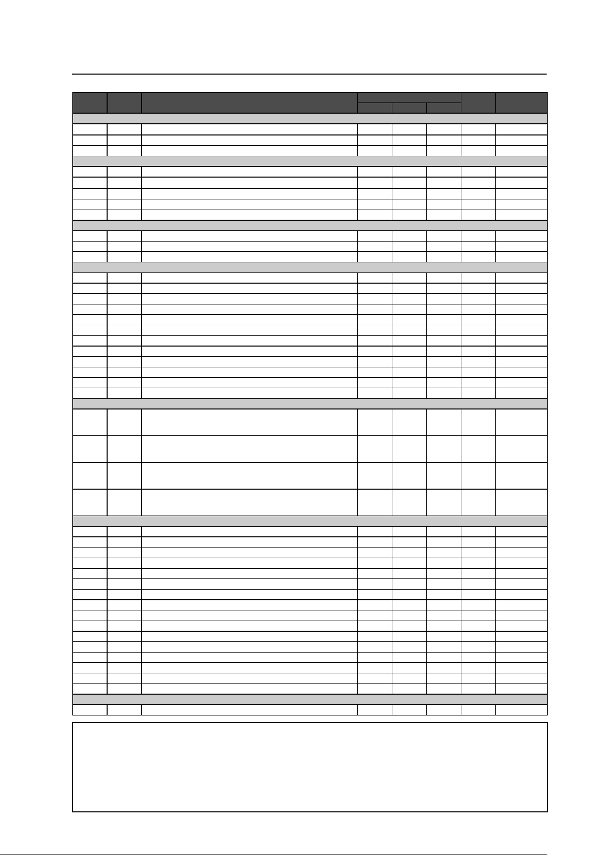
203
RS-232C Adjustment
Command
434CMX
Command
425CMX
Function
Number direct Last
memory
Comment
Effective Minimum Maximum
UNDER SCAN
USCS00
+
Sets the UNDERSCAN setting to OFF.
�
USCS01
+
Sets the UNDERSCAN setting to ON.
�
USC
+
Displays the present set value of UNDERSCAN.
IMAGE PROCESS
– IPR Obtains the present IMAGE PROCESS setting. New
– IPRS01 Sets the IMAGE PROCESS to NORMAL.
�
New
– IPRS02 Sets the IMAGE PROCESS to PURE.
�
New
– IPRS03 Sets the IMAGE PROCESS to MONOTONE.
�
New
– IPRS04 Sets the IMAGE PROCESS to HIGH CONTRAST.
�
New
FRC
FRC
+
Displays the present set value of FRC.
– FRCS00 Sets the FRC to OFF.
�
New
FRCS01
+
Sets the FRC to ON.
�
Operation change
SEAMLESS INPUT SWITCH
– SLSS00 Sets the SEAMLESS INPUT SWITCH mode to OFF.
�
New
– SLSS01 Sets the SEAMLESS INPUT SWITCH mode to ON.
�
New
– SL1S01 Sets the SEAMLESS SW SELECT 1 to INPUT1.
�
New
– SL1S02 Sets the SEAMLESS SW SELECT 1 to INPUT2.
�
New
– SL1S03 Sets the SEAMLESS SW SELECT 1 to INPUT3.
�
New
– SL1S04 Sets the SEAMLESS SW SELECT 1 to INPUT4.
�
New
– SL1S05 Sets the SEAMLESS SW SELECT 1 to INPUT5.
�
New
– SL2S01 Sets the SEAMLESS SW SELECT 2 to INPUT1.
�
New
– SL2S02 Sets the SEAMLESS SW SELECT 2 to INPUT2.
�
New
– SL2S03 Sets the SEAMLESS SW SELECT 2 to INPUT3.
�
New
– SL2S04 Sets the SEAMLESS SW SELECT 2 to INPUT4.
�
New
– SL2S05 Sets the SEAMLESS SW SELECT 2 to INPUT5.
�
New
MIRROR
MIRS00
+
Sets mirror mode to OFF (normal display).
* Refer to
precautionary
items
MIRS01
+
Performs left-right reversal with MIRROR MODE.
* Refer to
precautionary
items
MIRS02
+
Performs up-down reversal with MIRROR MODE.
* Refer to
precautionary
items
MIRS03
+
Performs up-down left-right reversal with MIRROR MODE.
* Refer to
precautionary
items
MULTI SCREEN
– PTRS00 Sets sub screen translucence to OFF (0%).
�
New
– PTRS01 Sets sub screen translucence to 10 %.
�
New
– PTRS02 Sets sub screen translucence to 20 %.
�
New
– PTRS03 Sets sub screen translucence to 30 %.
�
New
– PTRS04 Sets sub screen translucence to 40 %.
�
New
– PTRS05 Sets sub screen translucence to 50 %.
�
New
– PTRS06 Sets sub screen translucence to 60 %.
�
New
– PTRS07 Sets sub screen translucence to 70 %.
�
New
– PTRS08 Sets sub screen translucence to 80 %.
�
New
– BPIS01 Sets the BANNER PinP input to INPUT1.
�
New
– BPIS02 Sets the BANNER PinP input to INPUT2.
�
New
– BPPS00 Sets the BANNER PinP setting to OFF.
�
New
– BPPS01 Sets the BANNER PinP setting to TOP.
�
New
– BPPS02 Sets the BANNER PinP setting to MID-HIGH.
�
New
– BPPS03 Sets the BANNER PinP setting to MID-LOW.
�
New
– BPPS04 Sets the BANNER PinP setting to BOTTOM.
�
New
FUNCTION DEFAULT
FDT
+
Executes FUNCTION DEFAULT.
�
*Precautionary items:
Concerning MIRROR command (MIRS00 to MIRS02)
• This command cannot be separately set. To specify ID, perform full set under “FT”. (normally “**”).
Example) To set MIRROR MODE to off.
02 FT MIRS00 03
• Because this function is not in last memory, when the power starts, transmit this command about 4 seconds after transmission
of the PON command (PON).
• The display of the integrator menu cannot be switched.
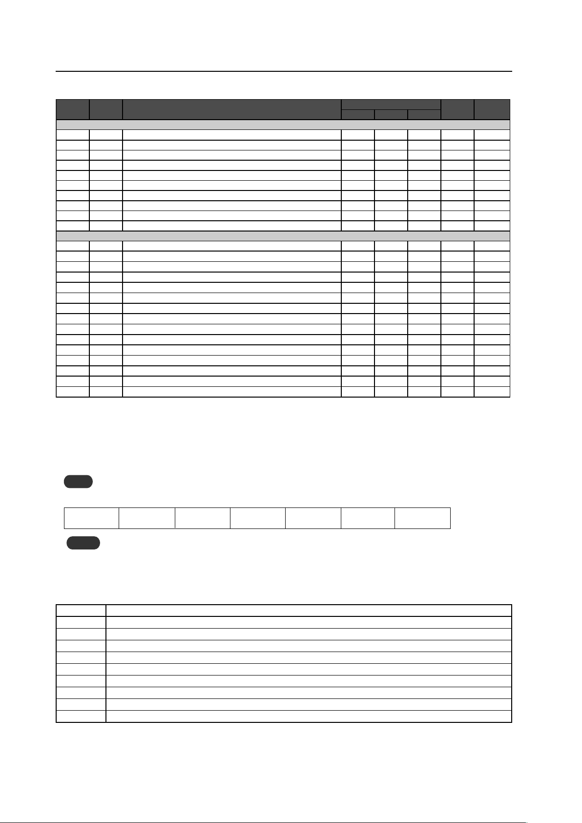
204
RS-232C Adjustment
5.5.6 QUEST Commands
What are QUEST commands?
• Quest commands output TXD such as adjustment data from the panel’s microprocessor to a PC.
• Adjustment and other data is output in ASCII code.
Note
Command names are given inside brackets < >.
• Data output format
Notes
• A QUEST command is invalid when no ID has not been assigned.
• A QUEST command is invalid when a wildcard (*) is used in the ID when sending the command.
STX (02hex)
Command
(3 Byte)
Data ···· Data
ETX (03hex)
Checksum
(2 Byte)
7 Quest Command Table
Command Function
QST Obtains status information.
QPI Obtains integrator/PICTURE information.
QWB Obtains integrator/WHITE BALANCE information.
QPS Obtains integrator/SCREEN information.
QSS Obtains SETUP information.
QSO Obtains Menu Integrator/OPTION information.
QSU Obtains audio status.
QCI Obtains time information.
QAP Obtains various machine names.
7
Other commands
Command
434CMX
Command
425CMX
Function
Number direct Last
memory
Comment
Effective Minimum Maximum
DISPLAY CALL
– DITS01 Displays DISPLAY CALL 1. New
– DITS02 Displays DISPLAY CALL 2. New
– IM0 INFORMATION write-in (1-3 characters).
�
New
– IM1 INFORMATION write-in (4-6 characters).
�
New
– IM2 INFORMATION write-in (7-9 characters).
�
New
– IM3 INFORMATION write-in (10-12 characters).
�
New
– IM4 INFORMATION write-in (13-15 characters).
�
New
– IM5 INFORMATION write-in (16-18 characters).
�
New
– IM6 INFORMATION write-in (19-21 characters).
�
New
– IMD Clears INFORMATION.
�
New
AUXILIARY COMMAND
DW0
+
Subtracts 10 from the adjustment value.
DWF
+
Minimizes the adjustment value.
DWn
+
Subtracts n from the adjustment value. (n=1~9)
UP0
+
Adds 10 to the adjustment value.
UPF
+
Maximizes the adjustment value.
UPn
+
Adds n to the adjustment value (n = 1 to 9).
GST QST Obtains status information.
GPI QPI Obtains integrator/PICTURE information.
GWB QWB Obtains integrator/WHITE BALANCE information.
GPS QPS Obtains integrator/SCREEN information.
GSS QSS Obtains SETUP information.
GSO QSO Obtains Menu Integrator/OPTION information.
– QAP Obtains various machine names. New
– QCI Obtains time information. New
– QSU Obtains audio status. New
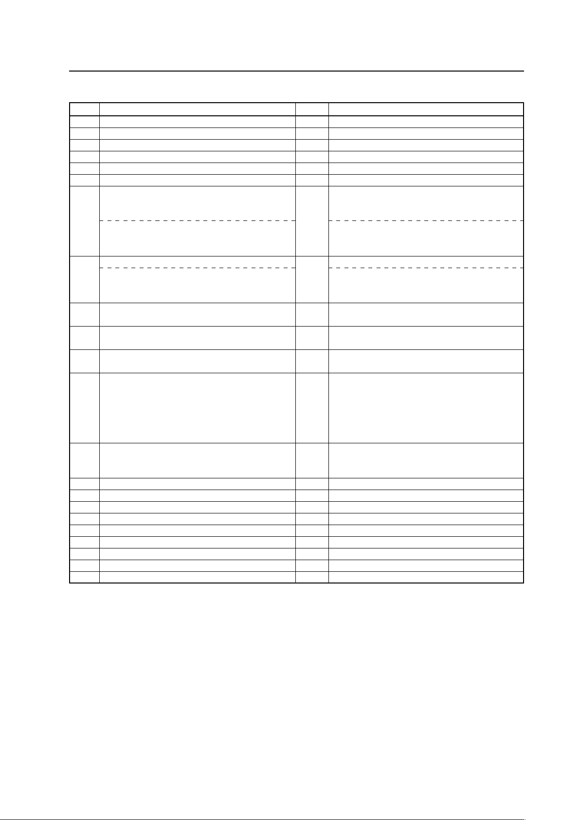
205
RS-232C Adjustment
1) Obtaining QST Status Information
Sequence
Data Content Size Remarks
1 STX 1 Byte 02hex
2 Command echo-back 3 Byte QST (fixed)
3 Generation information 1 Byte 5 (fixed)
4 Inch information 1 Byte 4 (fixed)
5 Forwarding 1 Byte M (fixed)
6 Power source state 1 Byte S: Standby status P: Power supplied status
7 During standby: Standby cause 1 Byte N: Normal standby time
W: Standby time based on POWER MANAGEMENT
S: Standby time based on SD or PD
During power supply: main screen signal status N: normal signal input time
L: no signal input time
O: OUT OF RANGE signal input time
8 During standby or 1 screen display: dummy data 1 Byte
During 2-screen display: sub screen signal status N: normal signal input time
L: no signal input time
O: OUT OF RANGE signal input time
9 Main input function information 3 Byte IN1: INPUT1 IN2: INPUT2 IN3: INPUT3 IN4: INPUT4
IN5: INPUT5
10 Sub input function information 3 Byte IN1: INPUT1 IN2: INPUT2 IN3: INPUT3 IN4: INPUT4
IN5: INPUT5 Note1)
11 Main screen size information 1 Byte 0: DOT BY DOT 1: 4:3 2: FULL 3: ZOOM 5: WIDE 6: 14:9
9: UNDERSCAN A: 2.35:1
12 Two-screen display state 1 Byte 0: OFF (1 screen) 1: SIDE BY SIDE 1
2: PinP (lower right) 3: PinP(upper right)
4: PinP (upper left) 5: PinP(lower left)
6: SIDE BY SIDE 2-L 9: SIDE BY SIDE 2-R
A: SIDE BY SIDE 3 B: SIDE BY SIDE 4-L
C:SIDE BY SIDE 4-R
13 Functional lock information 1 Byte 0: LOCK OFF 1: BUTTONS LOCK 2: IR LOCK
2: IR LOCK 3: IR&BUTTONS LOCK
4: MEMORY LOCK
14 Temperature information 1 (interior) 3 Byte Temperature inside the set (Centigrade) Note 2)
15 Temperature information 2 (SLOT) 3 Byte SLOT temperature (Celsius) Note 2)
16 Temperature information 3 (outside air) 3 Byte Outside air temperature (Celsius) Note 2)
17 Serial No. 15 Byte 15 digit character string
18 Dummy data 3 Byte
19 Dummy data 2 Byte
20 HOUR METER 5 Byte 5 digit number
21 Check sum 2 Byte
22 ETX 1 Byte 03hex
Note 1) During standby and during a single screen display, the unit outputs the value that is in memory.
Note 2) During standby and immediately after POWER ON, the correct value is not output.
In this case, please obtain the information after waiting a short period of time after POWER ON.
These types of information are output as reference information (these are not guaranteed information).
Normally refer to temperature information 3.
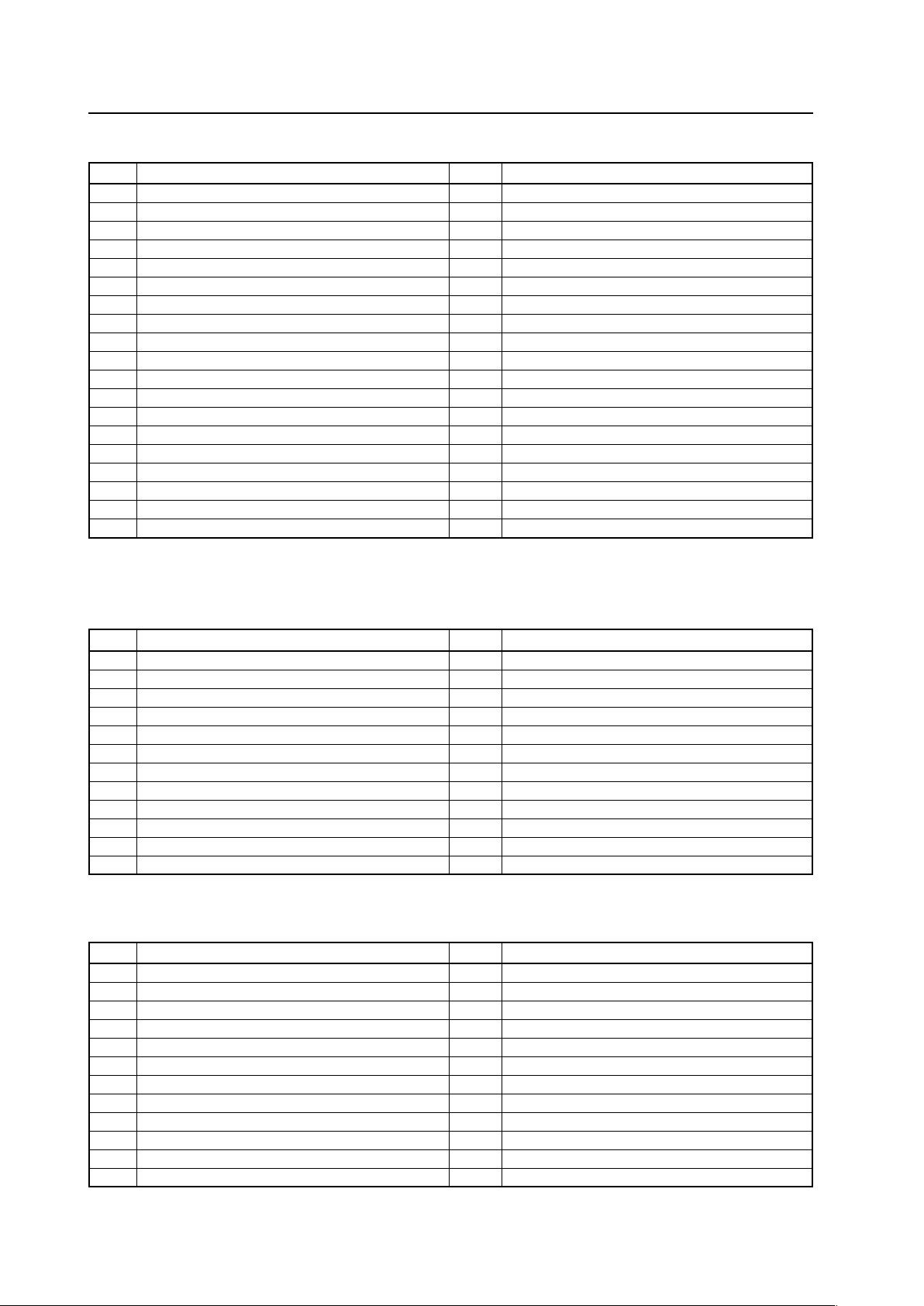
206
RS-232C Adjustment
2) <QPI> Obtaining Integrator/PICTURE information
Sequence
Data Content Size Remarks
1 STX 1 Byte 02hex
2 Command echo-back 3 Byte QPI (fixed)
3 CONTRAST 3 Byte 000 to 255 Note 1)
4 BRIGHTNESS 3 Byte 000 to 255 Note 1)
5 C,DETAIL R (RED) 3 Byte 000 to 060 Note 1)
6 C,DETAIL Y (YELLOW) 3 Byte 000 to 060 Note 1)
7 C,DETAIL G (GREEN) 3 Byte 000 to 060 Note 1)
8 C,DETAIL C (CYAN) 3 Byte 000 to 060 Note 1)
9 C,DETAIL B (BLUE) 3 Byte 000 to 060 Note 1)
10 C,DETAIL M (MAGENTA) 3 Byte 000 to 060 Note 1)
11 H.ENHANCE 3 Byte 000 to 015 Note 1), Note 2)
12 V.ENHANCE 3 Byte 000 to 015 Note 1), Note 2)
13 COLOR 3 Byte 000 to 127 Note 1), Note 3)
14 TINT 3 Byte 000 to 060 Note 1), Note 3)
15 SHARPNESS 3 Byte 000 to 015 Note 1), Note 3)
16 Main input function 3 Byte Same as item 9 of QST commands
17 Main screen size information 1 Byte Same as item 11 of QST commands
21 Check sum 2 Byte
22 ETX 1 Byte 03hex
Note 1) If the signal type is not confirmed, dummy data is output.
Note 2) During video signal input, dummy data is output.
Note 3) During PC signal input, dummy data is output.
3) <QWB> Obtaining integrator/WHITE BALANCE information
Sequence
Data Content Size Remarks
1 STX 1 Byte 02hex
2 Command echo-back 3 Byte QWB (fixed)
3 R.HIGH 3 Byte 000 to 255 Note 1)
4 G.HIGH 3 Byte 000 to 255 Note 1)
5 B.HIGH 3 Byte 000 to 255 Note 1)
6 R.LOW 3 Byte 000 to 255 Note 1)
7 G.LOW 3 Byte 000 to 255 Note 1)
8 B.LOW 3 Byte 000 to 255 Note 1)
9 Main input function 3 Byte Same as item 9 of QST commands
10 Main screen size 1 Byte Same as item 11 of QST commands
11 Check sum 2 Byte
12 ETX 1 Byte 03hex
Note 1) If the signal type is not confirmed, dummy data is output.
4) <QPS> Obtaining integrator/SCREEN information
Sequence
Data Content Size Remarks
1 STX 1 Byte 02hex
2 Command echo-back 3 Byte QPS (fixed)
3 H.POSITION 3 Byte 000 to 255 Note 1)
4 V.POSITION 3 Byte 000 to 255 Note 1)
5 H.SIZE 3 Byte 000 to 064 Note 1)
6 V.SIZE 3 Byte 000 to 064 Note 1)
7 CLOCK 3 Byte 000 to 255 Note 1), Note 2)
8 PHASE 3 Byte 000 to 031 Note 1), Note 2)
9 Main input function 3 Byte Same as item 9 of QST commands
10 Main screen size information 1 Byte Same as item 11 of QST commands
21 Check sum 2 Byte
22 ETX 1 Byte 03hex
Note 1) If the signal type is not confirmed, dummy data is output.
Note 2) During DVI or video input, dummy data is output.
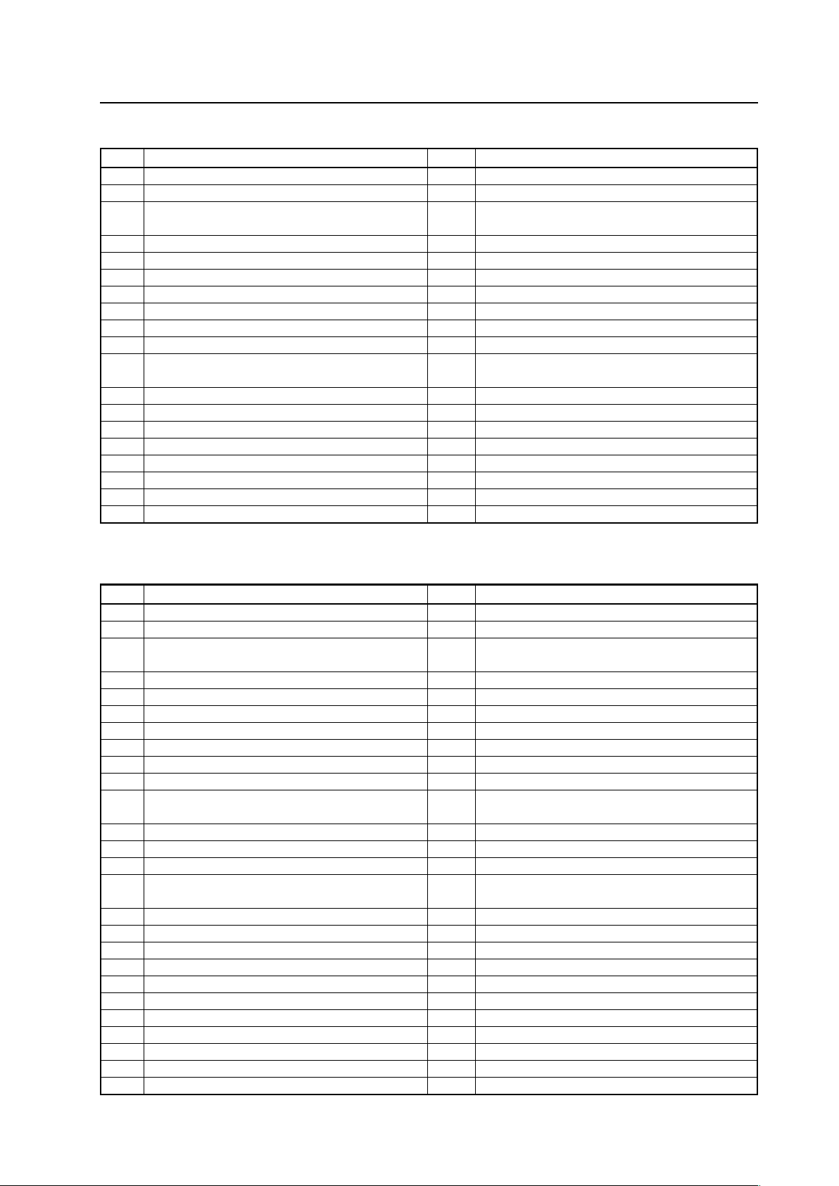
207
RS-232C Adjustment
5) <QSS> Obtaining SETUP information
Sequence
Data Content Size Remarks
1 STX 1 Byte 02hex
2 Command echo-back 3 Byte QSS (fixed)
3 COLOR TEMP. 1 Byte 1: LOW 2: MID LOW 3: MIDDLE 4: MID HIGH
5: HIGH Note 1)
4 POWER MGT. 1 Byte 0: OFF 1: ON
5 AUTO POWER OFF 1 Byte 0: DISABLE 1: ENABLE
6 DNR 1 Byte 0: OFF 1: LOW 2: MIDDLE 3: HIGH Note 1)
7 MPEG NR 1 Byte 0: OFF 1: LOW 2: MIDDLE 3: HIGH Note 1)
8 CTI 1 Byte 0: OFF 1: ON Note 1)
9 PURECINEMA 1 Byte 0: OFF 1: ON Note 1)
10 COLOR DECODING 1 Byte 1: RGB 2: COMP1 3: COMP2 Note 1)
11 COLOR SYSTEM 1 Byte 1: AUTO 2: NTSC 3: PAL 4: SECAM 5: 4.43NTSC
6: PAL M 7: PAL N Note 1)
12 DVI SET UP (PLUG/PLAY) 1 Byte 1: PC 2: VIDEO Note 1)
13 DVI SET UP (BLACK LEVEL) 1 Byte 1: LOW 2: HIGH Note 1)
14 BRT.ENHANCE 1 Byte 0: OFF 1: ON Note 1)
15 SUB VOLUME 2 Byte 00 to 20
16 Main input function 3 Byte Same as item 9 of QST commands
17 Main screen size information 1 Byte Same as item 11 of QST commands
18 Check sum 2 Byte
19 ETX 1 Byte 03hex
Note 1) In the case of set data that cannot be output because of the type of input signal, dummy data is output.
6) <QSO> Obtaining menu integrator/OPTION information
Sequence
Data Content Size Remarks
1 STX 1 Byte 02hex
2 Command echo-back 3 Byte QSO (fixed)
3 ENERGY SAVE 1 Byte 1: STANDARD 2: MODE1 3: MODE2 4: MODE3
5: AUTO
4 Program timer 1 Byte 0: OFF 1: ON
5 SCREEN MANAGEMENT (ORBITER) 1Byte 0: OFF 1: MODE1 2: MODE2 3: MODE3
6 SCREEN MANAGEMENT (SOFT FOCUS) 1 Byte 0: OFF 1: 1 2: 2 3: 3 4: 4
7 AUTO SETUP MODE 1 Byte 0: INACTIVE 1: ACTIVE
8 AUTO FUNCTION 1 Byte 0: OFF 1: INPUT1 2: INPUT4
9 PIP DETECT 1 Byte 0: INACTIVE 1: ACTIVE
10 SPLIT FREEZE 1 Byte 0: OFF 1: SIDE BY SIDE 2: PIP
11 SCREEN MASK 1 Byte 0: OFF 2: INVERSE 3: WHITE 4: RED 5: GREEN 6: BLUE
7: YELLOW
12 SIDE MASK R-LEVEL 3 Byte 000 to 255
13 SIDE MASK G-LEVEL 3 Byte 000 to 255
14 SIDE MASK B-LEVEL 3 Byte 000 to 255
15 VIDEO WALL (MODE) 1 Byte 0: OFF 1: 1 screen 2: 4 screens 3: 9 screens 4: 16 screens
5: 25 screens
16 VIDEO WALL (POSITION) 2 Byte 01 to 56
17 VIDEO WALL (TYPE) 1 Byte 0: NORMAL 1: ADJUSTED
18 VIDEO WALL (POWER ON DELAY) 1 Byte 0: OFF 1: ON 2: MODE1 3: MODE2
19 VIDEO WALL (PLE LINK) 1 Byte 0: OFF 1: ON
20 VIDEO WALL (REPEAT TIMER) 1 Byte 0: OFF 1: ON
21 FAN CONTROL 1 Byte 1: AUTO 2: MAX
22 OSD 1 Byte 0: OFF 1: ON
23 OSD SIZE 1 Byte 0: LARGE 1: SMALL
24 OSD ANGLE 1 Byte 0: H 1: V
25 FRONT INDICATOR 1 Byte 0: OFF 1: ON
26 COLOR MODE 1 Byte 1: NORMAL 2: STUDIO
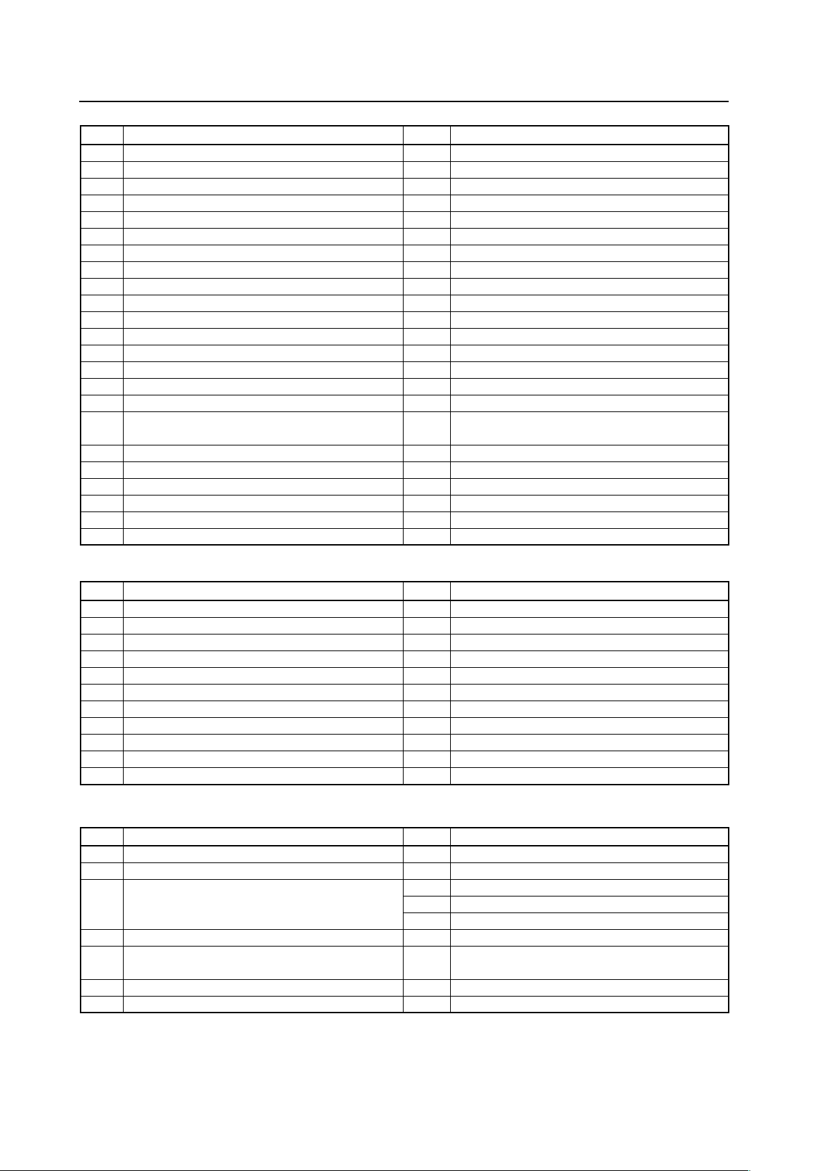
208
RS-232C Adjustment
Sequence
Data Content Size Remarks
27 PRO USE UNDERSCAN 1 Byte 0: OFF 1: ON
28 PRO USE IMAGE PROCESS 1 Byte 1: NORMAL 2: PURE 3: MONOTONE 4: HIGH CONTRAST
29 PRO USE SYGNAL TYPE 1 Byte 1: MOTION 2: STILL 3: NONE STD
30 FRC 1 Byte 0: OFF 1: ON
31 POWER ON MODE INPUT 1 Byte See the figure below.
32 POWER ON MODE MULTI MODE 1 Byte See the figure below.
33 POWER ON MODE MULTI INPUT 1 1 Byte 1: INPUT 2: INPUT2 3: INPUT3 4: INPUT4 5: INPUT5
34 POWER ON MODE MULTI INPUT 2 1 Byte 1: INPUT 2: INPUT2 3: INPUT3 4: INPUT4 5: INPUT5
35 POWER ON MODE VOLUME 2 Byte 0 to 42: In the case of lost memory, FF
36 SEAMLESS SW 1 Byte 0: OFF 1: ON
37 SEAMLESS SW SELECT1 1: INPUT 2: INPUT2 3: INPUT3 4: INPUT4 5: INPUT5
38 SEAMLESS SW SELECT2 1 Byte 1: INPUT 2: INPUT2 3: INPUT3 4: INPUT4 5: INPUT5
39 MIRROR MODE 1 Byte 0: OFF 1: X 2: Y 3: XY
40 MULTI SCREEN SET (S BY S SIZE) 1 Byte 1: NORMAL 2: FULL
41 MULTI SCREEN SET (S BY S LAYOUT) 1 Byte 1: MODE1 2: MODE2 3: MODE3
42 MULTI SCREEN SET (PIP SIZE) 1 Byte 1: 1 (SMALL) to 4: 4 (LARGE)
43 MULTI SCREEN SET (TRANSLUCENT) 1 Byte 0: OFF 1: 10 % 2: 20 % 3: 30 % 4: 40 % 5: 50 %
6: 60 % 7: 70 % 8: 80 %
44 MULTI SCREEN SET (BANNER PIP) 1 Byte 0: OFF 1: TOP 2: MID HIGH 3: MID LOW 4: BOTTOM
45 MULTI SCREEN SET (BANNER INPUT) 1 Byte 1: INPUT1 2: INPUT2
46 Main input function 3 Byte Same as item 9 of QST commands
47 Main screen size information 1 Byte Same as item 11 of QST commands
48 Check sum 2 Byte
49 ETX 1 Byte 03hex
7) <QSU> obtaining the audio status
Sequence
Data Content Size Remarks
1 STX 1 Byte 02hex
2 Command echo-back 3 Byte QSU (fixed)
3 Main volume 3 Byte 000 to 042
4 Audio mute status 1 Byte 0: OFF 1: ON
5 INPUT1 sub volume 3 Byte 000 to 020
6 INPUT2 sub volume 3 Byte 000 to 020
7 INPUT3 sub volume 3 Byte 000 to 020
8 INPUT4 sub volume 3 Byte 000 to 020
9 INPUT5 sub volume 3 Byte 000 to 020
10 Check sum 2 Byte
11 ETX 1 Byte 03hex
8) <QCI> Obtaining time information
Sequence
Data Content Size Remarks
1 STX 1 Byte 02hex
2 Command echo-back 3 Byte QCI (fixed)
3 Time information 2 Byte Hour (24 hour system) 00 to 23 Note 1)
2 Byte Minute 00 to 59 Note 1)
2 Byte Second 00 to 59 Note 1)
4 Dummy data 8 Byte
5 Day of week 1 Byte 1: Sunday 2: Monday 3: Tuesday 4: Wednesday
5: Thursday 6: Friday 7: Saturday Note 1)
6 Check sum 2 Byte
7 ETX 1 Byte 03hex
Note 1) During standby and when this command was initially set, the value at the time that power was finally shut off is transmitted.
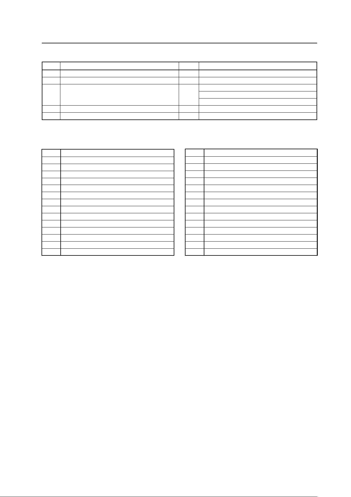
209
RS-232C Adjustment
9) <QAP> Obtaining machine name
Sequence
Data Content Size Remarks
1 STX 1 Byte 02hex
2 Command echo-back 3 Byte QAP (fixed)
3 Machine name information 18 Byte A/J (North America/domestic model): PDP-425CMX/LUC5***
G (Europe-general model): PDP-42MXE10/LDFK5*
CKD (European CKD model): PDP42MXE10/YVXK5*
4 Check sum 2 Byte
5 ETX 1 Byte 03hex
7 Table of commands not compatible with PDP-434CMX to PDP-425CMX
AJN Ends 232C integrator adjustment mode.
AJY Starts 232C integrator adjustment mode.
COF Displays present color off setting.
COFS00 Does not set color off.
COFS01 Sets color off.
DPR Resets still picture movement function.
FXO Selects audio output fix.
FRCS02 Sets FRC to MODE3.
FRCS03 Sets FRC to MODE3.
GRAS04 Sets gradation to “DRE MID”.
GRAS05 Sets gradation to “DRE HIGH”.
GRAS06 Sets gradation to “DRE LOW”.
GRAS07 Sets gradation to “HIGH CONTRAST”.
LNN Prohibits loudness.
LNY Permits loudness
MCN Turns off MASK CONTROL.
MCY Turns on MASK CONTROL.
MGFS01 Turns on VIDEO WALL.
MSCS01 Turns on MULTI SCREEN.
SIM Displays present setting of SIDE MASK.
SIMS01 Sets setting of SIDE MASK to normal.
SIMS02 Sets setting of SIDE MASK to overlay 1.
SIMS03 Sets setting of SIDE MASK to overlay 2.
SZMS04 Sets screen size to CINEMA.
SZMS08 Sets screen size to FULL 1035i.
MIR Displays present MIRROR MODE setting
PLN Turns off center brightness correction.
PLY Turns on center brightness correction.
PUCS02 Sets PURE CINEMA to advance.
VRO Selects audio output variable.
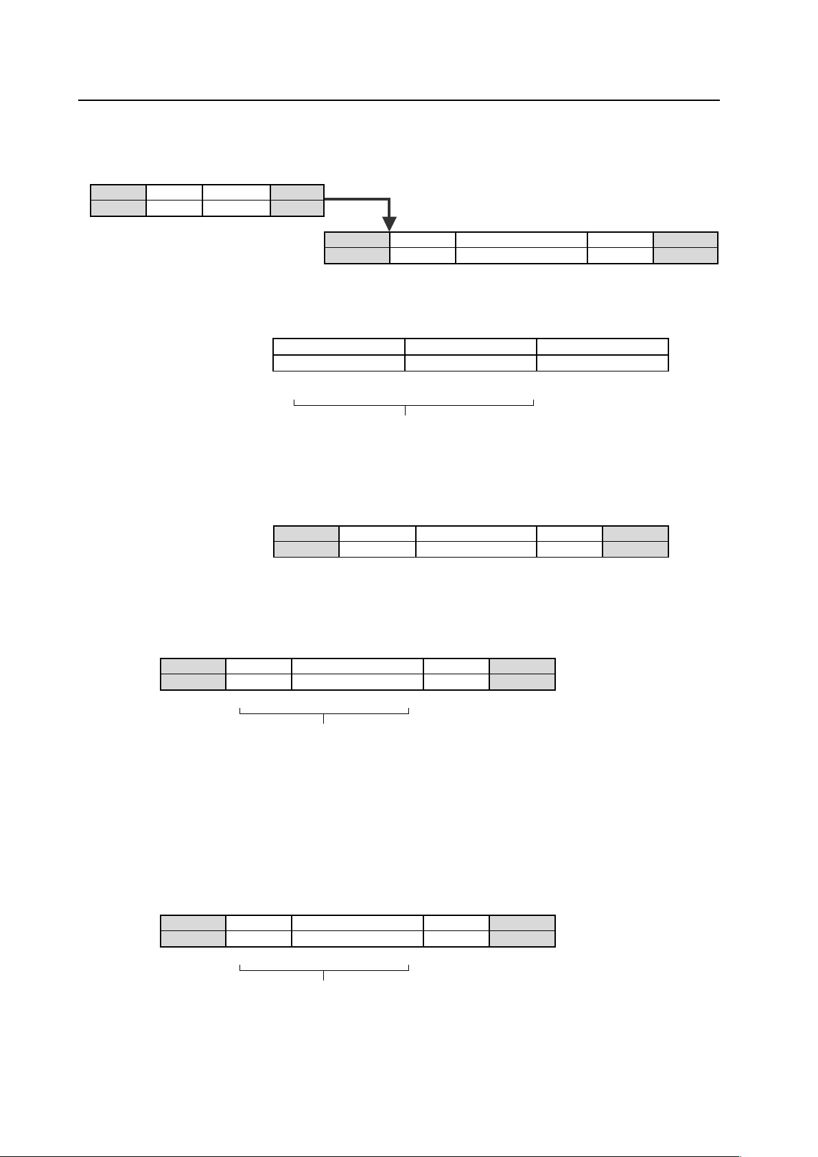
210
RS-232C Adjustment
7 Check Sum
This is data to which 2-Byte ASCII code is added to a data group returned by a QUEST command.
STX
02 (hex) 2 Byte 3 Byte 03 (hex)
ID
QUEST command
ETX
STX
02 (hex)
QUEST command
3 Byte
Data
*Byte
Check sum
2 Byte
ETX
03 (hex)
PC side
Set side
A detailed example is given below.
Example) The check sum value that is added when the QUEST command “QAA” returned the following 6-Byte data string.
QUEST command
QAA
Data (6 Byte)
100128
Data
100128
Check sum
0B
ETX
03 (hex)
Check sum
xx (before calculation)
Data group (ASCII)
+ check sum
47 41 41 31 30 30 31 32 38
When these values are added the result is 1F5 (hex).
As the data format, OB is converted to ASCII code and sent.
The following data is output from the Plasma Display side.
xx, where xx is 0B (hex), is added to 1F5 so the last two digits are 00 (in this case 200).
≠
≠
≠
≠
STX
02 (hex)
QUEST command
QAA
The data group is put into binary code one
character at a time then displayed (only the
last two digits are displayed).
7 Examples of check sum applications
Example 1) When the data is missing 1 Byte
47 41 31 30 30 32 38
Here, the check sum [OB (hex)] and the calculated [3C (hex)] do not match.
Data
100 (missing data) 28
Check sum
0B
ETX
03 (hex)
STX
02 (hex)
QUEST command
QAA
The data group is calculated according to rules by a PC application,
and when these values are added the result is 1C4 (hex).
≠
≠
≠
A value xx, where xx is 3C (hex), is added to 1C4 such that the last
two digits are 00 (in this case 200).
Since they do not match, the PC application sends the QUEST command
again and gets the data again.
Example 2) When 1 Byte of data in the data is unreadable
47 41 31 30 33 30 32 38
Here, the check sum [OB (hex)] and the calculated [09 (hex)] do not match.
Data
100328
Check sum
0B
ETX
03 (hex)
STX
02 (hex)
QUEST command
QAA
The data group is calculated according to rules by a PC application,
and when these values are added the result is 1F7 (hex).
≠
≠
≠
A value xx, where xx is 09 (hex), is added to 1F7 such that the last
two digits are 00 (in this case 200).
Since they do not match, the PC application sends the QUEST command
again and gets the data again.
* The returned data group is in capital letters. Please keep this in mind when introducing it into the binary
display.

211
Screen Burning
5.6 Screen Burning
When the same image is reproduced for a long period (still image, telop, etc.), the image is burned into to screen. It may
be difficult to remove this image. Burning should be managed by making necessary changes in the video software,
projection method, system configuration etc.
This display has a function that reduces this kind of burning.
7 Menu mode
1 ENERGY SAVE setting (Refer to section 5.3.4, “Adjustment and setting in the Menu Mode 4) Energy Saving
Setting” (pg. 119) and 5.3.7, “Adjustment and setting in the Menu Mode 12) Energy Saving Setting” (pg. 143).)
The screen brightness is controlled according to the input signal and by the brightness of the room.
2 ORBITER Setting (Refer to section 5.3.4, “Adjustment and setting in the Menu Mode 5) Orbiter Setting” (pg. 121)
and 5.3.7, “Adjustment and setting in the Menu Mode 13) Orbiter Setting” (pg. 145).)
This function gradually and randomly moves the image position vertically and/or horizontally after a set amount of
time. Or the edges of the images are restricted by setting soft focus in order to soften images edges.
7 Integrator Mode
1 SCREEN MASK Setting (Refer to section 5.4.3, “Adjustment and setting in the Integrator Mode 9) SCREEN
MASK Setting” (pg. 164).)
An inverse or full mask signal appears on the screen.
When a full mask is prepared beforehand, it becomes more difficult for the screen to become burned.
Using an inverse signal may be an emergency measure when the screen is burned from displaying a still image.
However, completely removing the burn is not possible.
2 SIDE MASK Setting (Refer to section 5.4.3, “Adjustment and setting in the Integrator Mode 10) SIDE MASK
Setting” (pg. 165).)
This setting adjusts the method of displaying the SIDE MASK signal and adjusts the signal level of the SIDE
MASK signal.
7 Menu Mode and Integrator Mode
1 PROGRAM TIMER Setting (Refer to section 5.3.4, “Adjustment and setting in the Menu Mode 11) Program Timer
Setting” (pg. 127) and 5.3.7, “Adjustment and setting in the Menu Mode 19) Program Timer Setting” (pg. 151),
”5.4.3, “Adjustment and setting in the Integrator Mode 8) Program Timer Setting” (pg. 163).)
The display contents change at a predetermined time according to set conditions.
7 Standard Functions (Settings cannot be changed)
1 Auto Brightness Adjustment (still image detection)
When an image that has little or no motion, such as a photograph or computer screen, is displayed for a long
period, the screen may appear dimmer. This feature is part of the screen-protection function, to automatically
adjust the brightness and protect the screen when an image with little or no motion is detected. This function
activates after an image with little or no motion has been detected for 3 minutes.
Note
This function is not found in the menu (the setting cannot be changed).
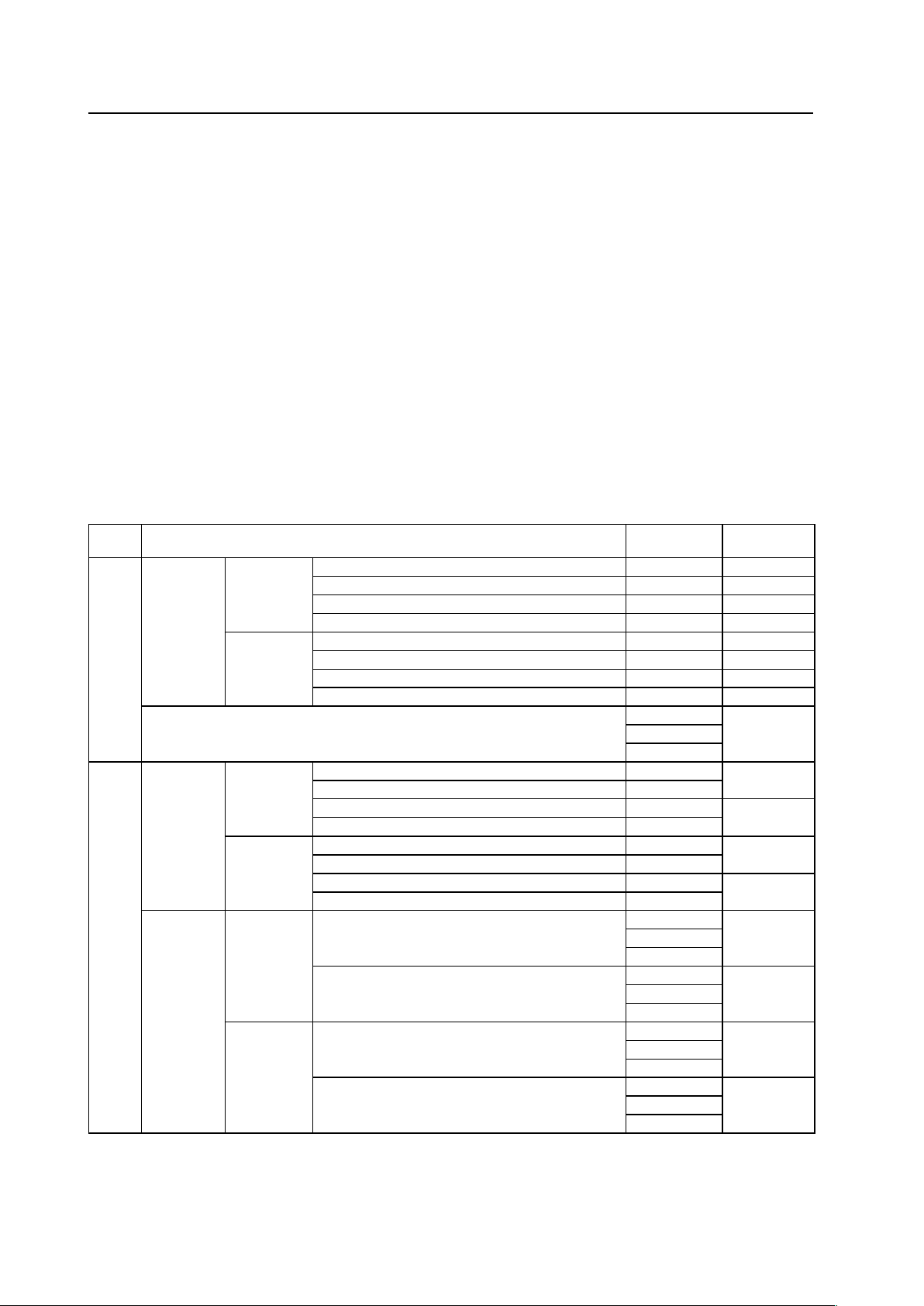
212
5.7 Precautions on Connecting Camera Images
Connecting and using moving images that are nearly still, such as images from a surveillance camera, could damage
the panel and reduce the life or be the cause of other issues.
In this situation, it is necessary to set the image quality beforehand.
For instructions on setting the image quality, contact your Pioneer representative.
(Set the ‘ENERGY SAVE’ function to ‘MODE2’ or ‘MODE3’.)
This setting is not required when just showing a still image from a PC or digital camera.
5.8 Concerning frame delay (lip sync)
The following table shows the approximate time after the video signal is input until it appears on the display.
It is the guideline when considering the audio delay time following the video (lip sync).
The video signal is, in multi-screen mode, delayed by approximately 1 V (there is no delay that exceeds 4 V) in the following
cases.
• Right screen of side by side mode (left screen in a case where the same signals are combined)
• Subscreen of picture in picture mode
There is no frame delay with other causes.
(These data are reference values; they cannot be ensured.)
Precautions on Connecting Camera Images/Concerning frame delay (lip sync)
FRC
setting
Video input signal
Input vertical
frequency (Hz)
Frame delay
number (V)
ON
Video signal
Normal time
PAL, SECAM, PAL N, 625i (576i), 1125i (1080i) 50 4
NTSC, 4.43NTSC, PAL M, 525i (480i), 1125i (1080i) 60 3
625p (576p), 750p (720p),1125p (1080p) 50 2
525p (480p), 750p (720p), 1125p (1080p) 60 1
When zoom
function is
used
*2
PAL, SECAM, PAL N, 625i (576i), 1125i (1080i) 50 4
NTSC, 4.43NTSC, PAL M, 525i (480i), 1125i (1080i) 60 4
625p (576p), 750p (720p), 1125p (1080p) 50 2
525p (480p), 750p (720p), 1125p (1080p) 60 2
PC signal
60
2
75
85
OFF
Video signal
Normal time
PAL, SECAM, PAL N, 625i (576i), 1125i (1080i) 50
3
NTSC, 4.43NTSC, PAL M, 525i (480i), 1125i (1080i) 60
625p (576p), 750p (720p), 1125p (1080p) 50
1
525p (480p), 750p (720p), 1125p (1080p) 60
When zoom
function is
used
*2
PAL, SECAM, PAL N, 625i (576i), 1125i (1080i) 50
4
NTSC, 4.43NTSC, PAL M, 525i (480i), 1125i (1080i) 60
625p (576p), 750p (720p), 1125p (1080p) 50
2
525p (480p), 750p (720p), 1125p (1080p) 60
PC signal
Normal time
FRC setting object signal
*1
50
1
60
72
FRC setting non-object signal
60
2
75
85
When zoom
function is
used
*2
FRC setting object signal
*1
50
2
60
72
FRC setting non-object signal
60
2
75
85
*1: The FRC object signal in the PC signal is as follows.
640x480@60 Hz VGA, 848x480@60 Hz WVGA, 1280x768@60 Hz WXGA 1024x768@60 Hz XGA, 1280x1024@60 Hz SXGA,
1024x768@50 Hz XGA 1024x768@72 Hz XGA, 640x480@50 Hz VGA (only analog input), 848x480@50 Hz WVGA 1280x768@50 Hz
WXGA, 1280x768@72 Hz WXGA, 1400X1050@60 Hz SXGA+
*2: The zoom function indicates the expansion functions based on H size, V size, and video wall in point zoom and integrator modes.
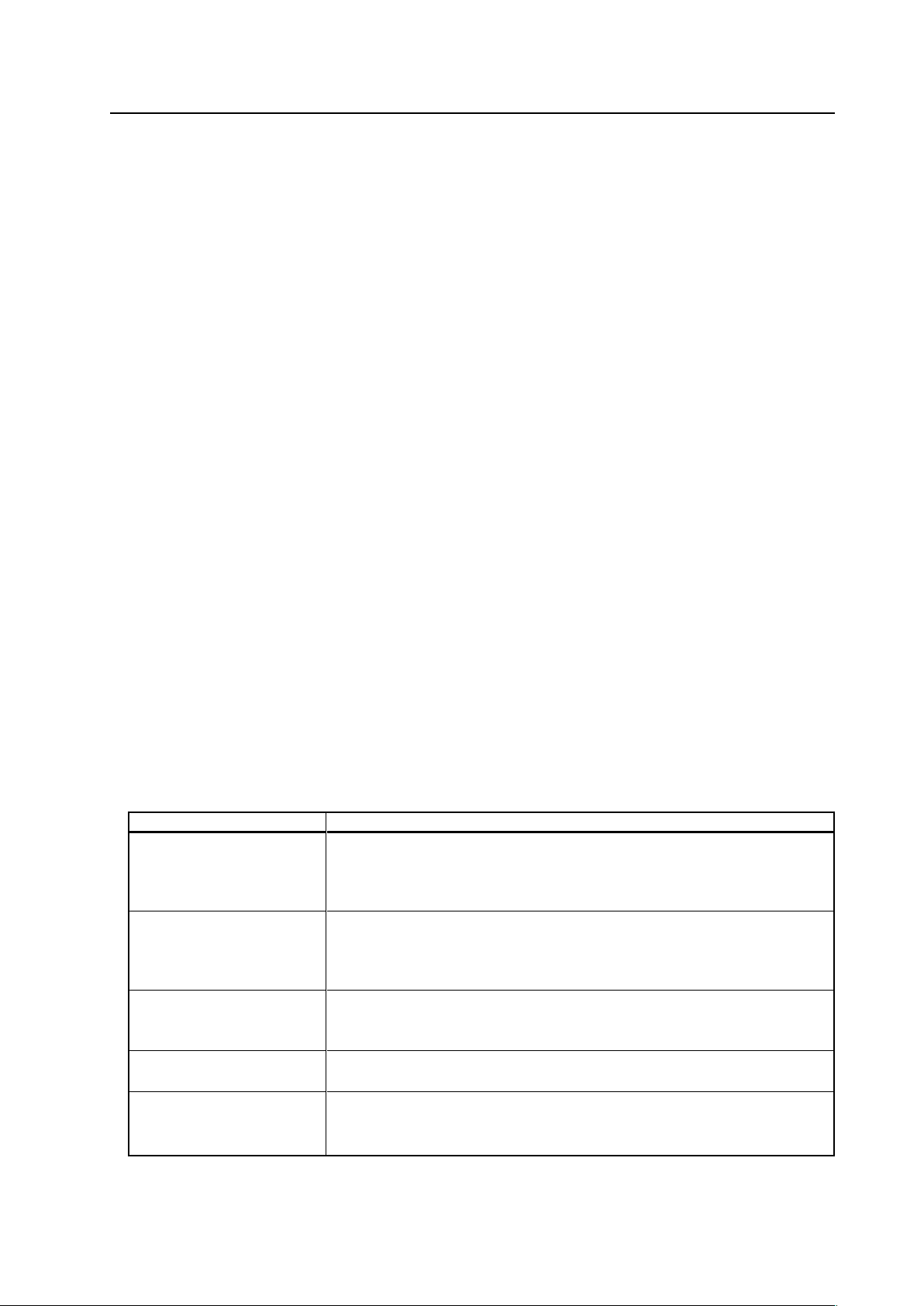
213
6.1 Precautions
1) If the power shuts down and stays OFF for a long period, an internal problem has probably occurred (failing part,
etc.).
Turn OFF the main power switch on the Plasma Display then wait 1 to 2 minutes and try turning the power ON again.
If the power goes OFF again, the display need to be serviced.
If the display operates normally, the power reset has cleared the issue.
2) When an image (still image, telop, etc.) is shown on the screen for a long period, there is a possibility that the image
could be burned in. This should be managed by making necessary changes in the imaging software, display method,
system configuration etc.
3) The following kinds of input signals could cause inferior image quality (When a PDA-5003/PDA-5004 is used).
• Video signal that has been dubbed (copied) repeatedly
• Copyright-protected signals
• Scrambled cable TV signals
• Signals with a sync signal and video signal that are extremely out of phase
4) The fan starts operating when the surrounding temperature is greater than 32 °C (the fan rpm becomes faster as the
temperature increases, this is normal).
5) Screen-saver function (still image detection)
When an image having little motion such as a photograph or PC screen is displayed continuously, the may appear
dimmer. To protect the plasma panel, the screen-saver function detects images with little or no motion and
automatically adjusts the brightness. This action is not an indication that the display is failing.
Time until the screen-saver function operates:
• Normal-operation mode/menu mode: Approximate 3 minutes after the power is turned ON or after the input is
switched.
7 Self-diagnosis Function
When there is an operating or connection error, a message appears on the screen.
After reading the contents of the error message, check the condition of the unit.
Precautions
Error Message
CAUTION
OUT OF RANGE
UNSUPPORTED SIGNAL
SIGNAL NG
WARNING
THERMAL ALERT
SHUT DOWN
WARNING
FAN FAILURE
SHUT DOWN
ERROR
INVALID KEY ENTRY
SHUT DOWN
Remedy
¶ The current signal input is not supported by the unit. Check the table of supported
input signals on pages 94 - 97 and change the output signal setting.
¶ Turn OFF the main power.
¶ Check whether the surrounding temperature is high.
¶ If the cooling vents on the display are blocked, remove the obstacles blocking the
vents.
¶ There is a problem with the fan. Immediately turn OFF the power and contact the
Pioneer service center or dealer.
¶ An invalid operation was attempted. Check the input signals, connections and
settings.
¶ Turn the main power OFF, wait 1 or 2 minutes and turn the power ON again. If the
problem still persists, remove the power plug from the outlet and contact a Pioneer
service center or dealer.

214
Maintenance
Name Part Number
Cleaning cloth: Wiping cloth AED1285
Cleaning cloth: Minimax GED-009
Cleaning liquid: B4 GEM1004
1) Be sure to unplug the power cord from the power outlet before performing maintenance.
2) Cabinet and Remote-control Unit
Never use solvents such as benzene or thinner. Using such solvents could cause the cabinet and remote control to
degrade and could cause the coating to peel.
Wipe the cabinet and remote control with a soft cloth. If there is heavy soiling, soak a soft cloth in water mixed with
a mild detergent. Ring out the water well then clean the panel. Dry the chassis by wiping with a soft, dry cloth.
3) Screen (front protection panel)
The screen (front protection panel) is treated with a special coating to prevent glare and is very delicate. To clean it,
remove any dust and then wipe it gently with a soft cloth. Do not clean it with tissue or a rough, textured cloth.
DO NOT use solvents such as benzene or thinner to clean the as this could damage or discolor the display panel.
The following cleaning cloths and cleaning liquid are recommended.
In the case of light soiling, remove the dust and then gently wipe with a Minimax cloth. If there is heavy soiling,
remove the dust then apply a small amount of B4 cleaning liquid to an area of the Minimax cloth. Clean the panel. If
any of the cleaning chemical left on the unit may make the surface uneven. After the B4 has dried, wipe it clean with
a dry Minimax cloth.
4) Vents
Dust should be removed from the cooling vents on the sides and rear of the unit and in the fan installation area once
a month with a vacuum cleaner set on LOW. Also, be sure that the main power switch has been turned OFF before
cleaning the vents. Using the unit with accumulated dust causes the internal temperature to rise and could cause fire
or other trouble to occur.
5) Readjustment of the White Balance
This unit uses phosphor elements as in a CRT display, and they degrade over time, reducing the brightness. Since,
blue phosphor elements degrade faster than red and green.
* Occasional readjustment of the white balance may be beneficial.