Loading ...
Loading ...
Loading ...
20
Router Table Assembly
ALWAYS MAKE SURE THAT
THE ROUTER IS TURNED OFF AND THE POWER
CORD IS UNPLUGGED BEFORE MAKING
ANY ADJUSTMENTS.
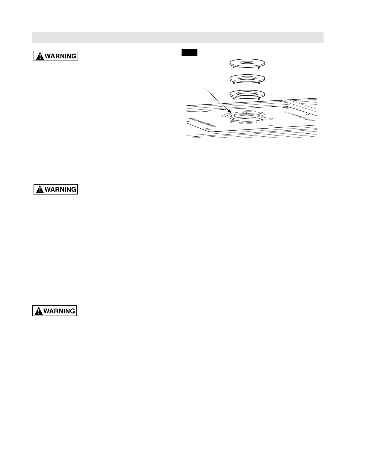
TABLETOP INSERTS (Fig. 16)
This router table includes three tabletop inserts with the
following hole sizes:
• 1″ in diameter (3), for use with bits with diameters
up to 7/8″
• 2″ in diameter (4), for use with bits with diameters
up to 1
7
⁄8″
• 2
3
⁄4″ in diameter (5), for use with bits with diameters
up to 2
5
⁄8″
No insert is used for bits with diameters over 2
5
⁄8″ and
up to 3
1
⁄2″.
Do NOT use the router table with
bits over 3
1
⁄2″ in diameter!
TO INSTALL TABLETOP INSERTS (Fig. 16):
1.Select the tabletop insert that best accommodates
the router bit to be used.
2.Press the insert into the large hole in the router
mounting plate (Fig. 16). If the fence is in the way,
loosen the clamping knobs on the fence support
brackets and slide the fence back out of the way.
3.Press down evenly over the tabs until the insert locks
into place.
4.To remove, pull up gently until the tabs disengage.
When not in use, store tabletop inserts behind the
storage panel in the table leg or in another
convenient place.
DO NOT attempt to remove
tabletop inserts from the tabletop unless the
router is unplugged.
1″ HOLE (3)
2″ HOLE (4)
2
3
⁄4″ HOLE (5)
3
5
⁄8″ HOLE
IN ROUTER
MOUNTING
PLATE
FIG. 16
Loading ...
Loading ...
Loading ...