Loading ...
Loading ...
Loading ...
Router Table Assembly
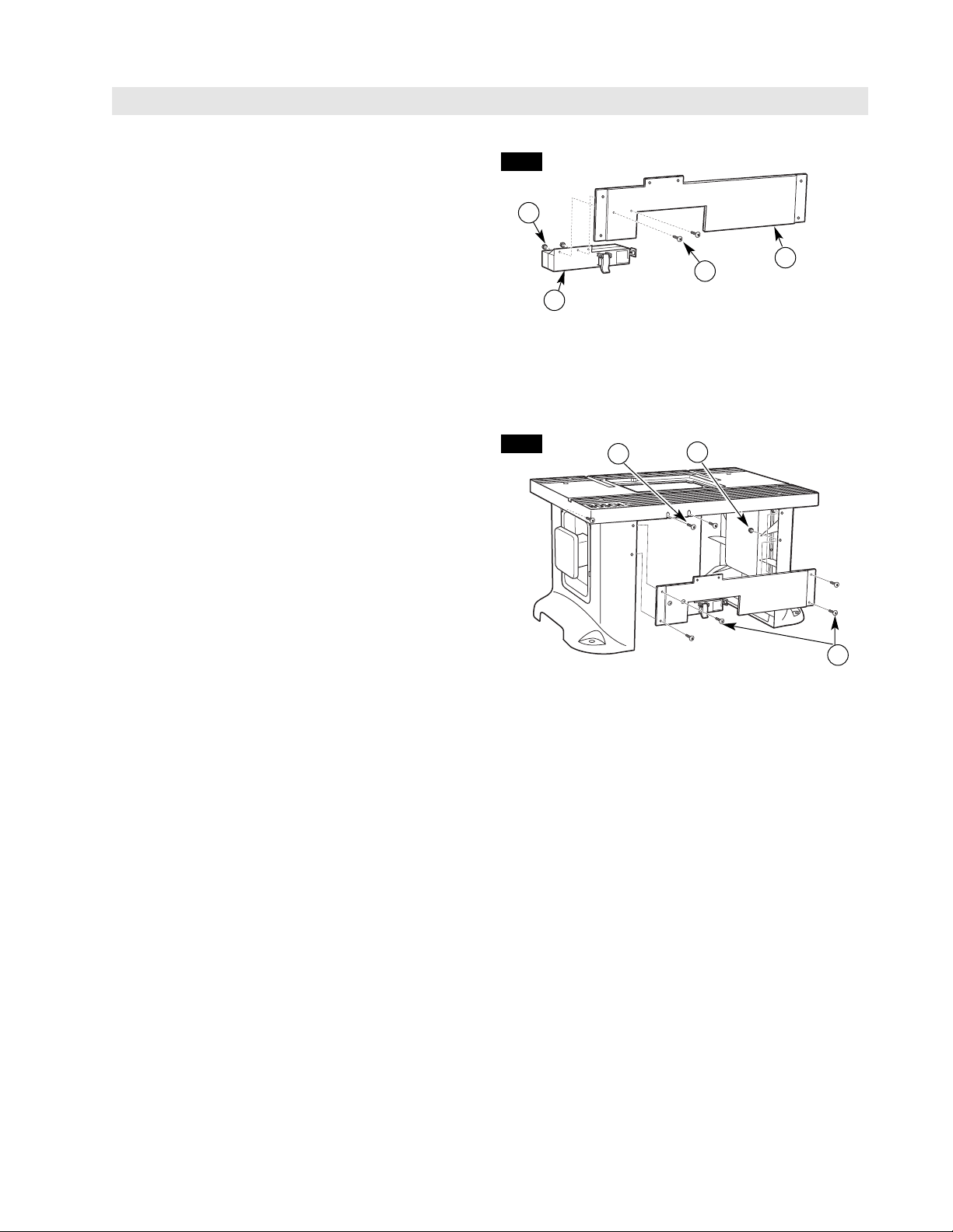
ATTACH THE SWITCH/FASCIA ASSEMBLY
TO THE ROUTER TABLE (FIG. 4)
NOTE: The fascia assembles to the inside of both
the table legs and the router tabletop.
1.Line up the holes on the fascia panel with the holes
in the table legs and the two slots on the front of the
router tabletop.
2. Attach the fascia panel to the router table top using
two #10-32 x 3/4″ truss-head machine screws (30)
and two #10-32 KEPS nuts (24), as shown in Fig. 4.
3.Attach the fascia to the legs using four #10-32 x 3/4″
truss-head machine screws (30) and four #10-32
KEPS nuts (24), as shown in Fig. 4.
4.TIGHTEN all screws SECURELY.
FIG. 4
11
ATTACH THE SWITCH TO THE FASCIA
(FIG. 3)
1.Align the two outermost holes on the top of the switch
assembly (10) with the holes in the front fascia panel
(9), as shown in Fig. 3.
2.Insert two #10-32 KEPS nuts (24) into the
hex-shaped recesses in the back of the switch
assembly (10), toothed side out, and secure the
switch to the fascia panel with two #10-32 x 3/4″
truss-head machine screws (30) while holding the
KEPS nuts in place in the recess with your finger.
FIG. 3
24
30
10
9
24
30
30
Loading ...
Loading ...
Loading ...