Loading ...
Loading ...
Loading ...
English
19
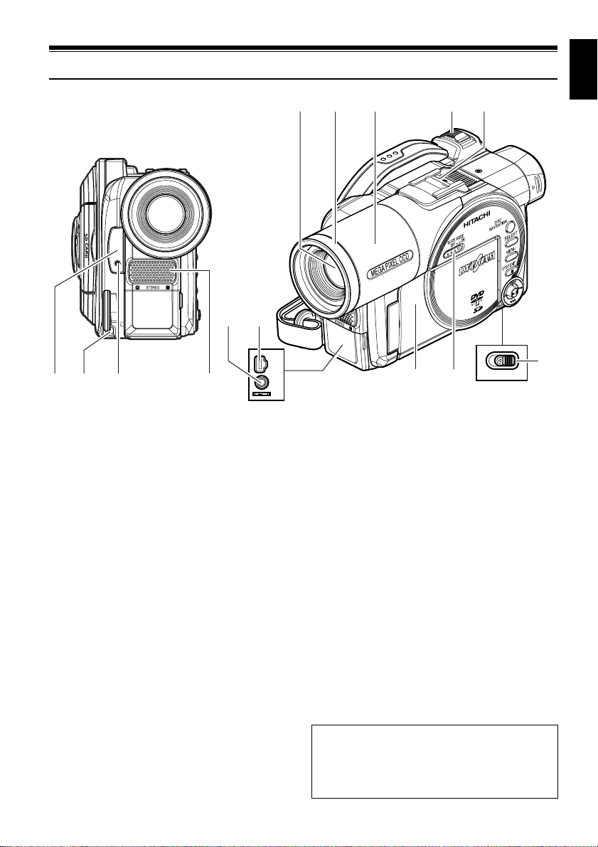
Names of Parts
1 Infrared receiver (P. 37)
When the remote control is used to operate the
DVD video camera/recorder, this receiver will
receive the infrared signal.
2 Lens cap string attachment hole (P. 35)
3 Recording indicator (P. 106)
The red indicator will light during recording.
4 Stereo microphone (P. 80)
5 Optical 18× zoom lens (DZ-MV550E)
Optical 10x zoom lens (DZ-MV580E)
(P. 60)
6 Lens hood (P. 61)
Always remove this lens hood when using
generally available tele-conversion or wide-
conversion lens.
7 Lens cover (P. 37)
You can replace the lens cover with either of the
two covers provided.
8 Zoom lever (P. 60)
Push the lever to the T side for telephoto, or to
the W side for wide-angle.
9 Accessory shoe
Only for DZ-MV580E:
The optional video flash, etc. can be attached
here. (See the instruction manual of device to be
attached for details.)
10 External microphone jack (P. 80)
11 AV input/output jack (P. 81, 87)
AV output jack on DZ-MV550E (UK) and DZ-
MV580E (UK).
12 2.5" type liquid crystal display (inside)
(P. 39)
13 QUICK MODE switch (P. 67)
To switch the menu display on screen between
Normal mode and Quick mode.
14 BATTERY EJECT switch (P. 44)
The BATTERY EJECT switch is located on the
bottom of this DVD video camera/recorder:
Slide it when removing the battery.
A/V
MIC
BATTERY EJECT
14
12 13
56 89
(Inside the cover)
(Bottom)
10 11
123 4
7
Although the external appearances of DZ-
MV550E and DZ-MV580E are different, the
method of operating both models is identical.
DZ-MV580E illustrations are used in this
manual.
Loading ...
Loading ...
Loading ...