24
VAC
AKL08RF Wireless Valve Relay Control
Installation and Wiring Guide
For PDF Installation guide go to www.salusinc.com
Boiler
Connection
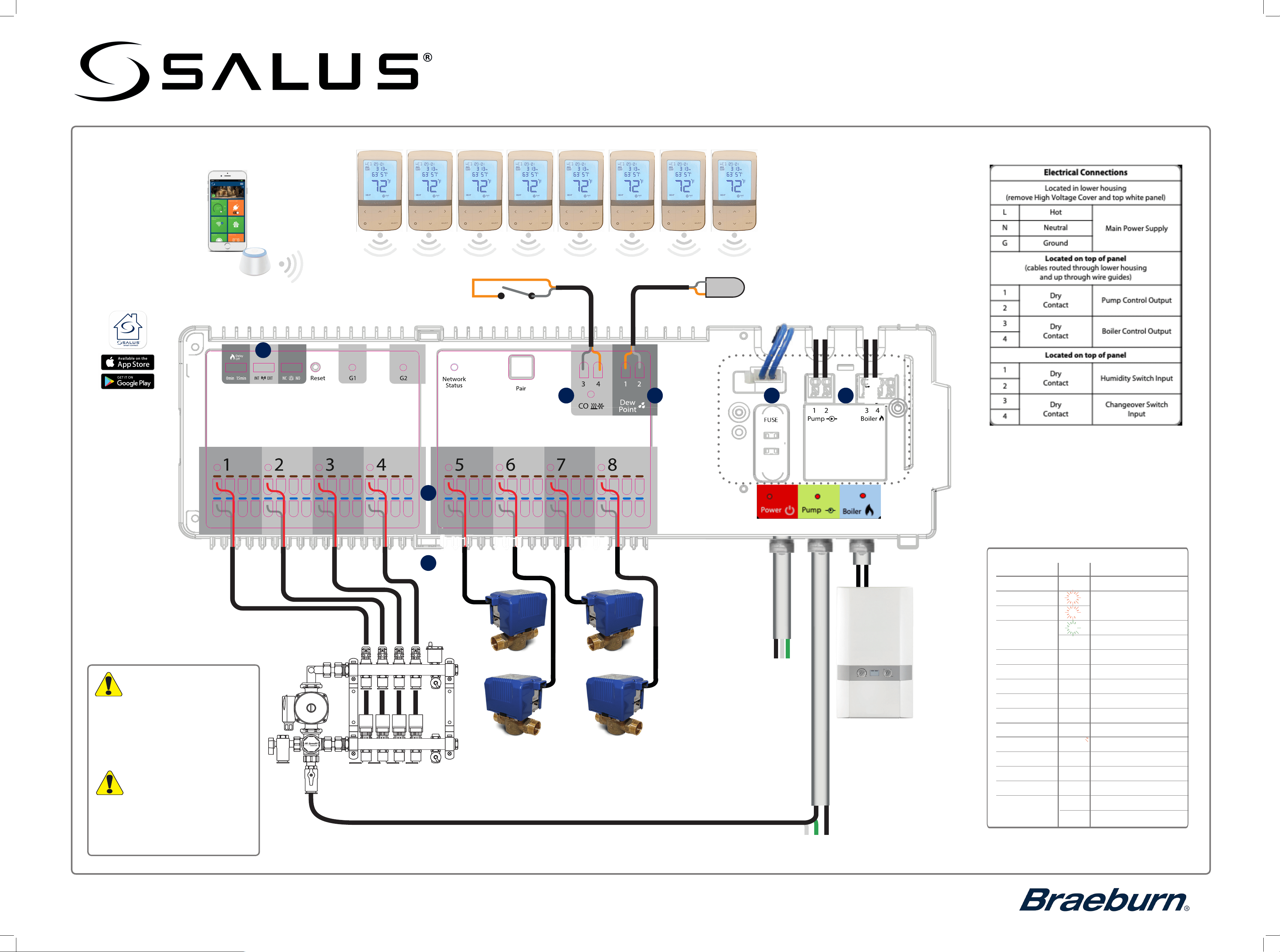
L N G
DRY CONTACTS
ONLY
UNDERFLOOR
HEATING MANIFOLD
Warning
Warning
•
•
Always disconnect power to the
control
before installing or working
on any components. The control
power supply must be properly
grounded.
Remove the High Voltage
cover access to the Boiler
and Pump terminals.
Stephen Wu
2016-11-11
Transparent matt gray(same color and
surface ÿnishing with old KL08 cover)
silk print white
matt surface ÿnishing, same black
color with old KL08 body
warning mark: high
surface ÿnishing
Color Spec
9
7 6
10
5
8
N
G
L
External Power Supply
4 Amp
Heat/ Cool changeover contact (optional)
(Open = heat, closed = cool)
Dew point switch (optional)
salusinc.com Technical Support 1-888-387-2587
120VAC TO UFH PUMP Cables to be supplied by the installer
13
• For professional installation only.
•
•
Observe applicable national and local
electrical codes.
Failure to comply with
requirements,
standards, and regulations could result
in injury, death, or prosecution.
LED indications
Name
Color
Meaning
Power
120V power is On
G1
Identify mode
is active
G2
•
Network Status
Waiting to pair
Connected to network
Zone 1 Status
•
•
•
Zone 2 Status
Zone 2 demand
Zone 3 Status
Zone 3 demand
Zone 4 Status
Zone 4 demand
Zone 5 Status
Zone 5 demand
Zone 6 Status
Zone 6 demand
Zone 7 Status
Zone 7 demand
Zone 8 Status
Zone 8 demand
Pump Pump on
Boiler Boiler on
CO
•
•
•
•
•
•
•
•
•
•
•
•
•
Heating Mode
Cooling Mode
Zone 1
demand
AWRT10RF Wireless Radiant
Thermostat
●
●
Download the App from the
Apple or Google App Store
Note: A Zigbee gateway or coordinator is required to facilitate
communication between the wireless thermostats and
the Valve Relay Control.
The Salus Smart Connect
App provides remote
monitoring and control
from your Apple or Android
mobile device. A desktop
App is also available at
salussmartconnect.com
To access the line
voltage terminals,
remove the top
white panel by
loosening the 2
screws and lifting up
on the left side
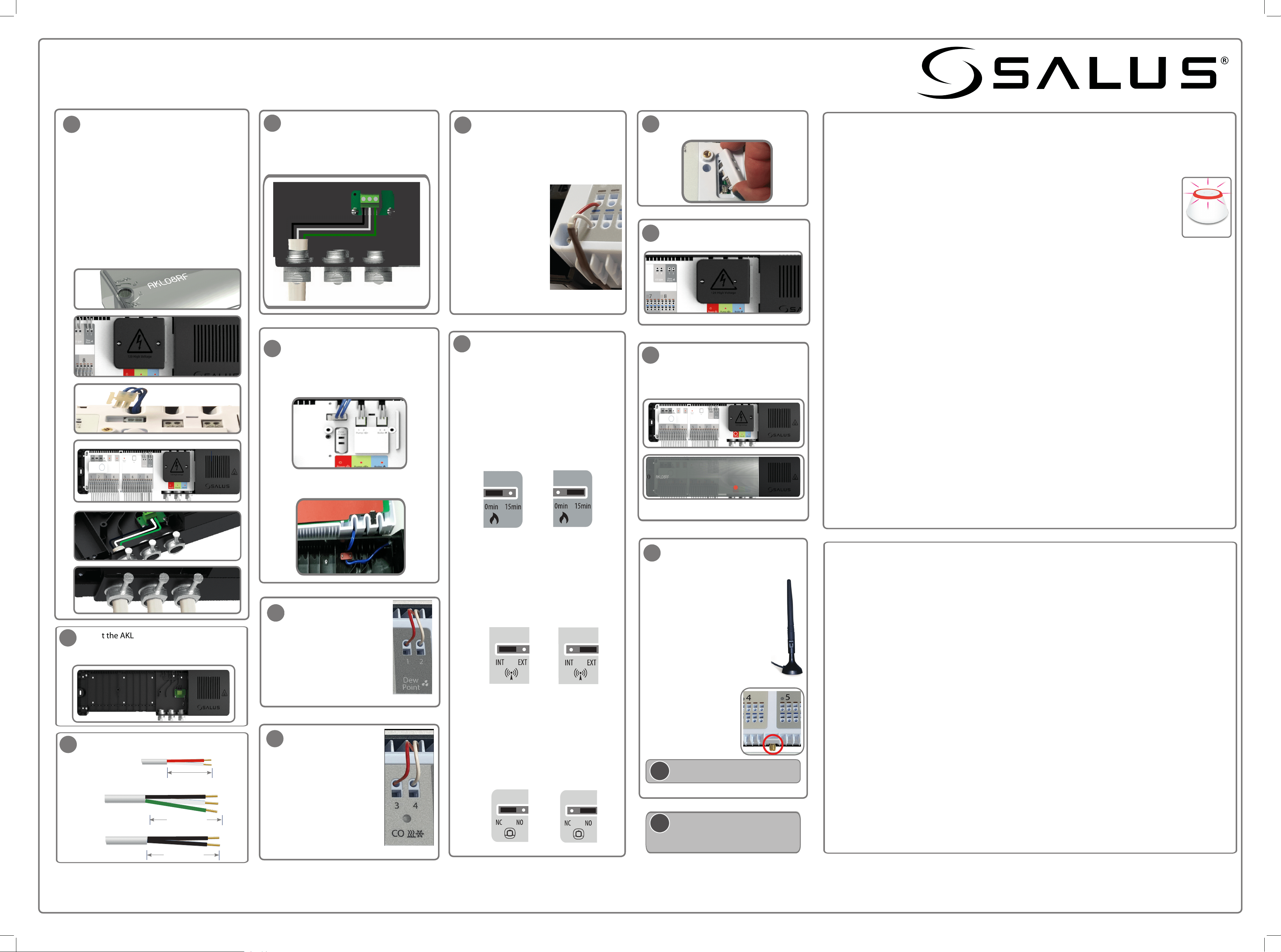
Installing and Connecting the AKL08RF Wireless Valve Relay Control
Install the AKL08RF only in dry and closed interior rooms. Relative air humidity in the room may not exceed 95%.
•
Set the configuration jumpers.
Pump/Boiler On/Off Delay
The pump/boiler on delay is fixed at 3
minutes.
The pump off is also fixed at 3 minutes.
The default setting for the boiler off delay is
0 minutes, but can be changed to 15
minutes by repositioning the jumper as
shown below.
Wireless Antenna
By default the AKL08RF uses an internal
wireless antenna. If it becomes necessary to
use an external antenna (A8RFA), connect the
A8RFA connector to the threaded connector
on the control and reposition the jumper as
shown below. (See step 13)
Actuator Type
The default setting for the type of actuator is
normally closed (NC). To change
this setting
to normally open (NO), reposition the
jumper as shown below.
(Optional)
Insert the wires from
a dry contact humidity
sensor into the Dew Point
terminals 1 and 2.
Connect Actuators and zone valves
Make sure the correct fuse is in place
(4 Amp).
Re-attach the plastic cover. Turn the
screw to the lock position. Switch on
main power supply to the unit.
The red
LED comes on.
Re-attach the High voltage cover and
secure it with two screws.
Connecting the AKL08RF (s) to the Wireless Network
On powering up the AKL08RF, G1, G2 & Network Status LEDs light up then go off, specific zone LEDs sequence
to indicate the firmware version, then the Network Status LED flashes green to indicate it is in pairing mode.
1. Add your AKL08RF(s) to the wireless network.
a. Launch and sign into the Salus Smart Connect App
b. Tap the 3-bar menu icon, tap Settings > Setup Equipment > Scan Devices. Follow
the on-screen prompts to add the AKL08RF to the network.
c. When in Pairing Mode, the LED on the Universal Gateway will flash red. The Network
Status LED on the AKL08RF turns steady green when connected.
d. Repeat the process for each AKL08RF to be added to the system.
e. Once all discovered devices are paired, the Gateway LED will turn blue.
2. Add your thermostats to the wirelss network and pair with the appropriate AKL08RF Zone
a. To identify the AKL08RF number, press Pair for one second. Note the zone number
LED that illuminates green. Zone 1 = WC -1, Zone 2 = WC-2, and so on. The Network
Status LED is used to identify WC-9.
b.
c.
Refer to the instructions that came with the thermostat on how to initiate its Pairing
mode. Initiate
Pairing.
Using the Smart connect App, tap the 3-bar menu icon, tap Settings > Setup Equipment > Scan
Devices. Follow the on-screen prompts to add the thermostats to
the network.
d. Follow the thermostat instructions to set the controller number (step a.) and zone number for each
thermostat.
Checking the System Configuration and Communication (Identify mode)
• Using the Smart Connect App, select the AKL08RF, go to the Device Details Page, and tap
the Identify
button. The AKL08RF and associated devices will start flashing. To exit identify mode tap the button in the
App again.
• On the AKL08RF, press the Pair button for 5 seconds, all devices associated with the AKL08RF will flash. To exit
the Identify mode press the Pair button for 5 seconds, otherwise it will timeout after 10 minutes.
Resetting the AKL08RF to factory defaults
• You can remove your devices
using the Smart Connect App by going to the devices Device Details page and
tapping the Remove device link at the bottom of the page.
• To delete all devices connected to the AKL08RF and remove it from the network, press and hold the Pair
button on the AKL08RF for 15 seconds. The G1 and G2 LEDs turn from flashing red to solid red then go off.
Remove power for 10 seconds and restore.
Antenna protective cap
Connect 120VAC power supply
Connect wires to the L, N & G terminals
• L is for Hot
• N is for Neutral
• G is for Ground
4
8
9
10
11
12
13
Connect the pump and boiler cables.
• Press the terminal button, insert the
wires and release the button.
• Confirm that the wires are securely
connected.
Ensure the wires fit neatly in the grooves.
5
24
VAC
7
24
VAC
A. Remove the plastic cover by turning the
screw 90
o
to the Unlock position.
B. Remove the High voltage cover.
C. Detach the 24V supply connection.
D. Remove the white terminal cover to access
the power connections.
E. Insert wires for the Power, Pump and Boiler
and fasten securely.
F. Use cable clamps or strain reliefs (not
included) for a 120VAC power supply
system. After placing the wires through the
wire cable clamps, secure them by
tightening the screws.
A.
B.
D.
E.
C.
1
F.
Mount the AKL08RF base to a flat surface. If
mounted on a stud wall, extra support may
be required.
110mm/4.33in
Pump
100mm/3.93in
Connecting an External Antenna
a. Disconnect power.
b. Remove the protective cap
from the antenna connection on
the bottom of the AKL08RF.
c. Screw the antenna into the
AKL08RF
d. Set the Wireless Antenna jumper
to EXT. (See step 9)
e. Reconnect power, the AKL08RF
will now use the external antenna
i
The antenna (A8RFA) is sold separately.
110mm/4.33in
i
Use a soft dry cloth to clean the AKL08RF
housing. Do not use solvents or
aggressive cleaning agents.
salusinc.com Technical Support 1-888-387-2587
(Optional)
Insert the wires from a
dry-contact change-over
switch to change from
heating to cooling mode.
Open for Heating mode
(red LED)
Closed for Cooling mode
(blue LED)
• Reattach the 24V supply
connection.
• Reattach the white cover to the
control and secure it with two
screws.
This equipment has been tested and found to comply with the limits for a Class B digital device, pursuant
to Part 15 of the FCC Rules. These limits are designed to provide reasonable protection against
harmful interference in a residential installation. This equipment generates uses and can radiate radio
frequency energy and, if not installed and used in accordance with the instructions, may cause
harmful interference to radio communications. However, there is no guarantee that interference will
not occur in a particular installation. If this equipment does cause harmful interference to radio or television
reception, which can be determined by turning the equipment off and on, the user is encouraged to try to
correct the interference by one or more of the following measures:
• Reorient or relocate the receiving antenna.
• Increase the separation between the equipment and receiver.
• Connect the equipment into an outlet on a circuit different from that to which the receiver is connected.
• Consult the dealer or an experienced radio/TV technician for help.
Changes or modifications not expressly approved by the party responsible for compliance could void the user’s
authority to operate the equipment.
This device complies with part 15 of the FCC Rules. Operation is subject to the following two conditions: (1) This
device may not cause harmful interference, and (2) this device must accept any interference received, including
interference that may cause undesired operation.
This device complies with Industry Canada’s license-exempt RSSs. Operation is subject to the following two
conditions:
1) This device may not cause interference; and
2) This device must accept any interference, including interference that may cause undesired operation of
the device.
Le présent appareil est conforme aux CNR d’Industrie Canada applicables aux appareils radio exempts
de licence. L’exploitation est autorisée aux deux conditions suivantes :
1) l’appareil ne doit pas produire de brouillage, et
2) l’utilisateur de l’appareil doit accepter tout brouillage radioélectrique subi, même si le brouillage est
susceptible d’encompromettre le fonctionnement.
120VAC
Power
Cable Preparation
L
N G
LNG
• Insert the wires
• for the actuator/
valve in the
brown and blue
holes or the
desired zone.
• You can add up
to 4 actuators or
1 motorized
valves for each
zone.
Note: After all devices have been deleted from the wireless network, they will need to be reinstalled.
Refer to the instruction manuals.
22
6
33
•
Actuator or
Motorized valve
●
●
Braeburn Systems LLC • 2215 Cornell Avenue • Montgomery, IL 60538
©2025 Braeburn Systems LLC • All Rights Reserved.
AKL08RF-100-03-EN
