24
VAC
FUSE
H
HN
ON OFF
⬆
FUSE
24
VACCCCCCCCC
www.salusinc.com Technical Helpline
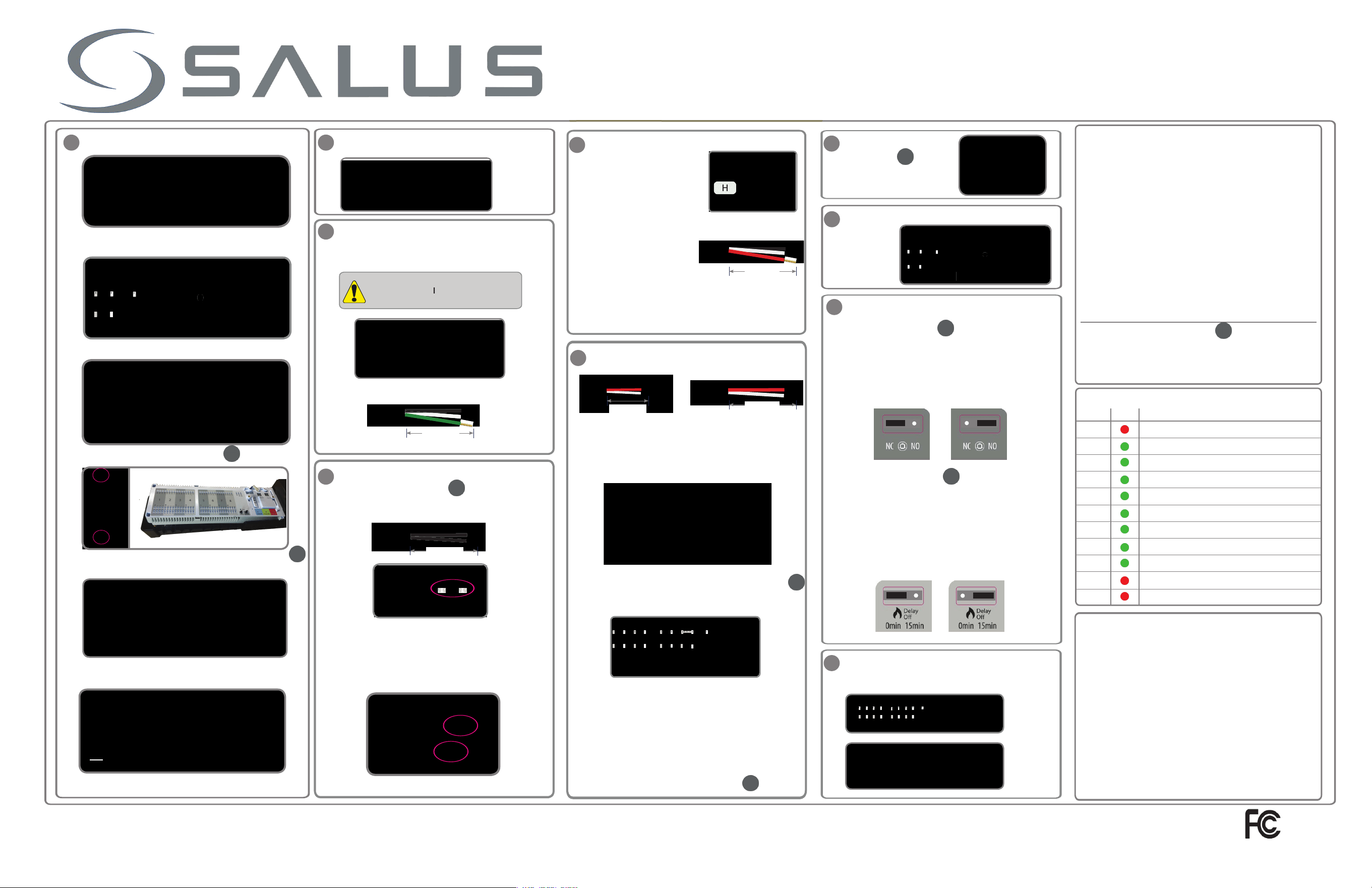
Remove the white
Remove the white
terminal
plate in order
to reach the
to reach the
power cord terminals for the
power cord terminals for the
120VAC supply.
Loosen the cable clamps
(not included)
nsert the wires for the power, boiler and pump
nstall or route the wires to their desired locations
Tighten the cable clamps to secure the wires
See section 1 for more info.
Installation and Wiring Guide
This product must be fitted by a competent person,
and installation must comply with the guidance,
standards and regulations applicable to the country
or state where the product is installed. Failure to
comply with the requirements of the relevant
guidance, standards and regulations could lead to
injury, death or prosecution.
Always isolate the AC main supply before installing
or working on any components that require
120VAC 60Hz supply.
The ground terminals on the AKL08 are for ground
connections only. These terminals provide no earth
protection.
The
cable clamps
used for securing
the wires are sold separately.
i
Remove the High
V
oltage
cover for access to the Boiler
and
P
ump terminals.
i
i
If you are mounting the Zone
W
iring
C
enter
on a stud wall, extra support may be required.
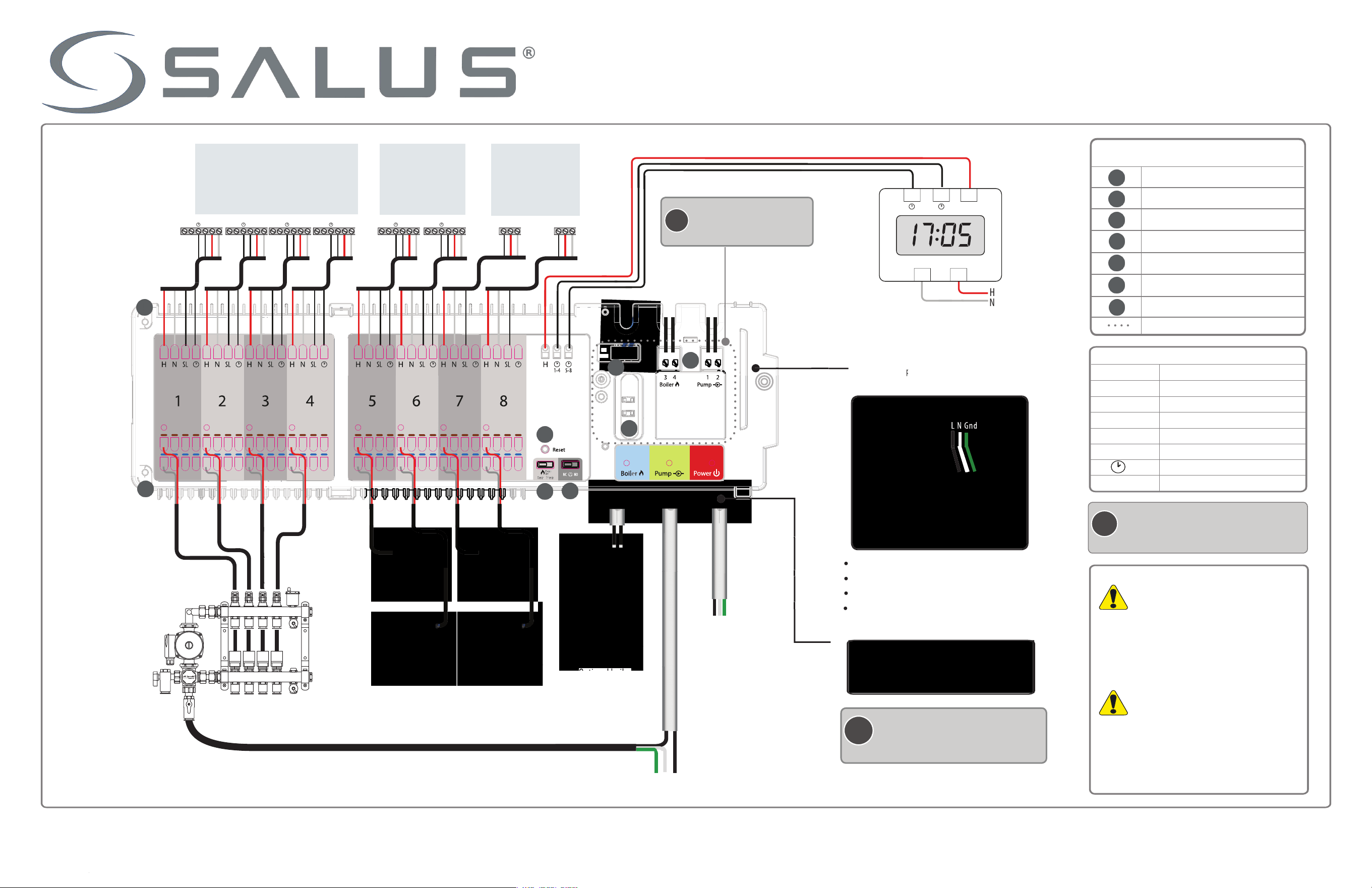
L Line connection
H / R
N
nd
Ground
S1 Floor sensor
Night Set Back
W / SL / ⬆ Switched contact
R
AKL08 IWG-ENv4
ptional eternal clock
AKL08 one Relay Controller / iring Center
Terminal late Screw
High Voltage Cover
Fuse
ump Boiler Connections
Reset Button
N / NC Actuator umper
Boiler Delay Jumper
2V ower Connection
ower (2 VAC)
Neutral or Common
R C ⬆ R C ⬆ R C ⬆ R C ⬆ R C ⬆ R C ⬆ R C ⬆ R C ⬆
⬆
⬆
⬆
⬆
⬆ WW
C
Common
NSB
A
A
A
B
C
D
E
F
G
B
C
D
E
F
G
Installation and Wiring Guide
Color
ower AKL08 is supplied with 120VAC power
one 1
ump
ump contact closed
Boiler
Boiler contact closed
A.
B.
E.
Re-attach the High Voltage cover and secure it with
two screws.
Ensure the pump and boiler wires are correctly routed
through the grooves in the back plate and white terminal
plate.
The default actuator type supported by the boiler and
pump relays is normally closed (NC). To change to
normally open (NO), carefully remove the jumper and
reinsert it in the other position as shown below. The
jumper does NOT change the zone output behavior.
The thermostat must support the type of actuator used.
f using slave thermostats
with the NSB lines connected,
an eternal clock dry contact
can control the NSB function
of the slave thermostats.
Loosen the screws on the green terminals then insert
the power wires and fasten to secure.
/.33
/.33
/.33
Use
powe
r
that are
suitable
for your
system.
/3.
H
Remove the plastic cover by rotating the retainer 90
0
to the
Unlock position.
Remove the High Voltage cover by loosening the retainer screws.
C.
isconnect the 24VAC supply connection.
D.
Loosen the two screws on the left of the white terminal plate,
then lift to remove for access to the power cord terminals.
nstall the appropriate cable clamps (purchased separately) and
insert the power wires and optional pump and boiler wires.
Mount the AKL08 to the wall or a suitable location
using the mounting holes.
connections.
ll the wires for the thermostats should be fixed in
the grooves at the top, under the white terminal plate.
nfirm the presence of a
Amp fuse
Replace the plastic cover and reattach it by turning the
retainer to the Lock position. Switch on the main power
supply to the unit. The red ower LE will turn on.
emand from zone 1 thermostat actuator(s) active
one 2
one 3
one
one
one 6
one 7
one 8
Boiler/Pump
The pump and boiler n delay and the pump ff delay are
fied at 3 minutes in the software and at 0 in the terminal.
The n delay starts when any zone is turned on and stays
on. The ff delay starts when the last zone is turned off.
The boiler ff delay is controlled by a jumper and can be
either 0 or 1 minutes. To select the desired delay, place
the jumper in the position corresponding to the desired
delay time.
Technical Helpline
AKL08 one Relay Controller / iring Center
emand from zone 2 thermostat actuator(s) active
emand from zone 3 thermostat actuator(s) active
emand from zone thermostat actuator(s) active
emand from zone thermostat actuator(s) active
emand from zone 6 thermostat actuator(s) active
emand from zone 7 thermostat actuator(s) active
emand from zone 8 thermostat actuator(s) active
.
se the L0 relay controller to simply and safely connect
thermostats to their corresponding thermal actuators or
motorized valves in three possible configurations
One thermostat for each zone (8 thermostats in total)
Single group with one master SALUS
thermostat and up
to 7 slave thermostats.
Two groups (G1 and G2) with 1 master thermostat and up
to 3 slave thermostats per group.
Tighten the cable clamps to secure the wires.
qffBgv
f.gv
gff.qg
fqgf
f f .v g
f . f q f
fvgq
ffgfffg
:
gfvf
v'q.
v f . j fg
:vffv
fvgf.
Bg3.
éqBfàB3.
Strip the thermostat, actuator and valve wires and
cables to the appropriate lengths.
Bend and insert the thermostat wires into the round
holes at the top of the AKL08 white terminal plate.
For group functions, be sure to connect the NSB
control line of the master and slave thermostats. For
standalone thermostat operation, do NT connect the NSB
control line of the thermostat.
. p to actuators or motorized valves can be
controlled by each zone.
Reconnect the 2VAC power supply.
f using 1 master and 7 slave
thermostats, and all zones are to
follow the NSB of the master,
place a jumper wire between
the NSB 1 and NSB 8 terminals.
ress the terminal button with a small screwdriver.
nsert the wire, then release the button.
Strip the boiler and pump wires to the appropriate length.
Run the thermostat cables in the slots on the back
plate for the appropriate zone.
Reattach the white terminal plate to the back plate
and secure it with the two screws on the left.
1.
You can have up to actuators or motorized valves per zone.
2.
You can use L thermostats or any other thermostat
that is compatible with the system.
3.
Mae sure that the thermostats, actuators and motorized
valves are all .
e recommend the use of Salus Thermostats.
or more details please visit our website www.salusinc.com
To perform a factory reset on the AKL08, locate the reset
button to the right of the boiler delay jumpers. sing a
suitable tool, press the reset button and release. The AKL08
should now be set to factory defaults.
Bend and insert the actuator and motorized valve
wires into the round holes at the bottom of the plate.
Connect the H terminal to the shared contact of the
clock output.
/.33
External NSB Clock
Connect the other clock output contact to the desired
NSB group of the slave thermostats, 1, 8, or both.
A
B
C
D
E
F
G
A
G
vg.
qv.
qfffv
.
/f.

