SMC-UM-SC824ZB-202001v1_2020-2-28
SC824ZB Smart Relay – Low Voltage
User Manual

ii
Device Overview
SC824ZB Smart Relay – Low Voltage User Manual
Contents
Section Page
1 Introduction
Device Overview............................................................................ . . . . . 1-1
In The Box. ................................... . . . . . . . . . . . . . . . . . . . . . . . . . . . . . . . . . . . . . . . . . . . . . . . . . . . 1-1
Tools Required /Optional .................... . . . . . . . . . . . . . . . . . . . . . . . . . . . . . . . . . . . . . . . . . . . . . . . . . . . . 1-1
2 Installation
Installation using Wall Mount with Cover..... . . . . . . . . . . . . . . . . . . . . . . . . . . . . . . . . . . . . . . . . . . . . . . . . . . . . 2-1
Installation with Surface Mounting Adhesive. . . . . . . . . . . . . . . . . . . . . . . . . . . . . . . . . . . . . . . . . . . . . . . . . . . . . 2-2
3 Joining/Pairing Instructions
Joining the network for SALUS Smart Home Control Only . . . . . . . . . . . . . . . . . . . . . . . . . . . . . . . . . . . . . . . . . . . . . . . . . . . . 3-1
Pairing with AWRT10RF Wireless Radiant Thermostat . . . . . . . . . . . . . . . . . . . . . . . . . . . . . . . . . . . . . . . . . . . . . . . . . . . . 3-3
4 Operation & Setup
Local Relay Operation ....................... . . . . . . . . . . . . . . . . . . . . . . . . . . . . . . . . . . . . . . . . . . . . . . . . . . . . 4-1
Schedule Setup with SALUS Smart Home Application . . . . . . . . . . . . . . . . . . . . . . . . . . . . . . . . . . . . . . . . . . . . . . . . . . . . 4-1
Setup Options .............................. . . . . . . . . . . . . . . . . . . . . . . . . . . . . . . . . . . . . . . . . . . . . . . . . . . . . 4-2
5 Factory Defaults
Resetting Factory Defaults Settings .......... . . . . . . . . . . . . . . . . . . . . . . . . . . . . . . . . . . . . . . . . . . . . . . . . . . . . 5-1

iii
Device Overview
SC824ZB Smart Relay – Low Voltage User Manual
Safety Instructions
Safety Instructions
Please read these instructions carefully BEFORE INSTALLING and using the SC824ZB Smart Relay.
Keep this guide in a safe place for future reference.
• Installation and repairs are to be performed by a qualied contractor in strict accordance with
the requirements of state and local regulating agencies. In the absence of local requirements,
follow ANSI/NFPA 70, National Electric Code.
• The SC824ZB Smart Relay uses a 24 VAC power source. DO NOT CONNECT this device to supply
voltages above 30 VAC.
• DO NOT expose the Smart Relay to voltage uctuations of more than 10% (±2.4 VAC)
• DO NOT install the SC824ZB in a bathroom or area of excessive moisture.
• DO NOT allow the Smart Relay to get wet.
• DO NOT expose the SC824ZB Smart Relay to temperatures below -20°F (-4°C) or
above 122°F (60°C).
• DO NOT allow the Smart Relay to operate in temperatures below 32°F (0°C) or
above 113°F (45°C).
• DO NOT use solvents or aggressive cleaning agents to clean the device. A dry, soft cloth
is recommended.
1-1
Device Overview
Section 1
SC824ZB Smart Relay – Low Voltage User Manual
Introduction
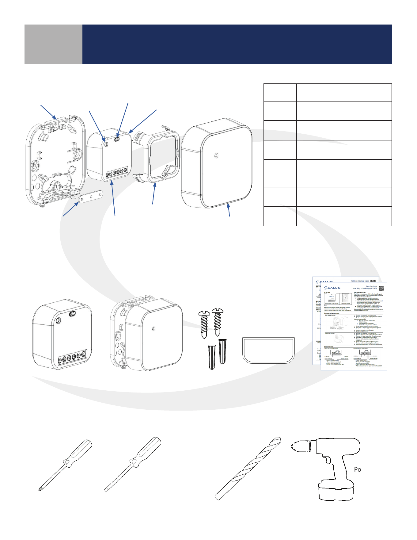
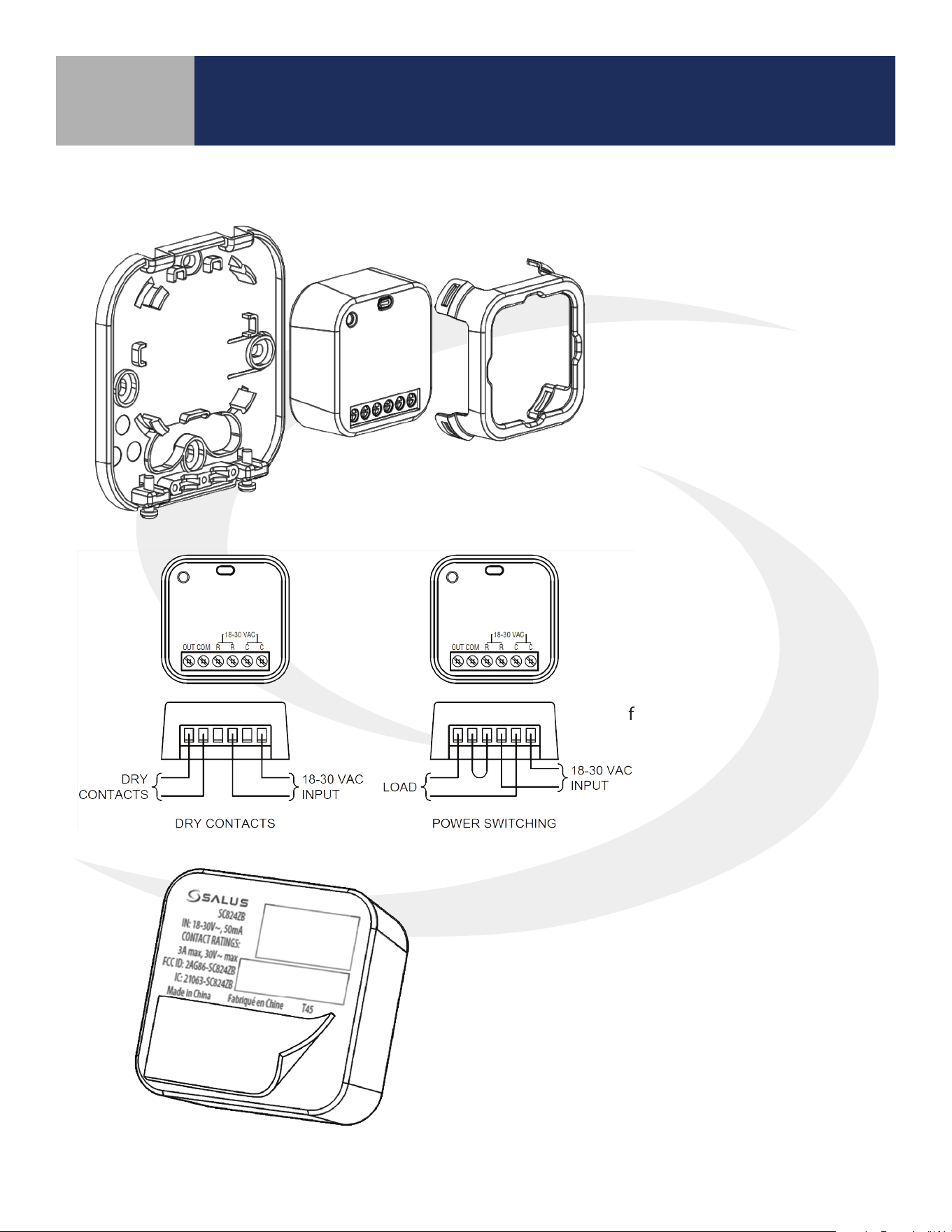
Item Description
Wall
Plate
Allows surface mounting of
the SC824ZB Smart Relay
Relay
Retainer
Attaches the SC824ZB to the
Wall Plate
Multi-
Button
For pairing and identification
of the SC824ZB Smart Relay
Strain
Relief
Prevents damage to the
wiring terminals from
external forces
Terminal
Strip
For connecting relay contacts
and power supply
Status
LED
Provides status feedback
about the SC824ZB Relay
In The Box
BEFORE BEGINNING installation, conrm that all parts are present in the package:
SC824ZB Smart Relay
-Low Voltage
Wall Mount
with Cover
Mounting
Screws
Installation
Quick-start Guide
English / French
Tools Required
Wall Plate
Status LED
Multi-Button
SC824ZB Smart
Relay - Low Voltage
Front CoverStrain Relief Terminal Strip
Relay Retainer
Double-sided
Adhesive
#1 Phillips
Screwdriver
1/8” Flat
Screwdriver
Power Drill
3/16” Drill Bit
Optional Tools
Device Overview
2-1
Device Overview
Section 2
SC824ZB Smart Relay – Low Voltage User Manual
Installation
Installation Using Wall Mount With Cover
• Locate the Smart Relay in or near the location that it will be installed to account for radio interference
• Avoid locations where exposure to splashing water, accumulation of dirt/grease or where temperatures
exceed 104°F (40°C)
Step 3. Place SC824ZB Smart Relay in the space
provided on the wall plate and use the retaining clip
to hold it in place. Tighten the strain relief to hold
wires securely.
Step 4. Remove the knockout portion of
the cover to allow wires to pass through.
Assemble the enclosure cover, making sure
the wires don’t interfere with proper closure.
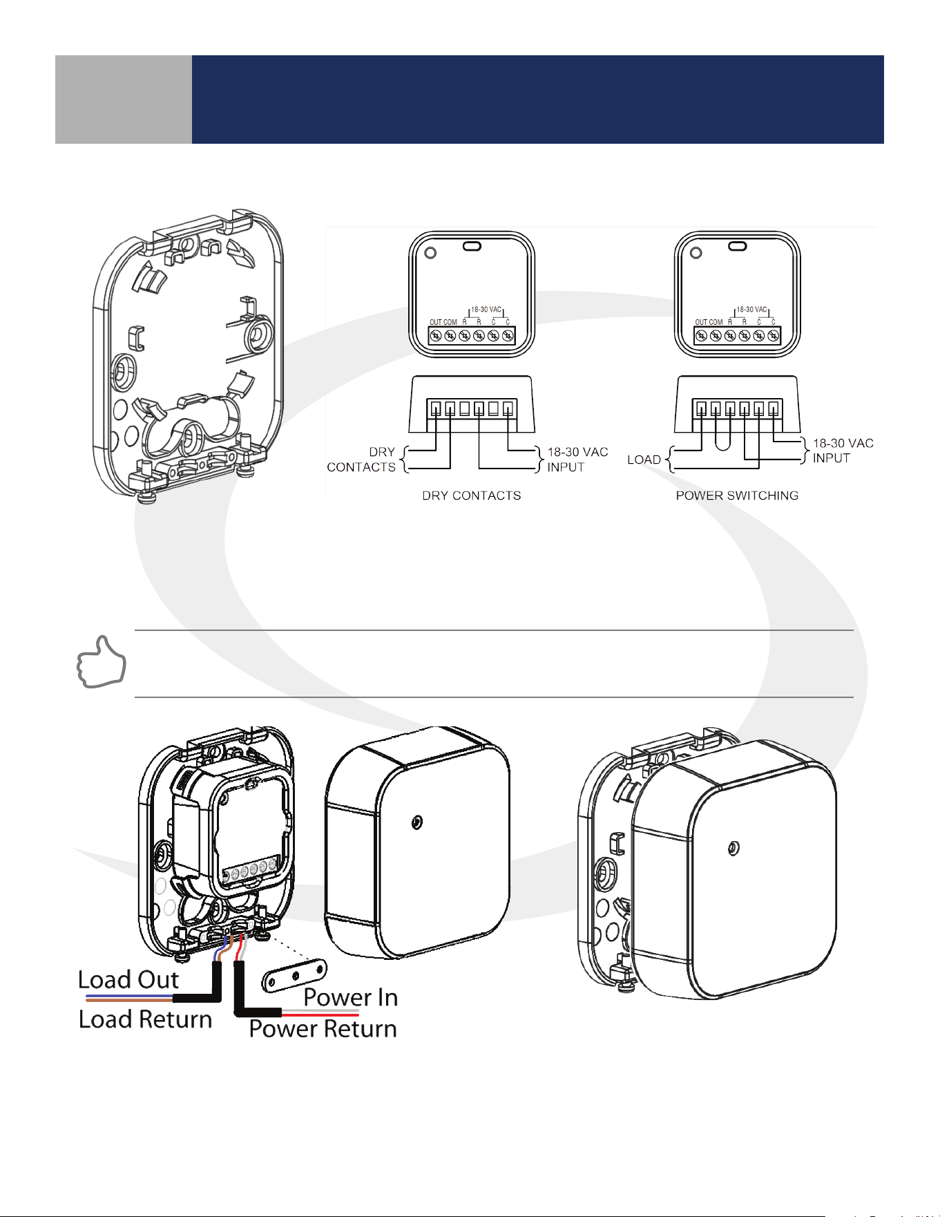
Step 2. Wire the SC824 Smart Relay using the appropriate diagram
above. Run wires through the strain relief before proceeding to
the next step. For a power switching application, a jumper must be
applied between R & COM.
Step 1. Attach the wall plate
(if used) for the Smart Relay
in a suitable location using
the screws included.
2-2
Installation With Surface Mounting Adhesive
Step 2. Wire the relay using the
appropriate diagram. Be sure to
use a jumper between R & COM
for Power Switching.
Step 1. Remove Smart Relay
from Mounting Kit.
Step 3. Remove the white backing with no text
from the adhesive provided.
Step 4. Apply the adhesive to the back of the
Smart Relay at the bottom below the text.
Step 5. Remove the lettered backing from the
double-sided adhesive and apply the relay to
the desired surface.
Device Overview
Section 2
SC824ZB Smart Relay – Low Voltage User Manual
Installation
3-1
Device Overview
Section 3
SC824ZB Smart Relay – Low Voltage User Manual
Joining/Pairing Instructions
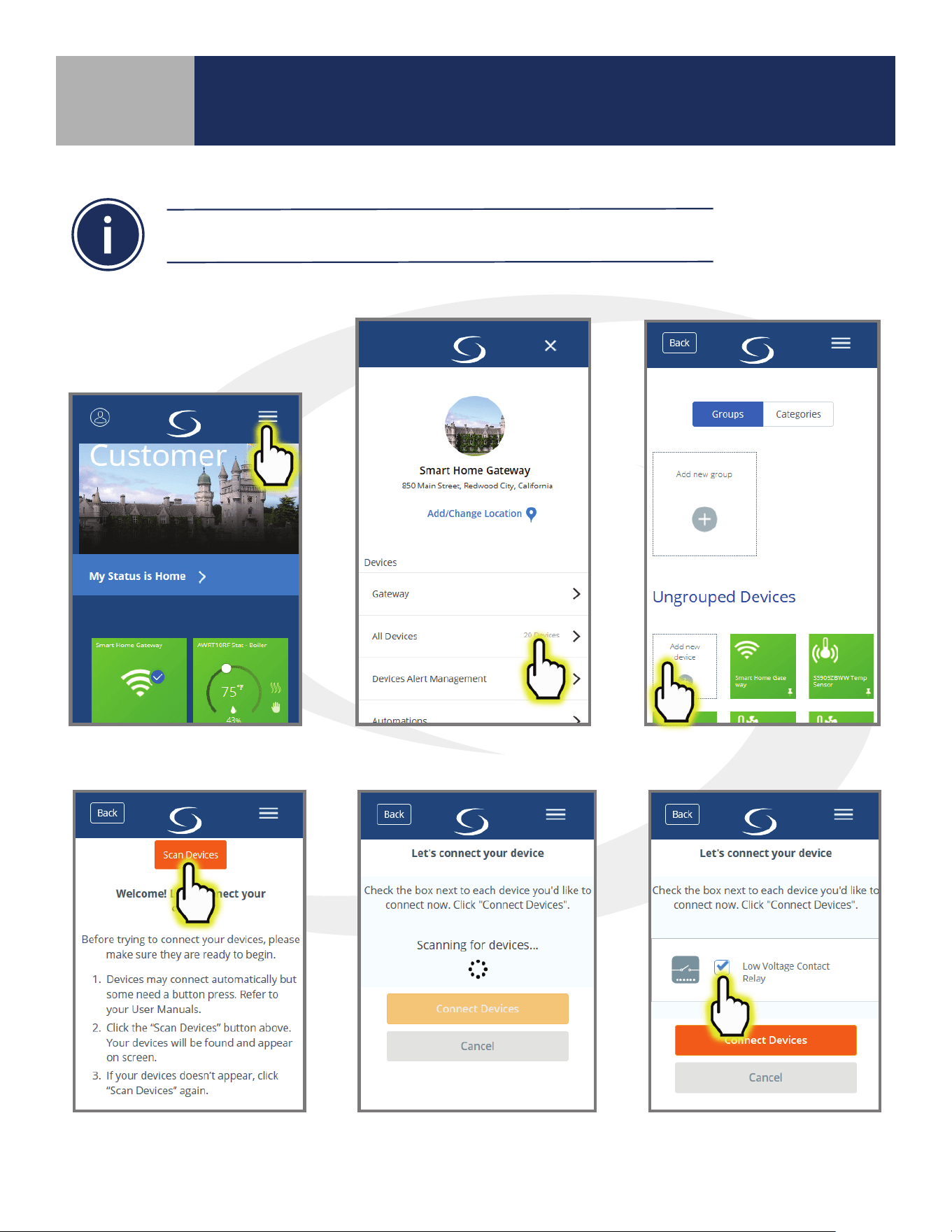
Joining the Network for SALUS Smart Home Control Only
Step 3. Press "Scan Devices."
After pressing “Scan for Equipment”,
the SALUS Smart Home application
scans for devices.
Step 4. Check the box
for the Smart Relay and
press “Connect Devices”.
Step 1. Be sure that there is power applied to the SC824ZB Smart Relay and the Status LED is repeating a sequence
of 3 red ashes then pause.
Be sure the Smart Relay is located at or near its intended location to account for
potential radio interference.
Step 2. Open the SALUS Smart Home application, select the drop-down menu from the upper
right of the screen and select: All Devices Add New Device
3-2
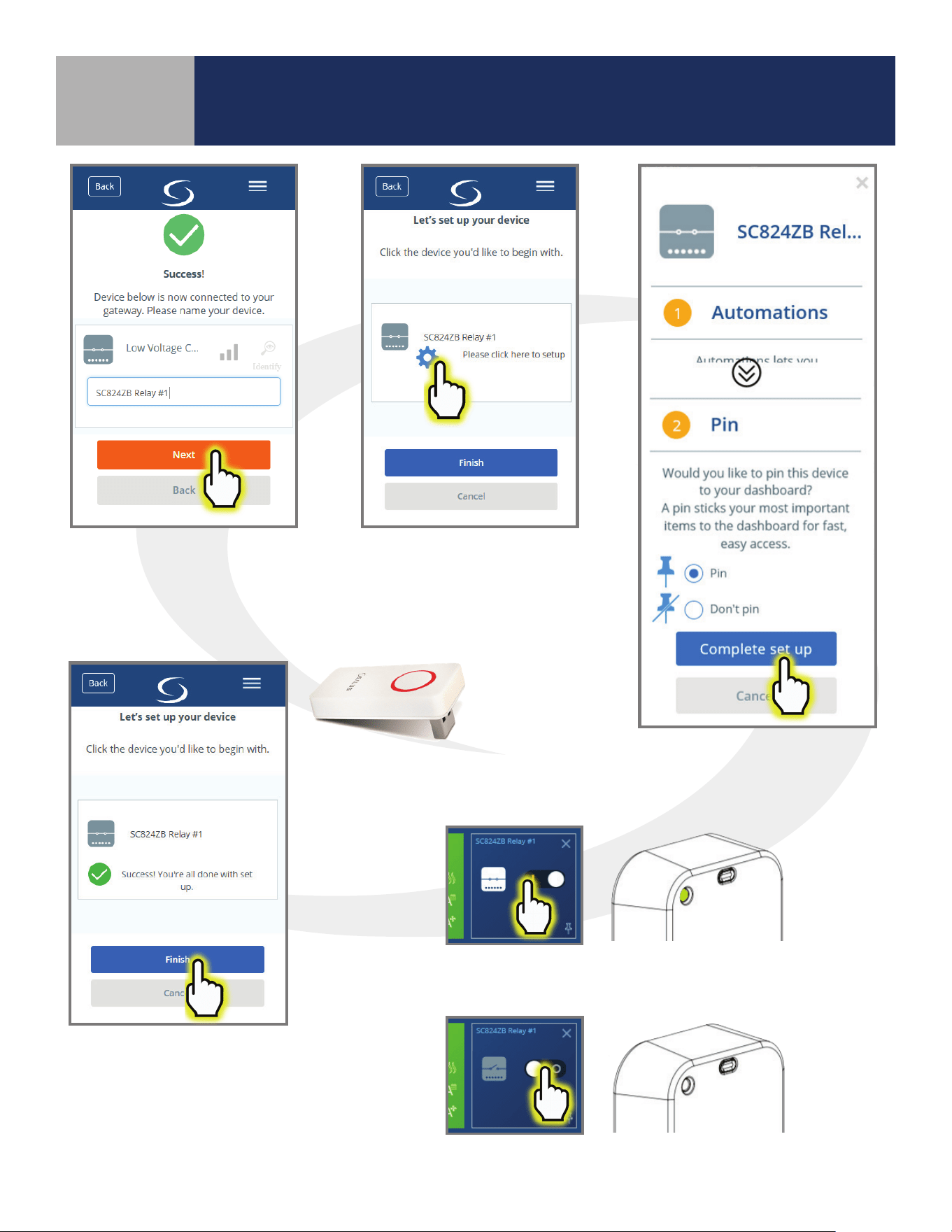
Step 5. Enter a unique
descriptive name for each
Smart Relay to easily identify
each device. Press “Next”.
Step 6. Press “Please click
here to setup”.
Step 7. Press “Complete set
up” to continue
Step 8. Press Finish to
complete pairing.
In case of a weak wireless signal, an
AE10RF Wireless Repeater may be
required.
Device Overview
Section 3
SC824ZB Smart Relay – Low Voltage User Manual
Joining/Pairing Instructions
Step 9. Using the SALUS Smart Home application, power the relay
and make sure the Status LED is green.
Step 10. Switch o the relay and make sure the Status LED goes o.
3-3
Device Overview
Section 3
SC824ZB Smart Relay – Low Voltage User Manual
Joining/Pairing Instructions
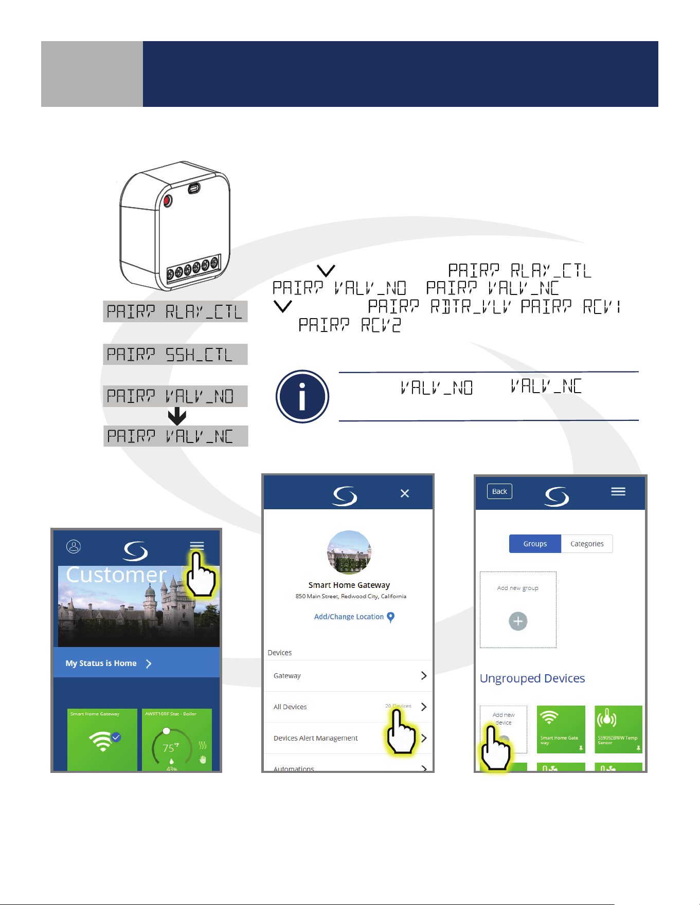
Pairing with AWRT10RF Wireless Radiant Thermostat
Step 1. Be sure there is power applied to the SC824ZB Smart Relay and
the Status LED is repeating a sequence of 3 red ashes. If the Smart
Relay is not ashing as described, reset the device using the procedure
described in Section 5.
Step 2. Prepare the AWRT10RF Thermostat by inserting the batteries.
Use the
key to change from to
or . Using only the
bypasses the ,
and
options. If the required options aren’t
displayed, refer to the AWRT10RF IOM for support.
Step 3. Open the SALUS Smart Home application, select the drop-down menu from the upper
right of the screen and select: All Devices Add New Device
Only the and options
can be used with the SC824ZB Smart Relay.
3-4
Device Overview
Section 3
SC824ZB Smart Relay – Low Voltage User Manual
Joining/Pairing Instructions
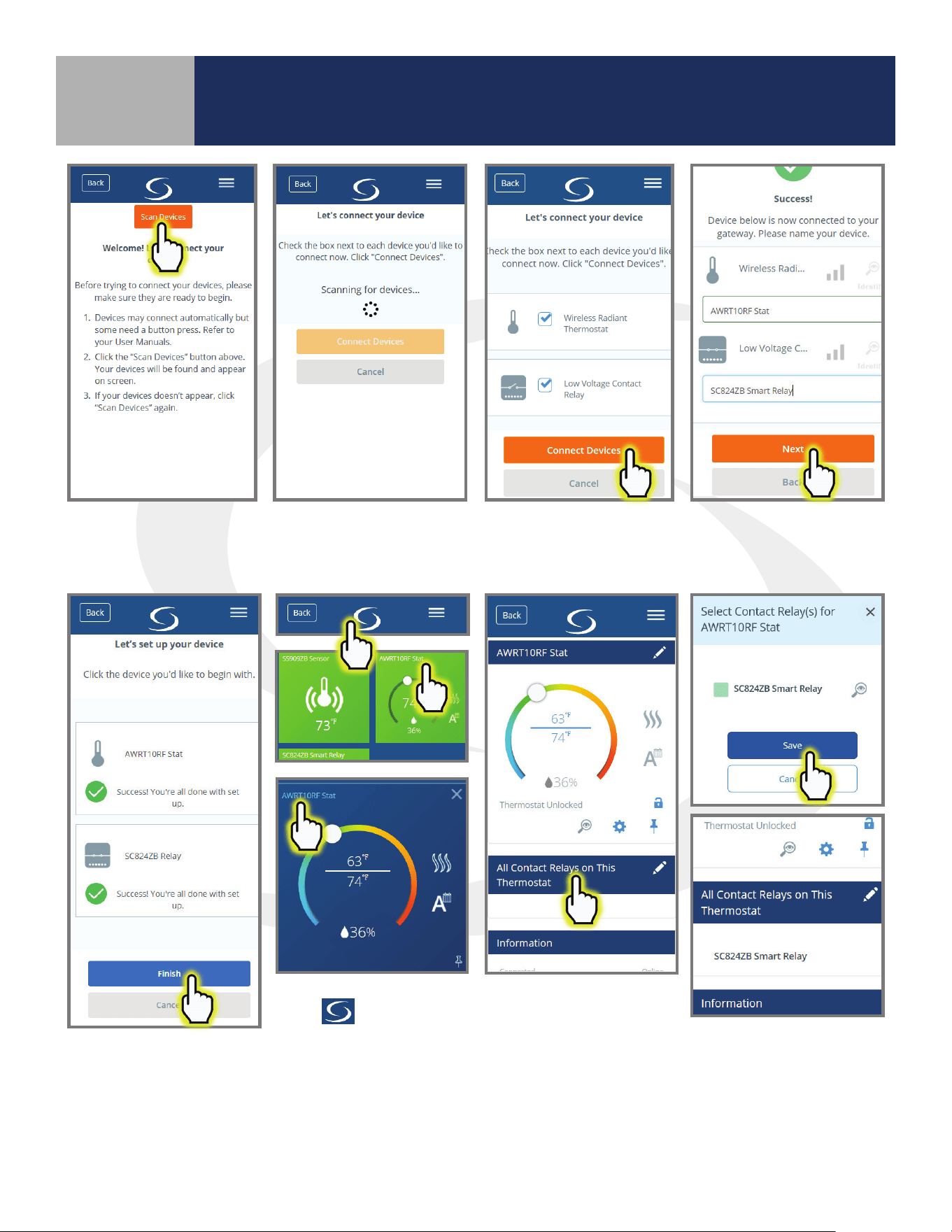
Step 4. Press Scan Devices. Scanning for devices is
then displayed while the signals are located.
Step 5. Check boxes for the
Smart Relay and the Wireless
Radiant Thermostat. Press
Connect Devices.
Step 6. Give each device a
unique descriptive name.
Press Next.
Step 7. After choosing set-
up options, press Complete
set up then Finish.
Step 8. Press the SALUS
Logo
to return to the
Dashboard. Choose the
AWRT10RF Tile then choose
the title in the upper left
corner.
Step 9. Choose All
Contact Relays on
This Thermostat.
Step 10. Be sure that the
box(es) next to the Smart
Relay(s) that will be controlled
by the AWRT Thermostat are
green and press Save.
All associated relays will be listed on the AWRT10RF Set up menu and they will be activated when the Thermostat
calls for heat.
4-1
Device Overview
Section 4
SC824ZB Smart Relay – Low Voltage User Manual
Operation & Setup
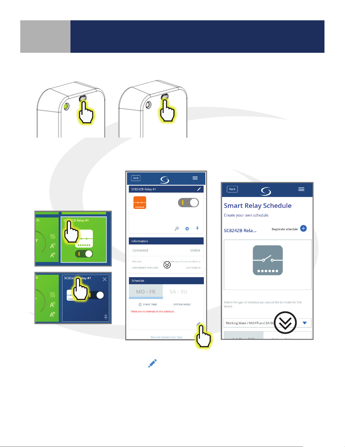
Schedule Setup - SALUS Smart Home Application
Step 1. Select the SC824ZB icon
from the SALUS Smart Home
dashboard. After the tile ips,
choose the device name in the
upper left.
Step 2. Scroll to
“Schedule” and choose
the
icon.
Step 3. Scroll down to view
the schedule types.
Local Relay Operation
To operate the valve locally, without
the SALUS Smart Home app, press
and release the Multi-Button.
4-2
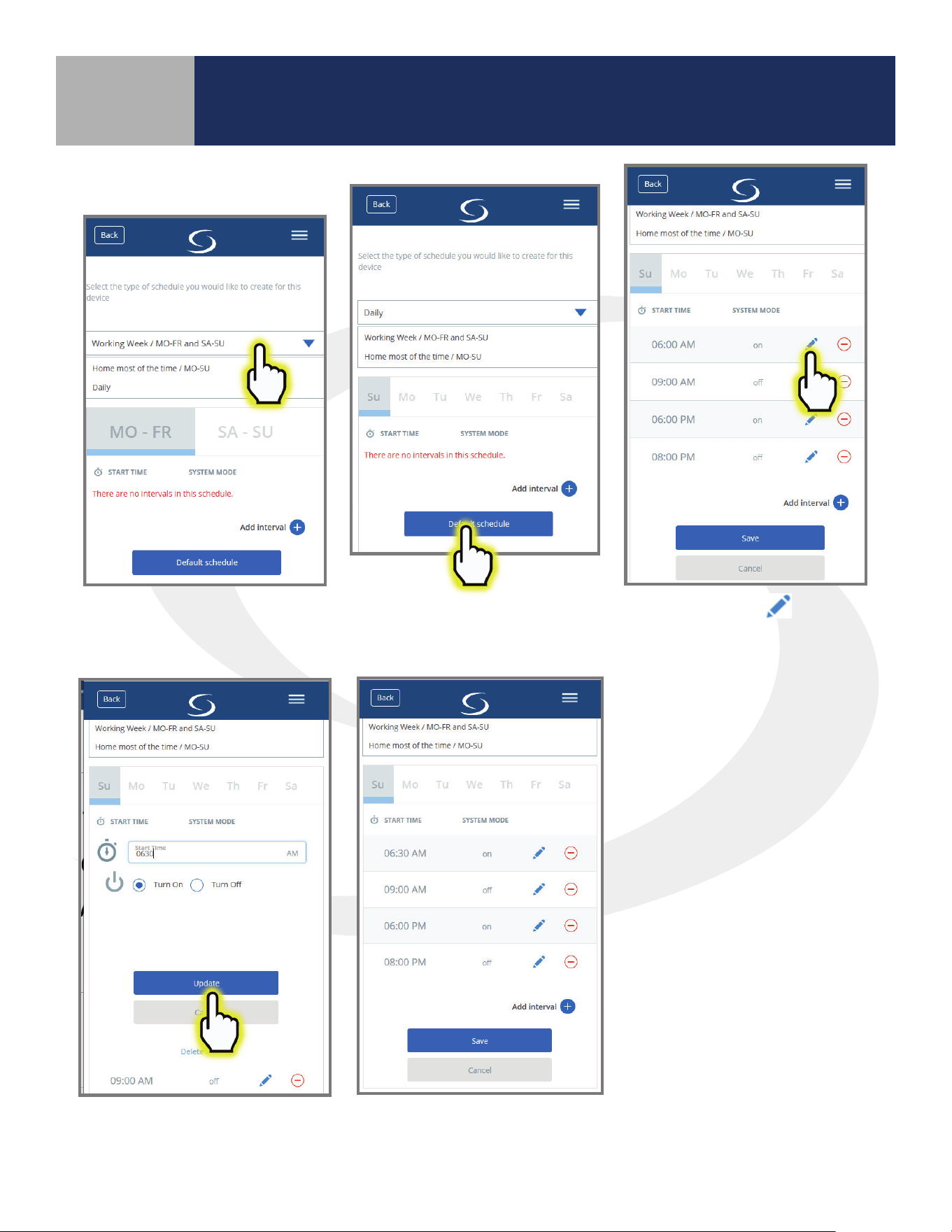
Step 4. Choose the drop-down
menu and select the desired
schedule type.
Step 5. Choose “Default
schedule” to start with a basic
schedule format.
Step 6. Click the
icon
next to any interval to change
values.
Step 7. Make the desired
changes. Then click “Update”.
Make further changes as desired.
The relay will switch on and o
according to the schedule.
Setup Options
Device Overview
Section 4
SC824ZB Smart Relay – Low Voltage User Manual
Operation & Setup

5-1
Device Overview
Section 5
SC824ZB Smart Relay – Low Voltage User Manual
Factory Defaults
Resetting Factory
Defaults
Step 1. Select the SC824ZB icon
from the SALUS Smart Home
dashboard. After the tile ips,
choose the device name in the
upper left.
Step 3. Notication that the
Sensor will be removed is
displayed. Press “Delete” to
continue. The SC824ZB Icon
will be removed from the
application.
Step 4. Press and hold Multi-Button until Status LED
turns red. Continue holding the button until the LED
begins blinking.
Step 5. Release the button and then briey
disconnect power.
Step 6. Observe the LED and be sure it repeats a
sequence of 3 red ashes followed by a pause while
it is searching for a network.
At this point, the valve has been reset to factory default
settings and will respond to pairing requests.
Step 2. Scroll to the bottom
of the next screen and select
“Remove shared smart relay”

SMC-UM-SC824ZB-202001v1
SALUS North America, Inc.
850 Main Street
Redwood City, CA 94063
(888) 387-2587 | [email protected] | www.salusinc.com
Copyright © SALUS North America, Inc. 2019