BOILER
AUX XX ZONE1 E/S
TRANSFORMER
LN
GROUND
LN
PUMP2
LN
PUMP3
LN
PUMP4
LN
PUMP5
LN
PUMP6
LN
PRIMARY
PUMP
LN
120 VAC
OUTPUT
24V - T -STAT 1
120 VAC
120 VAC TO PUMP
(Cables to be supplied by installer)
HN
RWC
C1 C2
COMMS
FUSE 5A
SLOW BLOW
FUSE 5A
SLOW BLOW
FUSE 5A
SLOW BLOW
FUSE 5A
SLOW BLOW
FUSE 5A
SLOW BLOW
FUSE 5A
SLOW BLOW
FUSE 5A
SLOW BLOW
POWER IN GROUND
PRIORITY
PUMP1
MASTER
PRIORITY ON
EXERCISE ON
PRIMARY STATUS DURING PRIORITY ON
PURGE ON
Wired
SLAVE
OFF
OFF
OFF
OFF
Wireless
Antenna Selection
INT EXT
POWER
PRIORITY
ZONE 1
ZONE 2
ZONE 3
ZONE 4
ZONE 5
ZONE 6
G1
G2
Network Status
AKL06PRF Zone Pump Wiring Center
Wiring Guide
Issue Date: Apr 2017
ZC N
Warning
• This product must be installed by qualified
personnel and the installation must comply
with the codes and regulations applicable to
the municipality where this product is installed.
Failure to do so could lead to injury, death, or
prosecution.
• Always disconnect the AC power before
installing or working on AC power components.
For PDF Installation guide go to:
www.salusinc.com
Technical Helpline 1-855-557-2587
FCC Statements and Notices
Changes or modifications not expressly approved by the party responsible for compliance
could void the user's authority to operate the equipment.
This device complies with part 15 of the FCC Rules. Operation is subject to
the following two conditions: (1) This device may not cause harmful interference, and (2)
this device must accept any interference received, including interference that may cause
undesired operation.
This equipment has been tested and found to comply with the limits for a Class B
digital device, pursuant to Part 15 of the FCC Rules. These limits are designed
to provide reasonable protection against harmful interference in a residential
installation. This equipment generates uses and can radiate radio frequency
energy and, if not installed and used in accordance with the instructions,
may cause harmful interference to radio communications. However, there
is no guarantee that interference will not occur in a particular installation. If
this equipment does cause harmful interference to radio or television reception,
which can be determined by turning the equipment off and on, the user is encouraged
to try to correct the interference by one or more of the following measures:
• Reorient or relocate the receiving antenna.
• Increase the separation between the equipment and receiver.
• Connect the equipment into an outlet on a circuit different from that to which the
receiver is connected.
• Consult the dealer or an experienced radio/TV technician for help.
FCC and Industry Canada
RF Radiation Exposure statement: This equipment complies with FCC and Industry Canada
RF radiation exposure limits set forth for an uncontrolled environment. This equipment
should be installed and operated with a minimum distance of
20 centimeters between the
antenna and all persons.
Cet appareil est conforme aux limites d’exposition au rayonnement FR du FCC et
d’Industrie Canada pour un environnement non contrôlé. Cet appareil devrait être installé et
devrait fonctionner de sorte qu’il se trouve à une distance d’au moins 20 cm entre l’antenne
et toute personne.
Industry Canada
This device complies with Industry Canada licence-exempt RSS standard(s). Operation is
subject to the following two conditions: (1) this device may not cause interference, and (2)
this device must accept any interference, including interference that may cause undesired
operation of the device.
Le présent appareil est conforme aux CNR d'Industrie Canada applicables aux appareils radio
exempts de licence. L'exploitation est autorisée aux deux conditions suivantes : 1) l'appareil
ne doit pas produire de brouillage, et (2) l'utilisateur de l'appareil doit accepter tout
brouillage radioélectrique subi, même si le brouillage est susceptible d'en compromettre le
fonctionnement.
External Antenna
GND
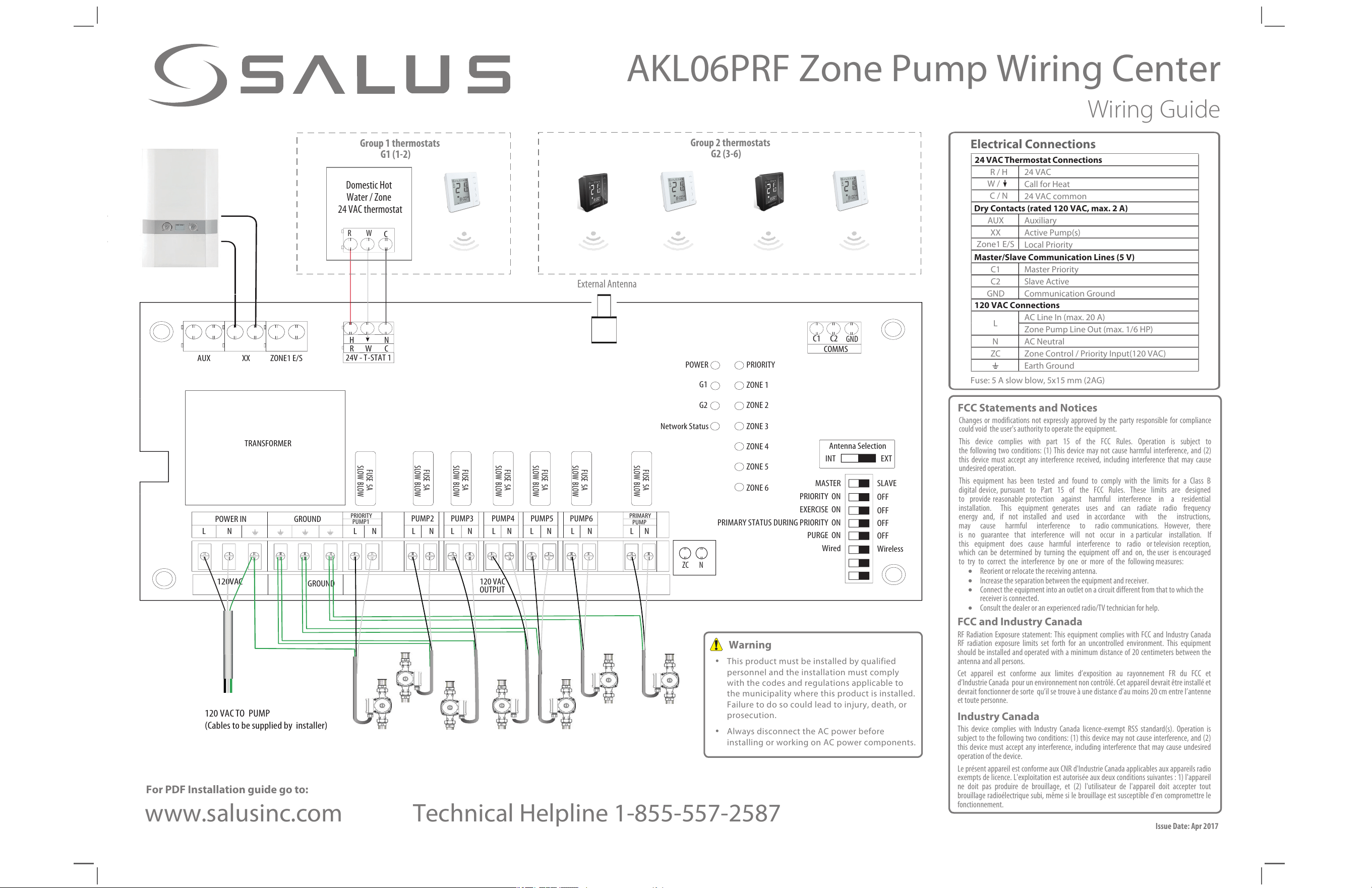
Domestic Hot
Water / Zone
24 VAC thermostat
R W
C
Group 1 thermostats
G1 (1-2)
Group 2 thermostats
G2 (3-6)
24 VAC Thermostat Connections
R / H 24 VAC
W /
Call for Heat
C / N
24 VAC common
Dry Contacts (rated 120 VAC, max. 2 A)
AUX Auxiliary
XX Active Pump(s)
Zone1 E/S
Local Priority
Master/Slave Communication Lines (5 V)
C1 Master Priority
C2 Slave Active
GND Communication Ground
120 VAC Connections
L
AC Line In (max. 20 A)
Zone Pump Line Out (max. 1/6 HP)
N AC Neutral
ZC
Zone Control
/
Priority Input(120 VAC)
Earth Ground
Fuse: 5 A slow blow, 5x15mm (2AG)
Electrical Connections
",-13';POF1VNQ8JSJOH$FOUFS
Installation Guide
1
2
3
DIP Switch
%FGJOJUJPO
."45&3
0''
0/
;POFJT
QVNQ[POF
&YFSDJTF0''
GPSBMMQVNQT
1SJNBSZ1VNQ0''
EVSJOH1SJPSJUZ
;POF0''
BUFOEPG1SJPSJUZ
8JSFMFTTUIFSNPTUBU
GPS;POF
."45&34-"7&
13*03*5:
&9&3$*4&
13*."3:45"564
%63*/(13*03*5:
163(&
8JSFE8JSFMFTT
;POFJT
1SJPSJUZ[POF
&YFSDJTF0/
GPSBMMQVNQT
1SJNBSZ1VNQ0/
EVSJOH1SJPSJUZ
;POF0''NJO
BGUFSFOEPG1SJPSJUZ
8JSFEUIFSNPTUBU
GPS;POF
8JSF UIF EFWJDF UP UIF "$ QPXFS
TVQQMZ BOE [POF QVNQT VTJOH XJSJOH
BQQSPQSJBUF GPS 7"$ $POOFDU
PUIFSUFSNJOBMTBTBQQSPQSJBUFUPPUIFS
EFWJDFTVTJOHQSPQFSXJSJOH#FTVSFUP
UISFBE XJSJOH UISPVHI UIF LOPDL PVUT
BOE VTF DBCMF DMBNQT UP GBTUFO UIF
XJSJOHUPUIFEFWJDF
A. Disconnect power
B. RFNPWF UIF QSPUFDUJWe
cover from the External
Antenna connector on the
top edge of the board.
C. Pass the antenna cable
through the antenna knock
out (and cable clamp) on
the top of the housing and
screw the cable onto the
connector.
D. Secure the cable using a
cable clamp.
E. Change the Antenna
Selection switch from INT to
EXT.
F. Reconnect power
5IF EFWJDF XJMM OPX VTF UIF FYUFSOBM BOUFOOB GPS
XJSFMFTT DPNNVOJDBUJPO
NOTE: 'PS SFHVMBUPSZ DPNQMJBODF POMZ UIF 4BMVT
"3'" BOUFOOB TPME TFQBSBUFMZ DBO CF VTFE XJUI
UIis EFWJDF
8
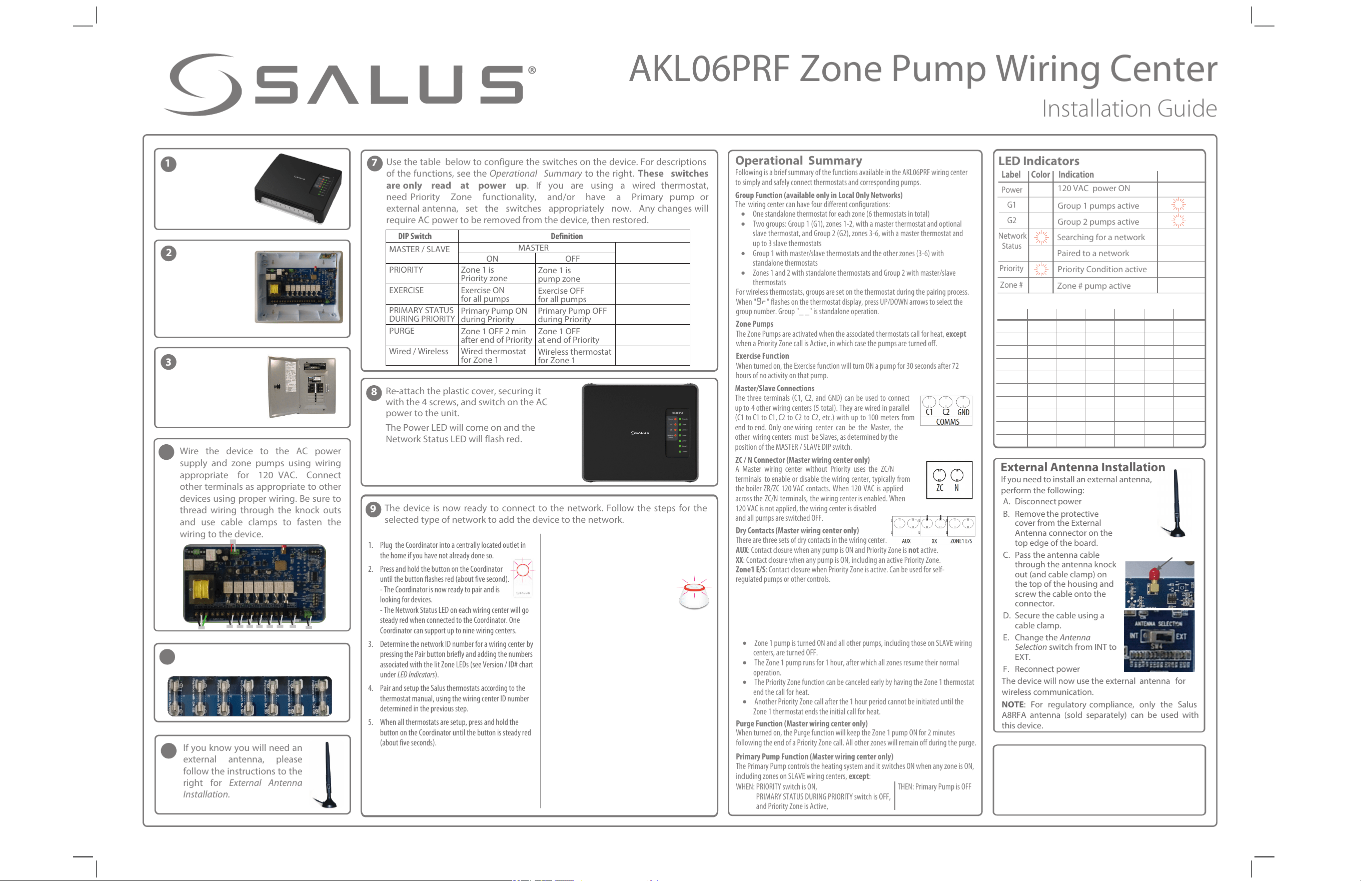
3FBUUBDIUIFQMBTUJDDPWFSTFDVSJOHJU
XJUIUIFTDSFXTBOETXJUDIPOUIF"$
QPXFSUPUIFVOJU
5IF1PXFS-&%XJMMDPNFPOBOEUIF
/FUXPSL4UBUVT-&%XJMMGMBTISFE
LED Indicators
Label Color Indication
1PXFS
/FUXPSL
4UBUVT
1SJPSJUZ
(
(
;POF
7"$QPXFS ON
(SPVQQVNQTBDUJWF
(SPVQQVNQTBDUJWF
4
FBSDIJOHGPSBOFUXPSL
1BJSFEUPBOFUXPSL
1SJPSJUZ$POEJUJPOBDUJWF
;POFQVNQBDUJWF
• One standalone thermostat for each zone (6 thermostats in total)
• Two groups: Group 1 (G1), zones 1-2, with a master thermostat and optional
slave thermostat, and Group 2 (G2), zones 3-6, with a master thermostat and
up to 3 slave thermostats
• Group 1 with master/slave thermostats and the other zones (3-6) with
standalone thermostats
• Zones 1 and 2 with standalone thermostats and Group 2 with master/slave
thermostats
For wireless thermostats, groups are set on the thermostat during the pairing process.
When "hs" flashes on the thermostat display, press UP/DOWN arrows to select the
group number. Group "_ _" is standalone operation.
Zone Pumps
The Zone Pumps are activated when the associated thermostats call for heat, except
when a Priority Zone call is Active, in which case the pumps are turned off.
Exercise Function
When turned on, the Exercise function will turn ON a pump for 30 seconds after 72
hours of no activity on that pump.
• Zone 1 pump is turned ON and all other pumps, including those on SLAVE wiring
centers, are turned OFF.
• The Zone 1 pump runs for 1 hour, after which all zones resume their normal
operation.
• The Priority Zone function can be canceled early by having the Zone 1 thermostat
end the call for heat.
• Another Priority Zone call after the 1 hour period cannot be initiated until the
Zone 1 thermostat ends the initial call for heat.
1VSHF'VODUJPO.BTUFSXJSJOHDFOUFSPOMZ
When turned on, the Purge function will keep the Zone 1 pump ON for 2 minutes
following the end of a Priority Zone call. All other zones will remain off during the purge.
1SJNBSZ1VNQ'VODUJPO.BTUFSXJSJOHDFOUFSPOMZ
The Primary Pump controls the heating system and it switches ON when any zone is ON,
including zones on SLAVE wiring centers, FYDFQU:
WHEN: PRIORITY switch is ON, THEN: Primary Pump is OFF
PRIMARY STATUS DURING PRIORITY switch is OFF,
and Priority Zone is Active,
Operational Summary
Following is a brief summary of the functions available in the AKL06PRF wiring center
to simply and safely connect thermostats and corresponding pumps.
(SPVQ'VODUJPOBWBJMBCMFPOMZJO-PDBM0OMZ/FUXPSLT
The wiring center can have four different configurations:
%SZ$POUBDUT.BT
UFSXJSJOHDFOUFSPOMZ
There are three sets of dry contacts in the wiring center.
"69: Contact closure when any pump is ON and Priority Zone is OPU active.
99: Contact closure when any pump is ON, including an active Priority Zone.
;POF&4: Contact closure when Priority Zone is active. Can be used for self-
regulated pumps or other controls.
.BTUFS4MBWF$POOFDUJPOT
The three terminals (C1, C2, and GND) can be used to connect
up to 4 other wiring centers (5 total). They are wired in parallel
(C1 to C1 to C1, C2 to C2 to C2, etc.) with up to 100 meters from
end to end. Only one wiring center can be the Master, the
other wiring centers must be Slaves, as determined by the
position of the MASTER / SLAVE DIP switch.
;$/$POOFDUPS.BTUFSXJSJOHDFOUFSPOMZ
A Master wiring center without Priority uses the ZC/N
terminals to enable or disable the wiring center, typically from
the boiler ZR/ZC 120 VAC contacts. When 120 VAC is applied
across the ZC/N terminals, the wiring center is enabled. When
120 VAC is not applied, the wiring center is disabled
and all pumps are switched OFF.
*GZPVLOPXZPVXJMMOFFEBO
FYUFSOBM BOUFOOB QMFBTF
GPMMPXUIFJOTUSVDUJPOTUPUIF
SJHIU GPS External Antenna
Installation.
6TF UIF UBCMF CFMPX UP DPOGJHVSF UIF TXJUDIFT PO UIF EFWJDF 'PS EFTDSJQUJPOT
PG tIF GVODUJPOT TFF UIF Operational Summary UP UIF SJHIU These switches
are only read at power up *G ZPV BSF VTJOH B XJSFE UIFSNPTUBU
OFFE 1SJPSJUZ ;POF GVODUJPOBMJUZ BOEPS IBWF B 1SJNBSZ QVNQ PS
FYUFSOBM BOUFOOB TFU UIF TXJUDIFT BQQSPQSJBUFMZ OPX "OZ DIBOHFT XJMM
SFRVJSF "$ QPXFS
UP CF SFNPWFE GSPN UIFEFWJDF UIFO SFTUPSFE
7
9
5IF EFWJDF JT OPX SFBEZ UP DPOOFDU UP UIF OFUXPSL 'PMMPX UIF TUFQT GPS UIF
TFMFDUFEUZQFPGOFUXPSLUPBEEUIFEFWJDFUPUIFOFUXPSL
1. Plug the Coordinator into a centrally located outlet in
the home if you have not already done so.
2. Press and hold the button on the Coordinator
until the button flashes red (about five second).
- The Coordinator is now ready to pair and is
looking for devices.
- The Network Status LED on each wiring center will go
steady red when connected to the Coordinator. One
Coordinator can support up to nine wiring centers.
3. Determine the network ID number for a wiring center by
pressing the Pair button briefly and adding the numbers
associated with the lit Zone LEDs (see Version / ID# chart
under LED Indicators).
4. Pair and setup the Salus thermostats according to the
thermostat manual, using the wiring center ID number
determined in the previous step.
5. When all thermostats are setup, press and hold the
button on the Coordinator until the button is steady red
(about five seconds).
External Antenna Installation
*G ZPV OFFE UP JOTUBMM BO FYUFSOBM aOUFOOB
QFSGPSN UIF GPMMPXJOH
4
3FNPWFUIF
DPWFSCZ
VOTDSFXJOHUIF
TDSFXTBUUIF
DPSOFST
"UUBDIUIFCBDL
PGUIFEFWJDFUP
UIFXBMMBU
BTVJUBCMF
MPDBUJPOVTJOH
UIFJODMVEFE
IBSEXBSF
%JTDPOOFDUUIF
"$QPXFSUPUIF
"$XJSJOHGPS
UIFEFWJDF
.BLF TVSF FBDI GVTF JT " TMPXCMPX
BOEJOTFSUFEDPSSFDUMZ
Antenna
protective cover
t
t
t
t
t
t
t
t
t
*(/03&%;POF
JTQVNQ[POF
4BNFBT.BTUFS
*(/03&%1SJNBSZ
1VNQBMXBZT0''
*(/03&%
/P1SJPSJUZ
4BNFBT.BTUFS
4-"7&
1. Setup the Basic Gateway as instructed and associate the
gateway with the wyse.ly service account.
2. Go to the "EE/FX&RVJQNFOU page on the wyse.ly
app and press "Scan for equipment".
- The gateway ring will flash red indicating
that it is looking for devices.
3. Use the wyse.ly app to add the wiring centers to your
wyse.ly network.
- The Network Status LED on each wiring center will go
steady red when connected to the Basic Gateway.
4. Use the wyse.ly app to add the Salus thermostats to
your network and associate them with the desired
wiring center and zone.
5. When all devices are setup, exit the "EE /FX
&RVJQNFOU function on the wyse.ly app.
- The gateway ring will turn steady blue to indicate
normal operating mode.
-PDBM0OMZ/FUXPSLVTJOH;JH#FF$PPSEJOBUPS
*OUFSOFU$POOFDUFE/FUXPSLVTJOH#BTJD(BUFXBZ
$IFDLJOH 4ZTUFN $POGJHVSBUJPO BOE $PNNVOJDBUJPO
$PPSEJOBUPSUP8JSJOH$FOUFST
Press and hold the coordinator button for one second. All
devices connected to the coordinator will flash. To stop
checking, press and hold the coordinator button again for
one second.
$IFDLJOH 4ZTUFN $POGJHVSBUJPO BOE $PNNVOJDBUJPO
(BUFXBZUP8JSJOH$FOUFS
Go to the Wyse.ly App and press the Identify button for the
desired wiring center. The desired wiring center will start
flashing the G1 and G2 LEDs. To stop the identify process,
press the Identify button on the App again.
5
6
Version /
WCID #
t
t
Value = sum of zone numbers
;POF;POF;POF;POF;POF;POF
t
t
t t
t
t
t
t
t
t
t
t
t
t
t
t
t
t
Factory Default Reset
To restore the device to Factory Default settings, press and hold the Pair
button until both G1 and G2 LEDs go off after becoming steady red.
/PUF: Restoring to Factory Default will remove the wiring center from
the network and delete all associated devices.
IDENTIFY
Indicators
1SJPSJUZ;POF'VODUJPO.BTUFSXJSJOHDFOUFSPOMZ
The Priority Zone function is usually used to give domestic hot water (DHW) priority for
the boiler output. Activating this function will change the behavior of Zone 1 on the
MASTER wiring center. When Priority is ON and the Zone 1 thermostat calls for heat,
the following occurs as part of an active Priority Zone: