Braeburn Systems LLC • 2215 Cornell Avenue • Montgomery, IL 60538
©2023 Braeburn Systems LLC • All Rights Reserved.
AKL04P-100-02
Technical Support 1-888-387-2587 www.salusinc.com
LED Indication
Label
Color
Function
Power
Red
120VAC Power ON
Priority
Green
Priority Mode Active
Zone
Green
Zone # X Active
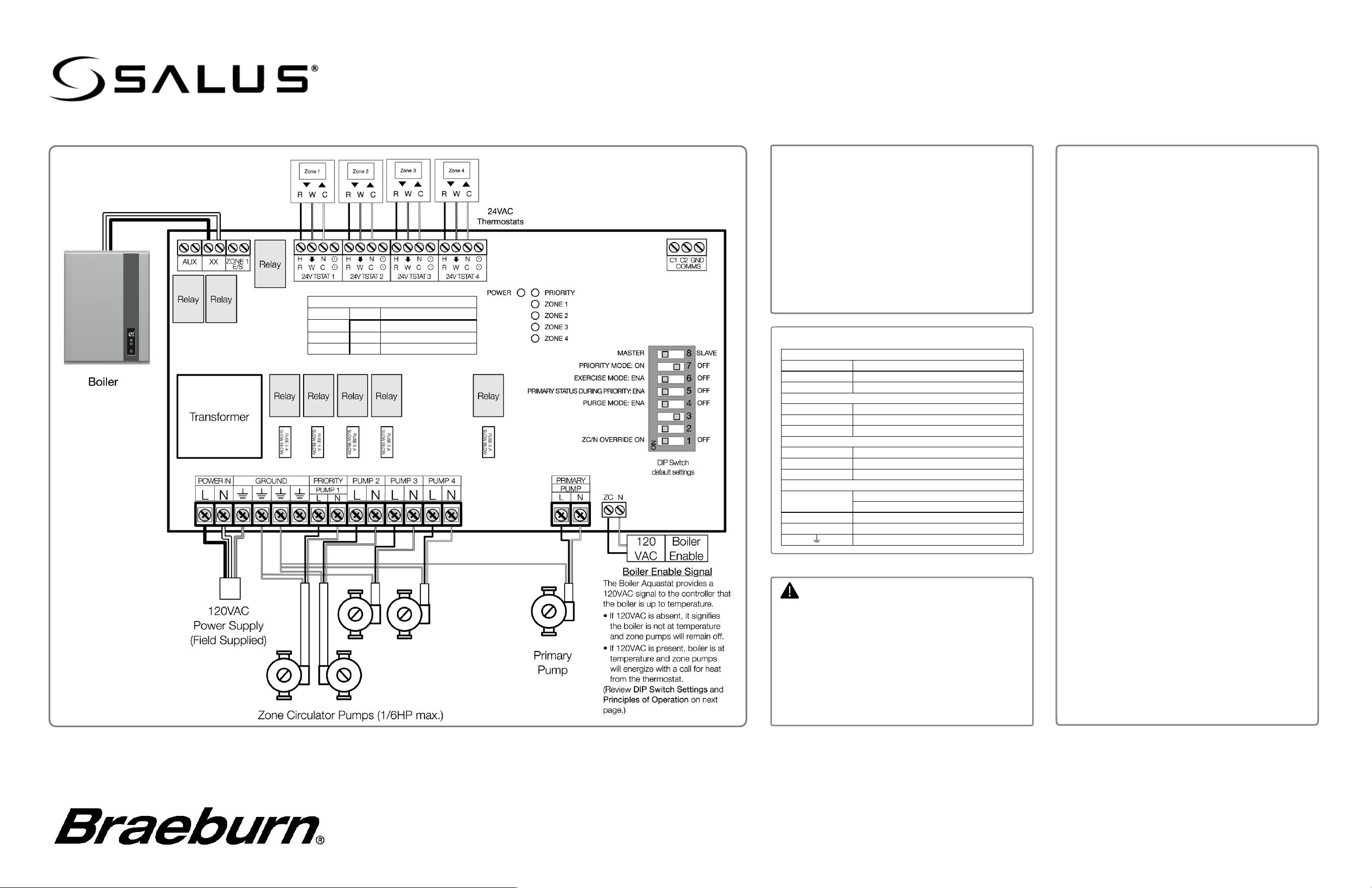
Electrical Connections
24VAC Thermostat Connections
R
24VAC – Hot
W
Call for Heat
C
24VAC – Common
Dry Contacts (rated 2A @ 120VAC)
AUX
Auxiliary
XX
Boiler Control
Zone 1 E/S
Local Priority
Master/Slave Communications
C1
Master – Priority Active
C2
Slave – Primary Active
GND
Communication Ground
120VAC Connections
L
AC Line In (max 20A @ 120VAC)
Zone Pump Line Out (max 1/6HP)
N
AC Neutral
ZC
Zone Control/Priority Input (120VAC)
Earth Ground
Warning
• This product must be installed by qualified
personnel and the installation must comply
with the codes and regulations applicable to
the municipality where this product is
installed. Failure to do so could lead to injury,
death, or prosecution.
• Always disconnect the AC power before
installing or working on AC power
components.
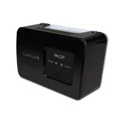
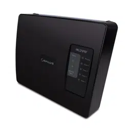
The AKL04P Pump Controller provides zone
control for up to 4 circulators as well as boiler and
Primary pump outputs.
• Zone thermostats are set independently and
will provide a call for heat to energize the zone
circulator.
• Zone 1 may be assigned to domestic hot
water control with priority over zone outputs.
• Up to 5 controllers may be daisy-chained fo
r
larger systems.
• LED indicators provide a visual indication of
control status.
AKL04P Pump Relay Controller
Wiring Guide
FCC and Industry Canada Statements
WARNING: Changes or modifications to this unit not expressly
approved by the party responsible for compliance could void the
user’s authority to operate the equipment.
This device complies with Part 15 of the FCC Rules. Operation
is subject to the following two conditions: (1) this device may not
cause harmful interference, and (2) this device must accept any
interference received, including interference that may cause
undesired operation.
NOTE: This equipment has been tested and found to comply
with the limits for a Class B digital device, pursuant to Part 15 of
the FCC Rules. These limits are designed to provide reasonable
protection against harmful interference in a residential
installation. This equipment generates, uses and can radiate
radio frequency energy, and if not installed and used in
accordance with the instructions, may cause harmful
interference to radio communications. However, there is no
guarantee that interference will not occur in a particular
installation. If this equipment does cause harmful interference to
radio or television reception, which can be determined by turning
the equipment off and on, the user is encouraged to try to
correct the interference by one or more of the following
measures:
• Reorient or relocate the receiving antenna.
• Increase the separation between the equipment and
receiver.
• Connect the equipment into an outlet on a circuit different
from that to which the receiver is connected.
• Consult the dealer or an experienced radio/TV technician
for help.
FCC
AND INDUSTRY CANADA
RF Radiation Exposure statement: !This equipment complies
with FCC and Industry Canada RF radiation exposure limits set
forth for an uncontrolled environment. This equipment should be
installed and operated with a minimum distance of 20
centimeters between the antenna and all persons.
I
NDUSTRY CANADA
This device complies with Industry Canada licence-exempt RSS
standard(s). Operation is subject to the following two conditions:
(1
) this device may not cause interference, and (2) this device
must accept any interference, including interference that may
cause undesired operation of the device.
Le présent appareil est conforme aux CNR d'Industrie Canada
applicables aux appareils radio exempts de licence.
L'exploitation est autorisée aux deux conditions suivantes : (1)
l'appareil ne doit pas produire de brouillage, et (2) l'utilisateur de
l'appareil doit accepter tout brouillage radioélectrique subi,
même si le brouillage est susceptible d'en compromettre le
fonctionnement.
!
Configuring the Pump Relay Controller
The Zone Pump controller is used to control circulator pumps based on the
corresponding temperature of one or more wireless zone thermostats.
The Zone 1 output can be designated as a domestic hot water Priority Pump
(see below). There is a designated output for a Primary hot water pump.
The AUX, XX, and Zone 1 E/S dry-contact outputs may be used for a variety
of control functions (see below).
1. You can add one pump for each zone (4 in total), one primary pump, and
one priority pump.
2. You can use 2, 3, or 4-wire thermostats that are compatible with your
system.
3. Make sure that the thermostats are all 24VAC.
Principles of Operation
Primary Pump
The primary pump controls the main heating loop and will be switched on
when any zone is on. Exception: If the DIP Switch for Priority is ON, and the
DIP Switch for Primary status during priority OFF , then the primary pump will
be off during a priority call.
Priority Pump
The priority pump, if enabled, is for controlling the domestic hot water.
On the unit designated as the Master controller, when the Zone 1 thermostat
calls for heat, the Priority pump will turn ON and for the first hour, all other
zones will be held OFF.
After 1 hour, all the zones will resume to their normal function. To enable the
Priority pump there needs to be a Zone 1 thermostat connected to the
domestic hot water control.
Zone Pumps
The Zone pumps will be activated when the thermostats are calling for heat,
except when the priority zone is activated.
Auxiliary Outputs
There are 3 volt-free auxiliary outputs:
AUX:
Will turn ON when any pump is ON, and the Priority pump is OFF
XX:
Will turn ON when any zone is ON, including the Priority zone
Zone 1 E/S:
Will turn ON when there is a priority call for DHW, this is used
to override the boiler weather compensation.
Communication connections
Terminals (C1,C2, ) are used whenever Slave controllers are used with a
Master controller.
Up to 4 slave pump controllers may be connected, C1 to C1, C2 to C2, to
.
The master wiring center must have the DIP switch set to Master and the
slave controllers must be set to Slave.
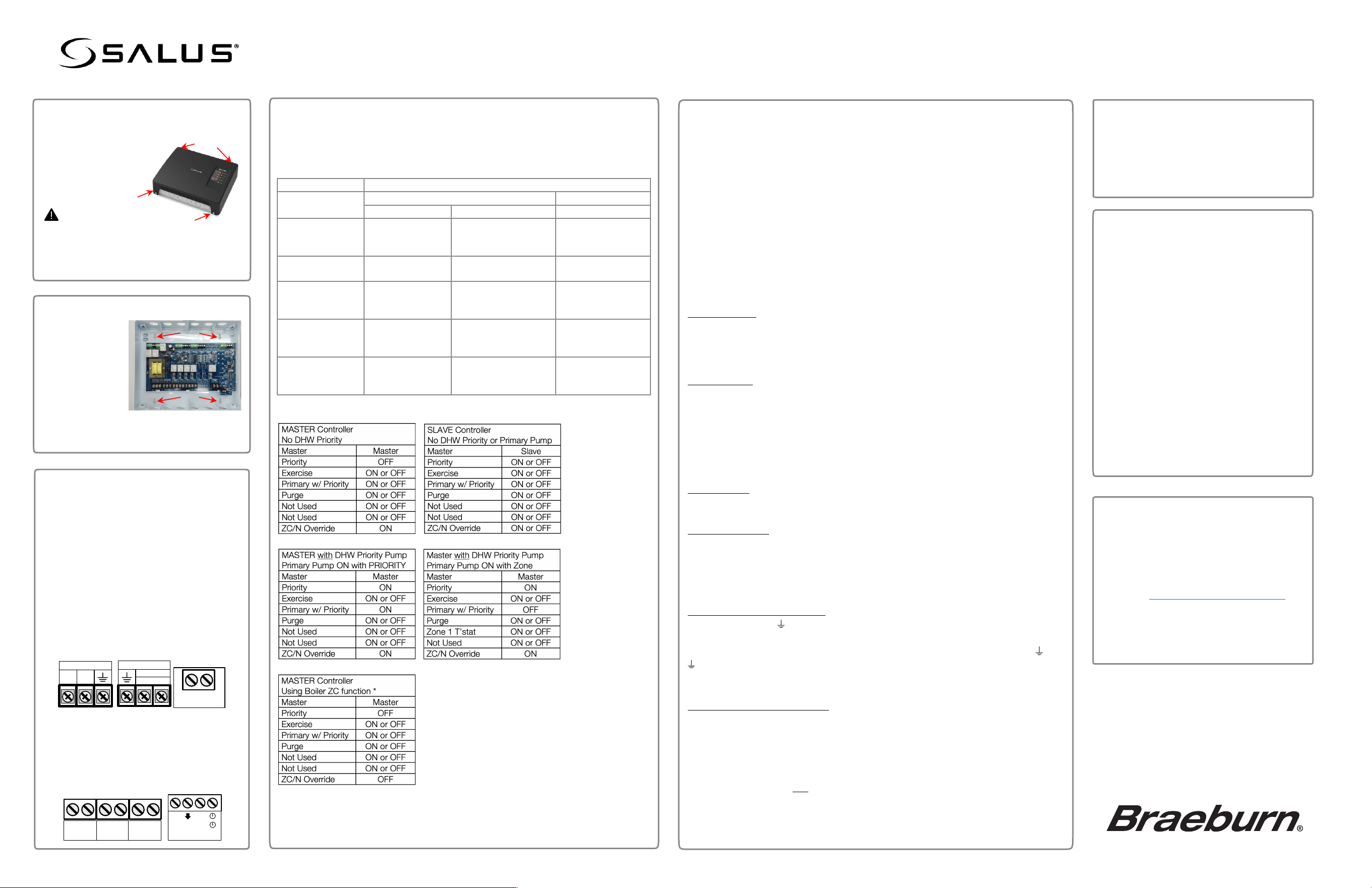
ZC/N Override (Boiler Enable)
When Master switch is ON and Priority Switch is OFF, the ZC/N
connector may be used to enable or disable the unit based upon the
output from the boiler ZR/ZC 120V contact.
• When 120VAC is applied across ZC/N terminals, the controller outputs
will be enabled.
• When 120VAC is not present, the controller will be disabled, and all
pumps will be switched off.
AKL04P Pump Relay Controller
Installation
Guide
"
Remove the cover:
Loosen the 4 screws on each corner and
set aside.
Warning
Disconnect power from the controller
before removing the cover.
More than one power source may be
present.
#
Mount the controller.
$
DIP Switch Settings:
Refer to tables below for DIP Switch configuration. For descriptions of the
functions, see Principles of Operation below. The controller reads the DIP
switches when power is removed from the device for approximately 10
seconds, then restored.
DIP Switch
Definition
MASTER / SLAVE
Master
Slave
ON
OFF
PRIORITY
Zone1 is Priority
Zone
Zone1 is Pump Zone
Ignored
Zone1 is pump
zone
EXERCISE
Exercise ON for
all pumps
Exercise OFF for all
pumps
Same as Master
PRIMARY
STATUS DURING
PRIORITY
Primary Pump
ON during
Priority
Primary Pump OFF
during Priority
Ignored
PURGE
Zone1 ON 2 min
after end of
Priority
Zone1 OFF at the
end of Priority
Ignored
ZC/N Override
Boiler Enable
Ignored
Pumps do not
energize without Boiler
Enable.
Ignored
Set the DIP Switches for the desired operation.
NOTE:
Power must be reset for DIP switch changes to take effect.
%
Wire the Controller
Use the knockouts on the bottom of the
controller for high voltage cables and
those on the top for low voltage cables.
Insert the cables through the knockouts
and use cable clamps to secure the
wiring to the device.
• Wire the AC power to POWER IN.
• Connect the pumps to the
appropriate zone output.
• Wire the boiler override signal to the
ZC/N terminals (if needed).
• Connect devices to be controlled to
the AUX, XX and Zone 1/ES outputs
(as required).
• Connect the 2, 3, or 4 wire zone
thermostats to the associated zone
input.
L N
POWER IN
L N
PRIORITY
PUMP 1
ZC N
AUX XX
E/S
ZONE 1
H N
R W C
24V TSTAT 1
&
Attach Cover and apply power.
Re-attach the plastic cover.
Secure it with the 4 screws.
Apply AC power to the unit.
The Power LED will come on.
* With Boiler ZC/R output connected to ZC/N
terminals and:
• PRIORITY is OFF
• ZC/N OVERRIDE is OFF
With:
• 120VAC Present, Outputs are enabled.
• 120VAC not present, Outputs are disabled.
Zone control will function normally if:
• PRIORITY is set to ON.
• ZC/N OVERRIDE is set to ON.
'
Troubleshooting
If the pumps do not energize:
1. Confirm that there is power to the
pump controller.
2. Confirm the Zone LED ON.
3. Confirm that the thermostat is
connected to the correct Zone.
4. Verify that the thermostat is calling for
heat.
5. Confirm that the 5A fuse is installed
and not blown.
6. If ZC/N switch is set to OFF:
a. Confirm that the boiler is on and
at temperature.
b. Confirm that there is 120VAC on
the ZC and N terminals.
Attach the base
to a flat surface
in a suitable
indoor location.
Four mounting holes are provided that
will accept #8 pan-head screws.
Limited Warranty
When installed by a professional contractor, this
product is backed by a 5 year limited warranty.
Limitations apply. For limitations, terms and
conditions, you may obtain a full copy of this
warranty:
• Visit us
online: www.braeburnonline.com/warranty
• Phone us: 866.268.5599
• Write us:
Braeburn Systems LLC
2215 Cornell Avenue
Montgomery, IL 60538