OPERATOR’S MANUAL
For technical assistance or the Water Maze Dealer nearest you,
call (800) 535-0941 or (360) 833-2333 or consult our web page at www.wmaze.com
8.913-964.0 - J07/10/25
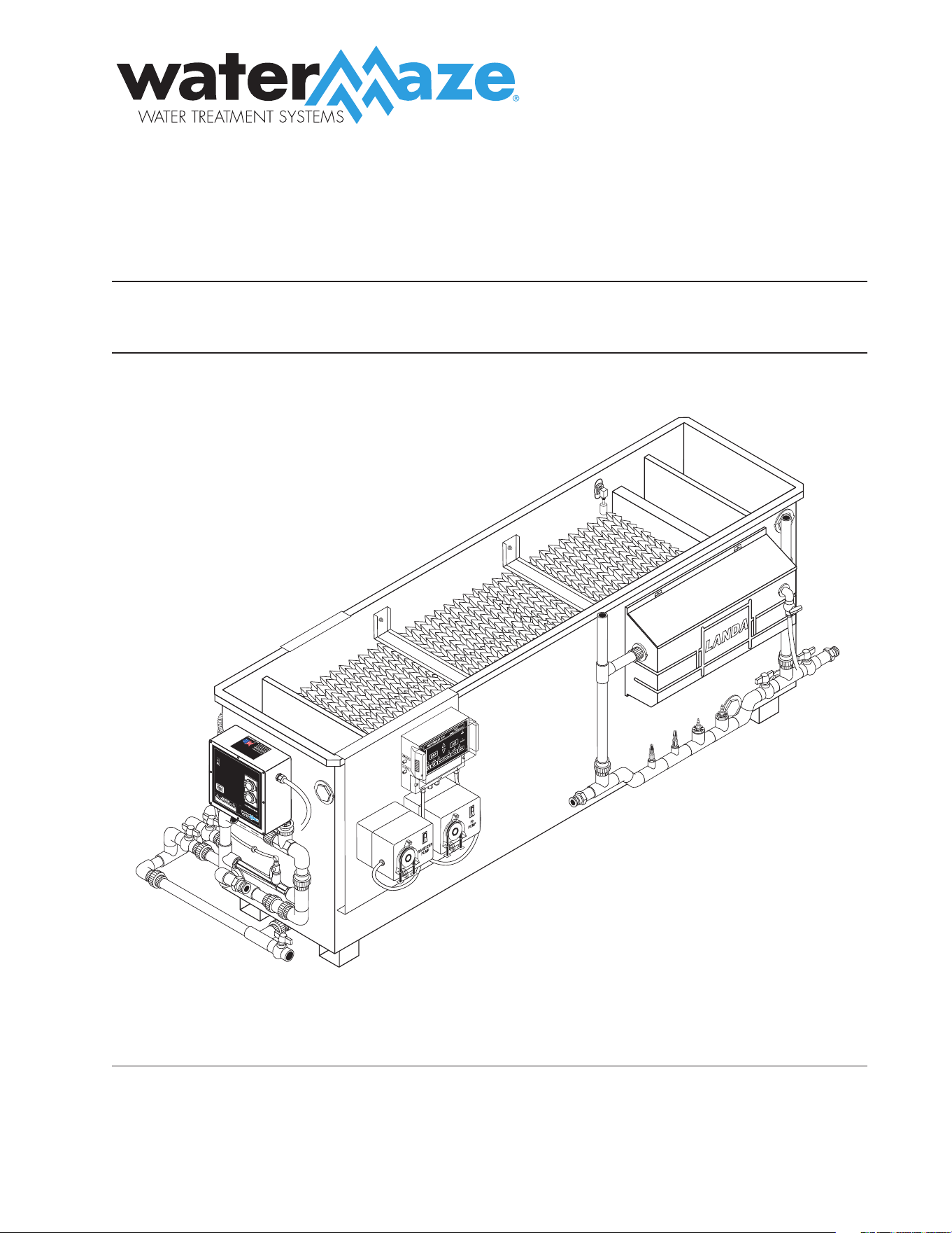
■ ALPHA-1500
ALPHA

CONTENTS
2
ALPHA • 1500 • #8.913-964.0-J
Introduction ..................................................................................................................................................................................4
Owner/User Responsibility ......................................................................................................................................................4
Unpacking ......................................................................................................................................................................................4
Safety Instructions ..................................................................................................................................................................4-5
General Operating Techniques ........................................................................................................................................ 5, 10
Installation ............................................................................................................................................................................. 6 -10
Start-Up..................................................................................................................................................................................11-12
Operation .................................................................................................................................................................................... 12
General Maintenance and Service ..................................................................................................................................... 12
Chemical Maintenance .......................................................................................................................................................... 13
Owner Chemical Maintenance Program.......................................................................................................................... 13
Daily Chemical Maintenance ............................................................................................................................................... 14
Optional ORP/pH Controller ...........................................................................................................................................14-16
Submersible Sump Pumps .................................................................................................................................................... 17
Pump Safety Information ...................................................................................................................................................... 17
Pre-installation/Sump Pit Info ............................................................................................................................................. 18
Pump Installation ..................................................................................................................................................................... 18
Pump Operation ....................................................................................................................................................................... 18
Pump Maintenance ................................................................................................................................................................. 18
Peristaltic Metering Pump ..................................................................................................................................................... 19
Ozone Generator Operation ................................................................................................................................................. 20
Ozone Generator Maintenance .....................................................................................................................................20-21
Ozone Generator Testing ....................................................................................................................................................... 22
Ozone Generator Breakdown .............................................................................................................................................. 23
Ozone Generator Parts List ................................................................................................................................................... 24
Inlet Side - Alpha-1500 Exploded View and Parts List ...........................................................................................25-26
Right Side - Alpha-1500 Exploded View and Parts List .........................................................................................27-28
Discharge Side, Exploded View and Parts List ............................................................................................................... 29
Top View - Alpha 1500 ............................................................................................................................................................ 30
Troubleshooting .................................................................................................................................................................31-32
Preventative Maintenance .................................................................................................................................................... 33
Specications ............................................................................................................................................................................. 34

Model Number ______________________________
Serial Number ______________________________
Date of Purchase ____________________________
The model and serial numbers will be found on a decal attached to the
Alpha. You should record both serial number and date of purchase and
keep in a safe place for future reference.
CONTENTS
3
ALPHA • 1500 • #8.913-964.0-J
Warranty ...................................................................................................................................................................................... 36
Model #: 1.103-401.0
4
ALPHA SERIES OPERATOR’S MANUAL
ALPHA 1500 • #8.913-964.0-J
INTRODUCTION
Your owner’s manual has been prepared to provide you with
a simple and understandable guide for equipment opera-
tion and maintenance, based on the latest product informa-
tion available at the time of printing. To keep your machine
in top running condition, follow the specic maintenance
and troubleshooting procedures given in this manual. When
ordering parts please specify model and serial number.
This manual should be considered a permanent part of the
machine and should remain with the machine if resold.
Owner/User Responsibility:
The owner and/or user must have an understanding of the
manufacturer’s operating instructions and warnings before
using this WATER MAZE machine. Warning information
should be emphasized and understood. If the operator is
not uent in English, the manufacturer’s instructions and
warnings shall be read to and discussed with the operator
in the operator’s native language by the purchaser/owner,
making sure that the operator comprehends its contents.
The owner and/or user must study and maintain the manu-
facturers’ instructions for future reference.
NOTE: WATER MAZE, Inc. reserves the right to make changes
at anytime without incurring any obligations.
This manual should be considered a permanent part
of the machine and should remain with it if machine
is resold.
When ordering parts, please specify model and se-
rial number.
UNPACKING
1. Alpha module with cover
2. Two 1-1/2" (3.81 cm) ball valves for recycle system
3. 1-1/2" x 16' (3.81 cm x 4.89 m) recycle hose back
to pit
4. Ozone Generator
5. Operator’s Manual
6. Drain Valve Manifold
Note any damage to machine or components for claims
against the freight lines.
SAFETY INSTRUCTIONS
WARNING: To reduce the risk of
injury, read operating instructions
carefully before using.
1. Read the owner’s manual thor-
oughly. Failure to follow the
instructions could cause a mal-
function of the machine and
result in death, serious injury
and/or property damage.
DANGER: Wire the system for correct
voltage. See “Electrical” section of
this manual and motor nameplate.
DANGER: Follow the wiring instruc-
tions in this manual when connect-
ing the system to the power lines.
DANGER: All wiring must be per-
formed by a qualied electrician.
DANGER: Meet the National Electri-
cal Code and local codes for all wiring.
2. The installation of the machine must comply with local
and/or national codes.
DANGER: Ground system before connecting to the power
supply.
3. This machine, when installed, must be electrically
grounded in accordance with local and/or national
codes. Do not spray water near electrical components.
4. Never make adjustments on the machine while it is in
operation, except for those described in this manual.
WARNING
RISK OF EXPLOSION:
DO NOT USE WITH
FLAMMABLE LIQUIDS.
WARNING: Do not discharge concen-
trations of ammable or explosive
uids such as gasoline, fuel oil, kero-
sene, etc. into the Clarier. Do not
use in explosive atmospheres. Fail-
ure to follow this warning can pro-
duce an explosion resulting in per-
sonal injury and/or property dam-
age.
5. Do not discharge gasoline or other volatile hydro-
carbons into the Alpha. This could cause a gas vapor
build-up under the lid which could become an explosive
mixture.
READ OPERATOR’S
MANUAL THOROUGHLY
PRIOR TO USE.
WARNING
HAZARDOUS
VOLTAGE. CAN SHOCK,
BURN OR CAUSE
DEATH.
DANGER

ALPHA SERIES OPERATOR’S MANUAL
5
ALPHA 1500 • #8.913-964.0-J
WARNING: Wear protective eye-
wear, foot protection and protective
clothing.
6. Before servicing the
machine, refer to all the MSDS’s
on the material identied in the
waste stream. You must comply
with all warnings and wear all
protective clothing as stated on
the MSDS’s.
7. Protect from freezing and UV light.
8. Protect inlet and outlet hose from vehicle trac and
sharp objects.
9. Be certain couplers on hoses have been locked before
operating.
10. Before disconnecting hoses, turn machine o.
11. Inlet water temperature must not exceed 95°F/35°C.
12. When making repairs disconnect machine from electri-
cal source.
13. The best insurance against an accident is precaution
and knowledge of the equipment.
14. WATER MAZE is not liable for any modifications
or the use of components not purchased from
WATER MAZE.
15. The Alpha and its components will freeze, and must be
located in a heated enclosure in cold climates.
16. Running the system without water will damage the
pump and may void the warranty.
17. The Alpha should be installed and started up by an
authorized WATER MAZE dealer.
18. The Alpha and its components must be protected from
weather, i.e. wind, rain, direct sun, etc.
GENERAL OPERATING
TECHNIQUES
The only operator adjustment to the Alpha is the valve on
the inlet to the Alpha. The ow to the Alpha should be 25
GPM (94.63 L/M) or less. The recommended nominal ow
rate is 10-15 GPM (37.85 - 56.78 L/M).
INSTALLATION
These machines are designed for indoor use only.
Machines must be stored indoors when not in use.
Location
The Alpha must be installed on a level surface, preferably a
concrete pad near the wastewater collection sump. In cold
climates the Alpha will freeze and should be located in a
heated enclosure. The Alpha must be located in a heated
enclosure for at least 24 hours prior to start up.
WARNING
PROTECTIVE
EYE WEAR AND
CLOTHING MUST
BE WORN.
6
ALPHA SERIES OPERATOR’S MANUAL
ALPHA 1500 • #8.913-964.0-J
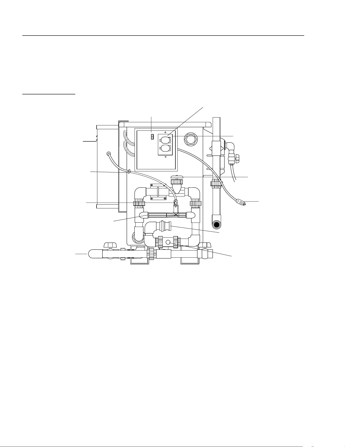
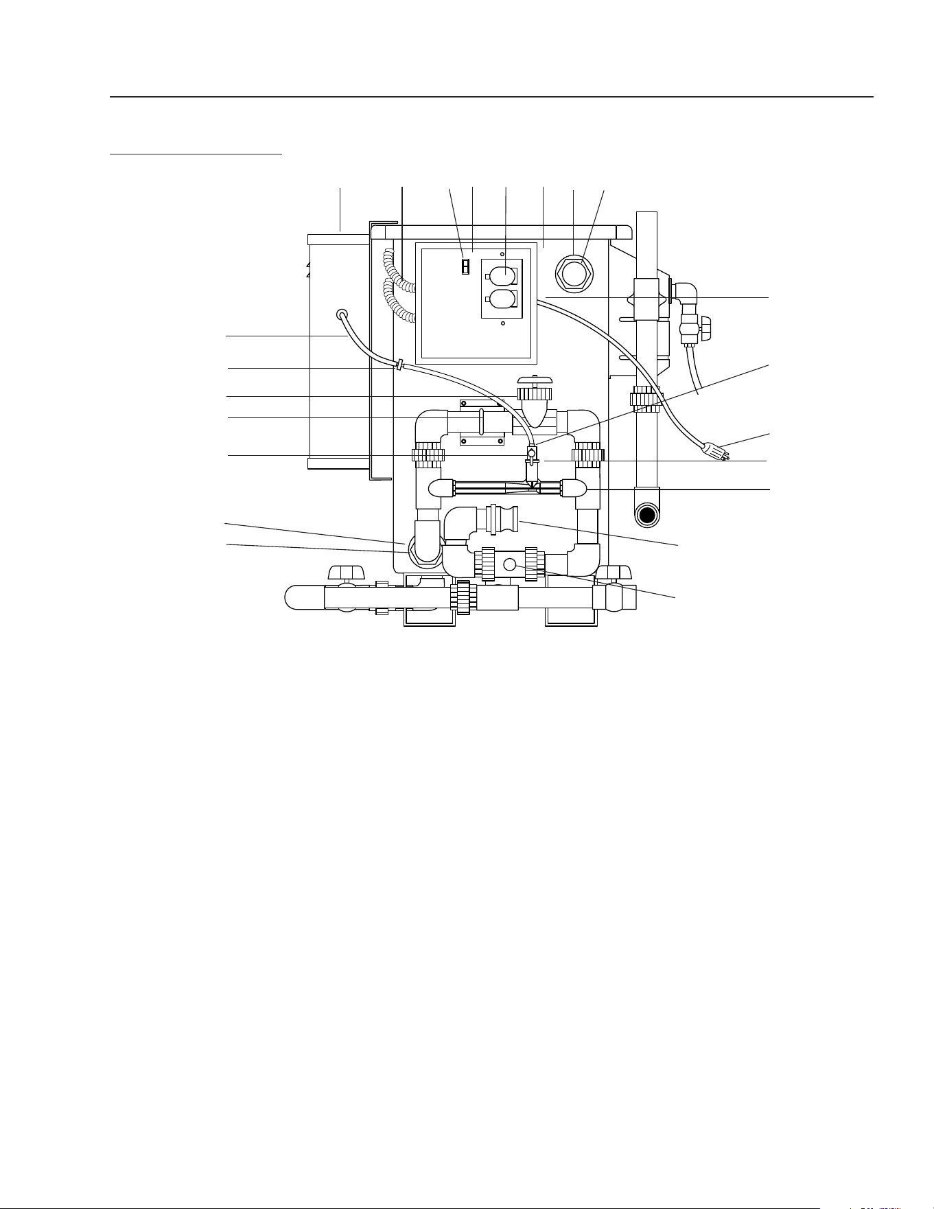
INSTALLATION
FRONT VIEW ALPHA-1500
(INLET END)
Control Panel
Figure 1
120V AC Power In
Flow Control Valve
Ozone Metering Valve
Ozone Injector
Check Valve
Ozone Check Valve
Ozone Generator
On/O Switch
Sump Pump Receptacle
Inlet Connection
Drain Manifold
ALPHA SERIES OPERATOR’S MANUAL
7
ALPHA 1500 • #8.913-964.0-J
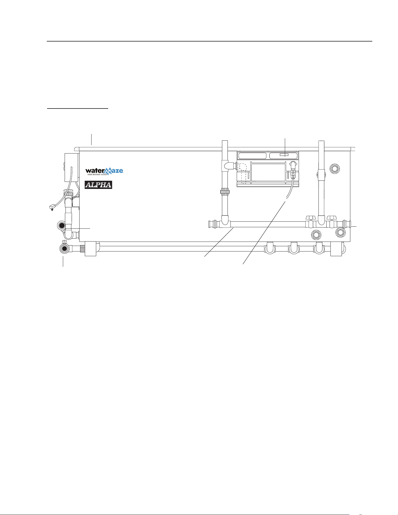
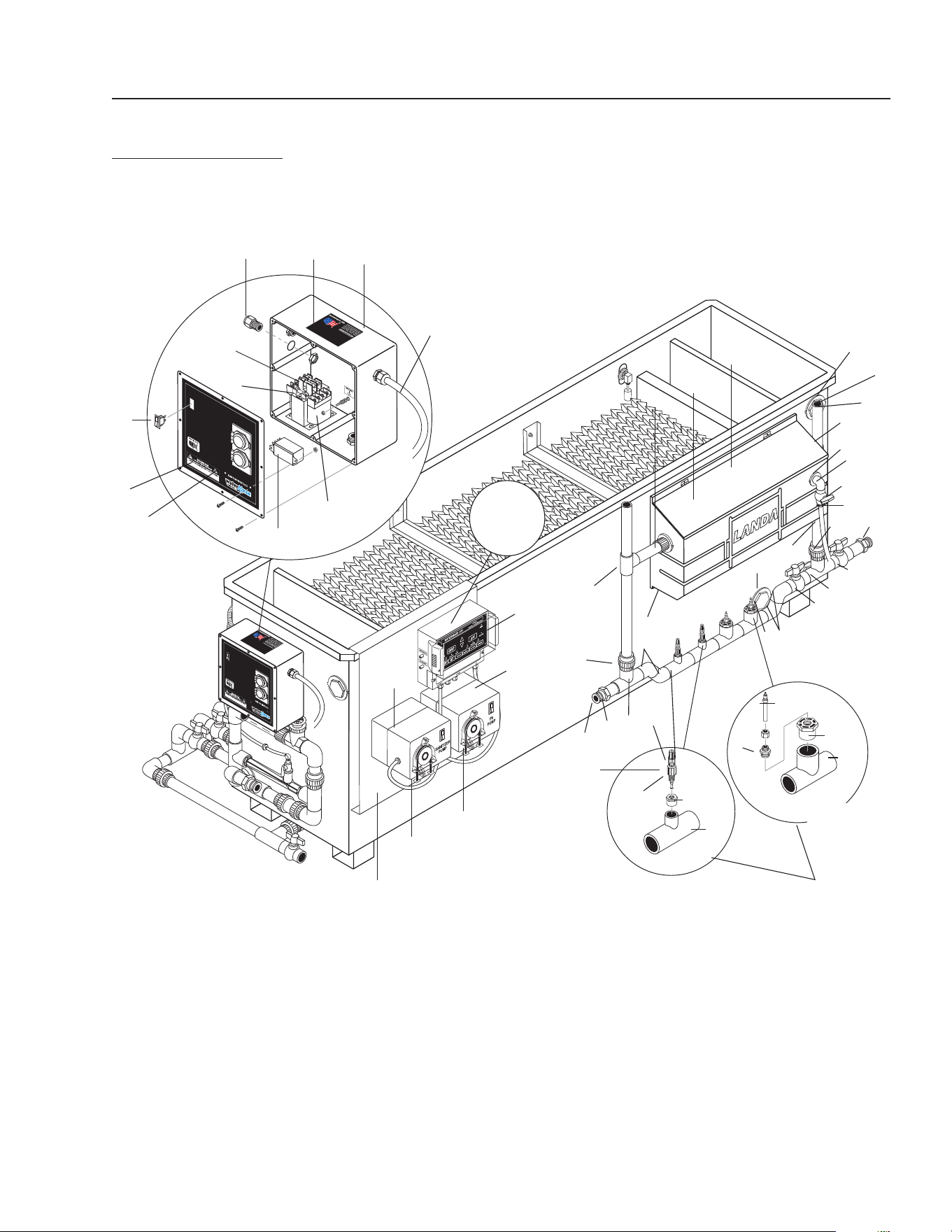
INSTALLATION
SIDE VIEW ALPHA-1500
Figure 2
Recycle Line
▲
Ozone Generator (Far Side)
Oil Skimmer Float Tank Assembly
Outlet
Oil Drain Line
Drain
Manifold
Inlet
Connection
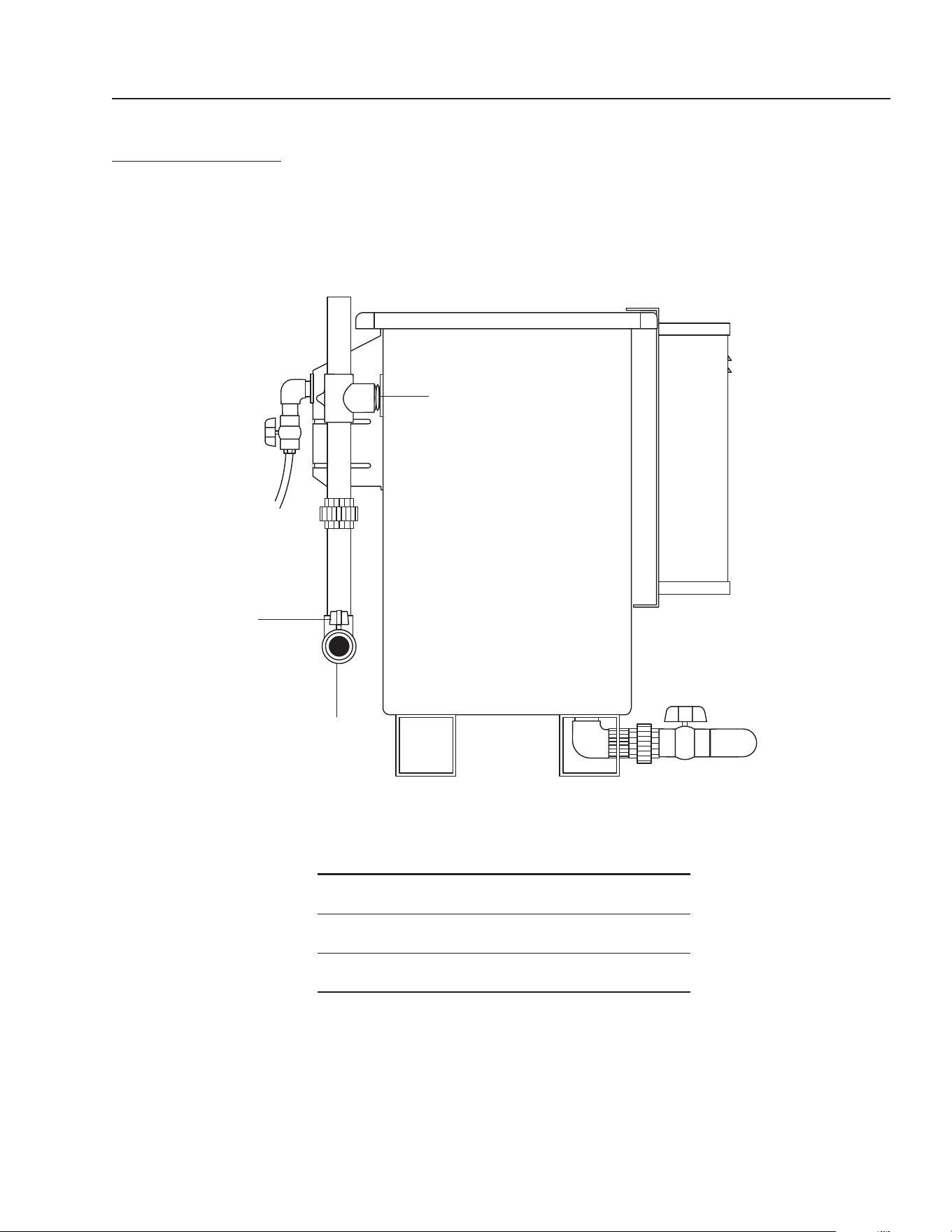
8
ALPHA SERIES OPERATOR’S MANUAL
ALPHA 1500 • #8.913-964.0-J
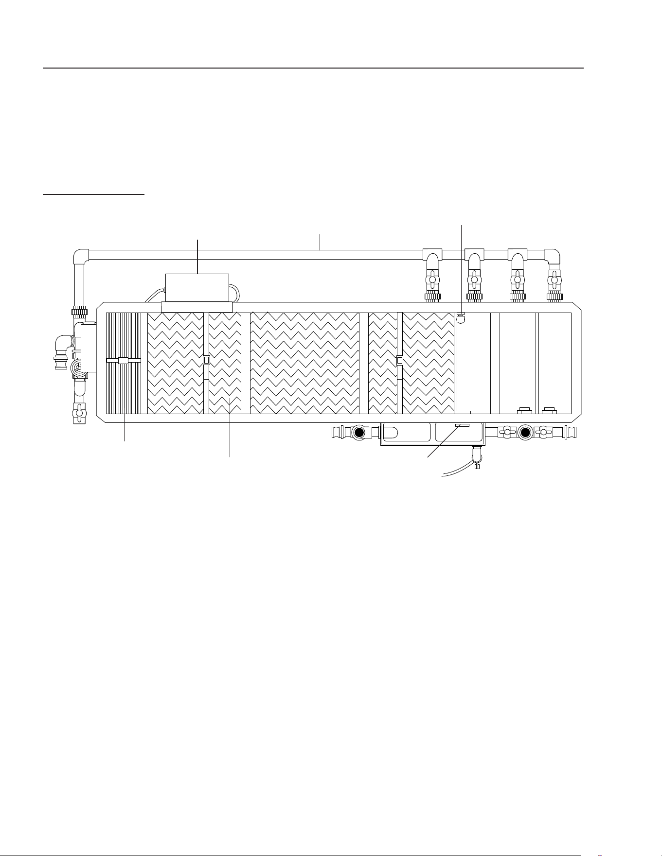
INSTALLATION
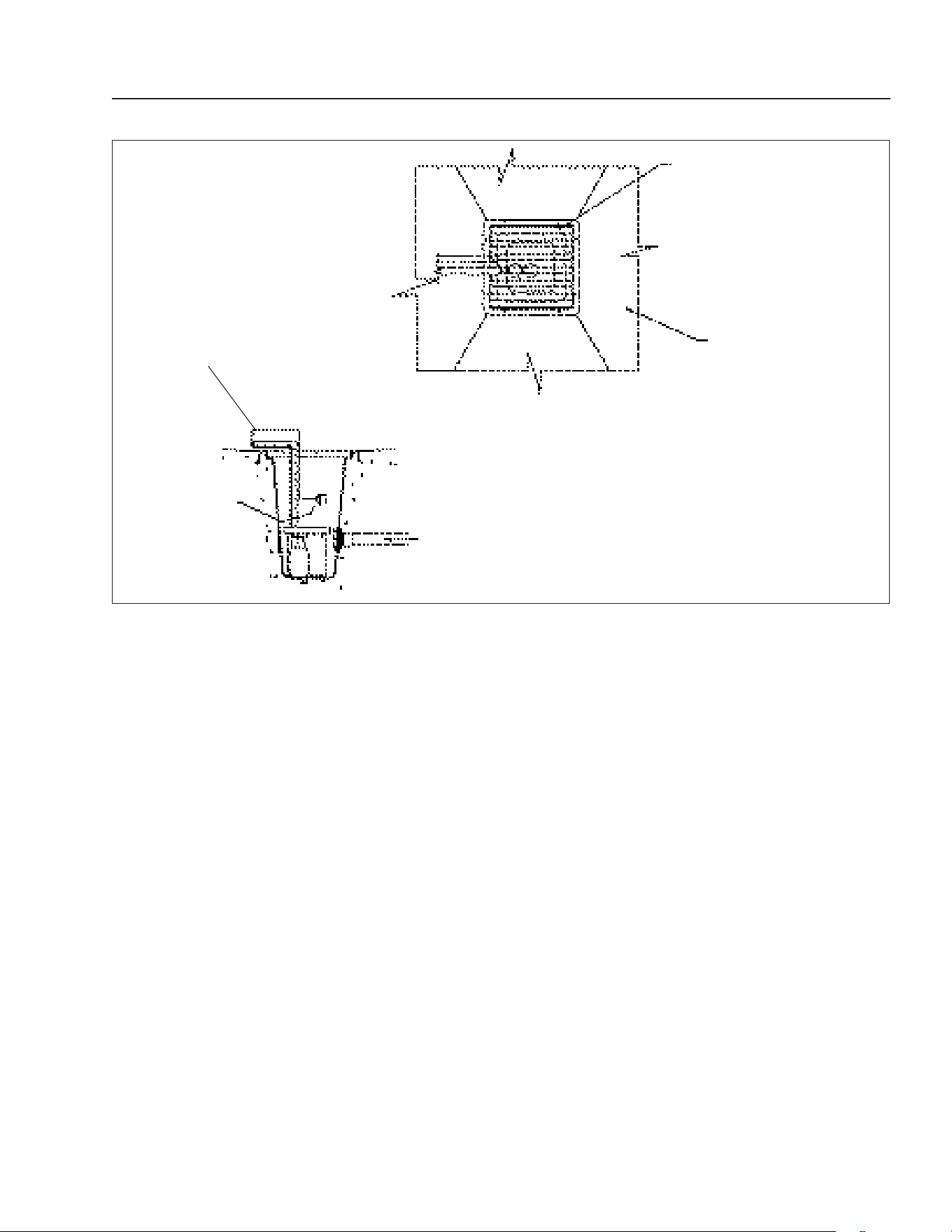
TOP VIEW ALPHA-1500
Figure 3
Oil Skimmer
Vertical Coalescing Plates
Liquid Level Switch
Ozone Generator
Horizontal Coalescing Plates
Drain Manifold
ALPHA SERIES OPERATOR’S MANUAL
9
ALPHA 1500 • #8.913-964.0-J
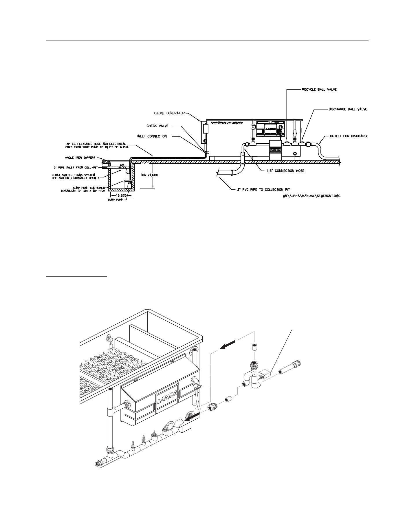
INSTALLATION
AUTO DISCHARGE OPTION
TYPICAL INSTALLATION ALPHA ONLY
(discharged through sewer system)
Electric Ball Valve
Figure 5
Figure 4

10
ALPHA SERIES OPERATOR’S MANUAL
ALPHA 1500 • #8.913-964.0-J
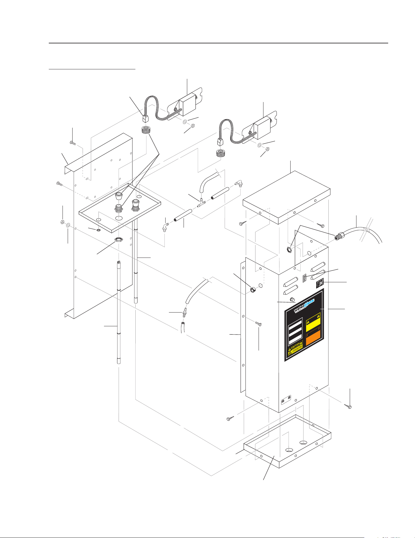
Familiarization With Alpha
The Alpha machine consists of several separate items which
must be installed.
■ The most obvious component is a stainless steel separa-
tor tank which is the heart of the Alpha. Take a minute
to become familiar with this machine.
■ Additional items furnished with the Alpha include:
• Perforated sump pump protection/installation
container.
• Sump pump level on/o oat control for pump.
• 1-1/2" x 16' (3.81 cm x 4.89 m) recycle hose.
• 1-1/2" (3.81 cm) ball valve for recycle system.
• 1-1/2" x 25' (3.81 cm x 7.62 m) inlet hose with quick
connect (cut to length as needed).
• Drain valve manifold
Leveling Alpha Machine
The Alpha Machine must be set level both side to side and
end to end. This is important to assure the machine will
give you optimum performance.
Sump Pump/Level Control
■ Your Alpha comes with a prepackaged perforated pro-
tection container for the sump pump. This container is
designed to protect the pump from clogging and dam-
age from debris. There is a level on/o control attached
to the pump which plugs into the Alpha and then the
pump plugs into the oat control on the Alpha only
installation.
• Insert the Level Control Float Tree into the strain
relief provided on top of the sump pump container
provided.
• Float tether length must be a minimum of
2" (5.08 cm ) long.
• The turno point for the oat level control must be
2" (5.08 cm) above the pump container.
If you have the optional Auto Discharge Kit, refer to
page 20 for proper oat location.
• The oat must travel its complete arc without:
- Water going over top of pit
- Float touching side walls or bottom
- Float interfering with electrical wiring, plumbing,
bottom or side walls of pit, or any other object.
■ Lower the sump pump container, with pump and oat
attached, into the sump. Check to assure the oat can
operate freely.
■ Connect the pump hose to the inlet of the Alpha. This
is a quick connect camlock tting; be sure it is secured.
■ Plug the oat into the electrical outlet on the Alpha and
then plug the power cord for the pump into the back
of the oat.
■ Secure the electrical cords of the pump and the oat to
1-1/2" (3.81 cm) water hose with nylon tie wraps.
Discharge
Connect the 1-1/2" (3.81 cm) discharge line to the male
camlock with the other end into the proper sewer discharge
(see Figure 4).
For discharge, close the recycle ball valve. During the night
or on weekends and holidays, open the recycle ball valve.
Add water to the collection pit until the pump starts.
Connect 1-1/2" (3.81 cm) hose to the recycle port on the
Alpha (see Figure 4). The recycle line should be plumbed
back to the collection pit so when the Alpha is in the re-
cycle mode, the water in all the pits is circulated to control
bacteria.
ORP/pH Controller Option
Install pH/ORP injectors and sensors per drawing on page
28. Install sensor into pipe so sensor tip is half way into pipe,
touching uid, but not touching bottom of pipe. Follow
instructions on page 14 to 15 and instructions that come
with controller.
Auto Discharge Option
Tie wrap the N/C and N/O oats to discharge pipe coming o
sump pump. Position both oats at the same level towards
the upper part of the pit.
Run oat wires to electrical box on Alpha and wire according
to wire diagrams.
When the water level rises and lifts the oats in the pit, the
electric auto discharge valve rotates to discharge water.
When the water level drops and oats fall, the electric ball
valve rotates and directs water back to the pits.
Electrical
The machine, when installed, must be electrically grounded
in accordance with local and/or national codes. Check for
proper electrical supply. Plug the cord into a 120V 15 amp
electrical outlet. It is recommended that a Ground Fault
Circuit Interrupter be installed in the circuit breaker for all
Wash-Water equipment.
NOTE: Always test all electrical outlets for proper voltage
before plugging in any equipment.
ALPHA SERIES OPERATOR’S MANUAL
11
ALPHA 1500 • #8.913-964.0-J
START-UP
Check List Before Starting:
Yes No
1. Is Alpha level from side to side
and end to end? ___ ___
2. Is inlet hose connected to pump
and Alpha? ___ ___
3. Is outlet hose connected to Alpha
and directed to the drain? ___ ___
4. Is the voltage correct? ___ ___
5. Have the pump and oat been
connected to the proper outlet
on Alpha? ___ ___
6. Is the recycle hose attached? ___ ___
Start-Up:
Add water to the sump to activate the oat switch.
Turn the sump pump switch on the Alpha to “ON” (see
Figure 1).
Adjust the length of the Float Level Control to the de-
sired level.
Add additional water to the sump (or Alpha directly)
until the Alpha is full of water (water is exiting the out-
let).
Adjust the height of the gate inside the Alpha that
controls the ow into the oil skimmer. Skim o the oil
with a small amount of water. The oil will stay in the oil
skimmer while the water returns to the pit through the
return line.
Check the machine for leaks (the machine was hy-
drostatically tested at the factory but may have been
damaged in shipment).
Check that the machine is level side to side by observ-
ing the ow over the baes. Shut o the inlet valve and
gradually reopen it. At low ow rates when the machine
is level, ow will be even across the complete top of the
bae.
Check level, end to end, by observing the water level
in relation to the coalescing pack.
Check the overow shuto switch by manually lifting
the liquid level switch (see Figure 3).
Check the recycle line to make sure the water is owing
back to the collection pit.
Figure 6
1. ALL INFORMATION IS FOR REFERENCE ONLY AND IS
INTENDED AS A GUIDELINE TO BE USED BY A PROFES-
SIONAL ENGINEER OR ARCHITECT IN PREPARING A
FINAL DECISION TO MEET THE SPECIFIC SITE REQUIRE-
MENT.
2. WATERMAZE SYSTEM SHOULD BE INCLUDED WITH
PROPER FREEZE PROTECTION.
2' x 2' Removable Steel Grating
Concrete
1-1/2" Supply Hose
to Alpha
3" Pipe from Collection Pit to
Sump Pump
Float #1 (N/O)
Down Will Turn O
Sump Pump

12
ALPHA SERIES OPERATOR’S MANUAL
ALPHA 1500 • #8.913-964.0-J
Start-Up Check List:
Yes No
1. Sump pump plugged into oat
level control on Alpha? ___ ___
2. Sump pump oat control working? ___ ___
3. High level limit switch working? ___ ___
4. Oil skimmer working properly? ___ ___
5. Is water in Alpha level? ___ ___
6. Recycle system working? ___ ___
7. Level control oat working? ___ ___
OPERATION
After start-up, the only operational adjustment on the Al-
pha is the inlet ow control valve (see Figure 1). Your sump
pump owrate may exceed the Alpha’s oil/water separation
capacity. Throttle the valve on the Alpha until the incom-
ing water is the same ow as the recycle water through the
recycle line going back to the collection pit.
This will give adequate ow through the ozone injector
to meter the ozone generator properly (see Figure 8). If at
anytime the incoming ow is adjusted, the ozone generator
must be metered again.
GENERAL MAINTENANCE
AND SERVICE
Periodic Maintenance
Oil Skimmer Collection Tank
Monitor the level of oil in the oil skimmer. Empty
as needed.
Solids Removal
Settled solids are collected in the inlet solids collection
chamber. The solids must be removed periodically as
dictated by the dirt load coming into the machine. The
procedure for removal is as follows.
• Disconnect the machine from the electrical power
source.
• Before opening the drain valve, be sure the ow
of solids is directed to the collection pit. Open each
drain valve individually and remove the solids.
• Remove the vertical coalescing pack (see Figure 3
for location). To remove, lift with the nylon strap that
surrounds the coalescing pack.
• After removal of the vertical coalescing pack, hose
out the remaining solids in the bottom of the
chamber.
• Replace the vertical coalescing pack and close valve.
NOTE: The vertical coalescing pack can be cleaned, if
desired, by washing it with a garden hose or a pres-
sure washer.
• If the solids chamber cannot be drained back to the
collection pit, you can use a shop vac for the Alpha
1500.
Service
Check the electrical cords to assure they are safe, with
no damage or cracking.
Check the inlet and outlet hoses for leaks or damage.

ALPHA SERIES OPERATOR’S MANUAL
13
ALPHA 1500 • #8.913-964.0-J
CHEMICAL MAINTENANCE
PROGRAM
Owner Chemical Maintenance Program to
Maintain Water Quality:
Daily monitoring and adjustment of WATER MAZE water
chemistry is essential. If not monitored and controlled, the
recycled water becomes chemically unbalanced, resulting
in a host of problems such as algae and bacteria growth,
obnoxious odors, iron discoloration and ultimately is unt
for reuse or sewer discharge.
The daily monitoring and adjustment maintenance pro-
gram, if followed, will provide suitable water. The proper
maintenance of the water is not complicated and depends
upon a few basic principles:
1. PHYSICAL - eective ltration and recirculation of
the water
Eective recirculation of the water through the collection
pit, and the Alpha system is achieved only if the system is
utilized often (daily 6-8 hours or more) or if the system is set
to recirculate the water throughout the total system. WATER
MAZE has provided controls and procedures to achieve
continuous eective water recirculation throughout the
process. The Alpha, when operated properly, achieves ef-
fective ltration and recirculation.
2. CHEMICAL - proper adjustment of alkalinity and pH
The most important factor to control and maintain is the
pH of the water (i.e. the acidity or alkalinity). If the water is
acidic (low pH) it will dissolve iron into solution. The pres-
ence of iron of more than 0.2 ppm will result in rusty stain-
ing of virtually anything the water comes in contact with.
Alkaline water can cause cloudiness and greatly reduces the
eectiveness of chlorination. Many cleaning detergents are
alkaline and will make the water too alkaline. The proper pH
range to maintain is 6.8 - 7.2.
Alkalinity refers to the soluble salts in the water. These
include bicarbonates, carbonates, hydroxides and other
alkali compounds. The water's total alkalinity controls its re-
sistance (buering ability) to large uctuations in pH levels.
Another factor which should be monitored for proper water
chemistry balancing is calcium hardness. The presence of
too much calcium can lead to the formulation of scale.
3. BIOLOGICAL - adequate disinfection, bacteria, and
odor control
Chlorination and ozonization are used to control bacteria,
and odor formation. For chlorine to be eective, it must be
available as free chlorine. If the proper pH and alkalinity is
not maintained, or if the water contains dirt particles, the
chlorine will be combined chlorine and not be eective in
the control of algae and bacteria growth. Combined chlorine
has only 1/15th the strength of free chlorine.
Inadequate or improper addition of chlorine could result in
bacteria growth. Once bacterial growth starts, the system
must be shock treated. It is best to minimize the chances
of bacteria problems.
The killing of bacteria by chlorine exists in two phases:
1. The penetration of the active germicidal principal (hy-
pochlorous acid) into the bacterial cell and
2. The chemical combination of this ingredient with the
protoplasm (the complex composition which forms the
essential part of plant and animal cells). This combina-
tion is directly responsible for the death of the organism.
The activity of this germicidal eect is reduced in alkaline
solutions (those with a pH greater than 7.5) and expressed
as follows:
pH % of Eectiveness
4.0 100.0
5.0 99.6
6.0 95.8
7.0 69.7
8.0 18.7
9.0 2.2
10.0 0.2
Hypochlorite when added to solutions with a pH lower
than 6.0 can produce oxide which is toxic. In vehicle wash-
ing, almost all cleaning compounds are alkaline in nature.
Hypochlorite will still control bacterial growth and thus
smell at higher alkaline ranges, but as the table indicates,
its eectiveness is reduced.
To compensate for this inhibited activity, a larger quantity
of hypochlorite is used. This controls bacterial growth, but
also increases operational costs.
Typical hypochlorite has a pH of approximately 11.6. This
high pH increases the pH of holding tank water, making
pH adjustment more dicult.
Trichloro-S-Triazine Trione is a chlorine compound which has
a pH of 3.0 and when added to holding tanks aids in the
reduction of tank pH levels.
Unlike hypochlorite, which is usually 15 percent chlorine and
will produce sodium or calcium salts in holding tanks, these
new products are 99 percent chlorine which means that if
a solid “puck” of chlorine is used, the total eectiveness of
the puck is superior to that of hypochlorite and no negative
by-products are produced.

14
ALPHA SERIES OPERATOR’S MANUAL
ALPHA 1500 • #8.913-964.0-J
OPTIONAL ORP/PH DIGITAL
CONTROLLER - MODEL 250
The Oxidation Reduction Potential (ORP) and pH of the water
stream are controlled automatically by the digital control-
ler. The controller receives input from the ORP sensor on
the activity of the sanitizer and input from the pH sensor
on the pH level of the waste stream. The level of ORP and
pH being sensed and the requested levels programmed in
the controller will determine if outputs from the controller
are sent to the feed pumps. If sanitizer or pH adjustments
are needed, the output will turn the corresponding feed
pump on. This will inject the required sanitizer or pH until
programmed levels are reached and the feed pump will stop.
Acid/Base Jumper
Because most systems are dealing with a high pH situaton,
the controller is factory set for acid feed. If you require a
base feed, turn power o to entire system. Open plastic
door on the controller, remove the four screws on display
board, carefully pull back board and turn over. Reposition
the JP14 jumper to the base position. Return board and
door to original position.
Start-Up
Turn switch on right side of controller to the "ON" position.
Upon power-up the controller will display "109" and then
"ACD" for acid feed or "BSE" for base feed, depending on
your requirements.
Feed Mode
The feed mode for the pH and sanitizer can be set to "OFF",
MANUAL or AUTOMATIC. Set to Automatic. To select the
desired feed mode, press [ORP] or [pH] until the correspond-
ing LED indicator light is illuminated. There is a short delay
before activation. NOTE: Holding the switch for more than
5 seconds resets the setpoint and calibration for [ORP] or
[pH] to original factory values.
ORP Control Setpoint
The ORP setpoint is factory set at 550mV, which is recom-
mended to maintain water quality by killing germs and
bacteria. There is no need for ORP calibration.
The sanitizing concentration required to generate a de-
sired ORP value varies with pH and overall water quality,
particularily Total Dissolved Solids (TDS) concentration and
organic load.
To change the ORP control setpoint:
Press [SETPOINT].
Press [ORP]; the display ashes
Use [UP] and [DOWN] arrows to adjust the ORP value
Press [SETPOINT} again to save the new value.
DAILY CHEMICAL MAINTENANCE
Step 1. Collect a water sample from the outlet of the Alpha.
NOTE: Be sure that the water is circulating from the pit
through the Alpha and back to pit.
Step 2. Using the test strips supplied, measure:
A. The pH.
B. The residual chlorine (systems with chlorine).
C. The alkalinity.
D. The calcium hardness.
Step 3. If the pH is 6.8-7.2 go to Step 4. If not, adjust the pH
of the water that is recycled between the Alpha and the pit
to pH 6.8-7.2. Muriatic acid or Alum can be used to lower the
pH. Soda ash (sodium carbonate) or caustic soda (sodium
hydroxide) can be used to raise the pH.
Adjust the pH gradually, allowing complete mixing after
adding a chemical. Take a new sample, read the pH and
continue to adjust gradually until the desired pH is achieved.
Step 4. The total alkalinity should be between 50-150 ppm.
If the total alkalinity is too low, add sodium bicarbonate to
raise it. If total alkalinity is too high, add muriatic acid to
bring it within acceptable range. This will also decrease the
pH. If the pH goes below 6.8, add sodium bicarbonate to
increase the pH. This procedure may have to be repeated
several times to get the pH and a total alkalinity into the
proper range.
Step 5. The calcium hardness should not exceed 25 grains.
If it is too high, some water must be removed from the sys-
tem and fresh makeup water added. Alternatively, an ion
exchange water softener may have to be added to the sys-
tem to reduce and maintain lower calcium hardness levels.
Step 6. (Systems using a chlorinator) Free chlorine levels
should be 1-2 ppm and must be maintained by adjusting
the ow through the automatic chlorinator, or the regular
addition of liquid chlorine. A 10-50% concentrated liquid
chlorine is available. Household bleach can be used, but
contains only 5% chlorine. Chlorine continually dissipates
and becomes used up and the chlorine level must be ad-
justed daily. Remember, chlorine is most eective when the
pH level is correct (7.0).
Initially, extra time is needed to achieve proper water
chemistry balance. However, once achieved, it can be eas-
ily maintained in a minimum amount of time with daily
monitoring and adjustment.
ALPHA SERIES OPERATOR’S MANUAL
15
ALPHA 1500 • #8.913-964.0-J
pH Calibration
To calibrate the pH, use a reliable, fresh test kit (Phenol Red).
Note the value of the pH and compare it to the display value.
To change the pH calibration:
Press [CALIBRATION]
Press [pH]; the display ashes
Use the [UP] and [DOWN] arrows to adjust the pH value
Press the [CALIBRATION] again to save the new value.
Out-of-Range Alarms
The out-of-range alarms are factory set at 450 and 650mV for
ORP and 6.5 to 7.5 for pH. If the ORP is below the low limit,
the red LED alarm ashes but the sanitizer feed continues.
If the pH limits are exceeded, the red LED alarm ashes and
the pH feeder continues.
To change an alarm limit:
Press [LOW LIMIT] or [HIGH LIMIT]
Use the [UP] and [DOWN] arrows to adjust the value
Press [LOW LIMIT] or [HIGH LIMIT] again.
CAUTION: Increasing the out-of-range limits may casue
overfeeding of chemicals.
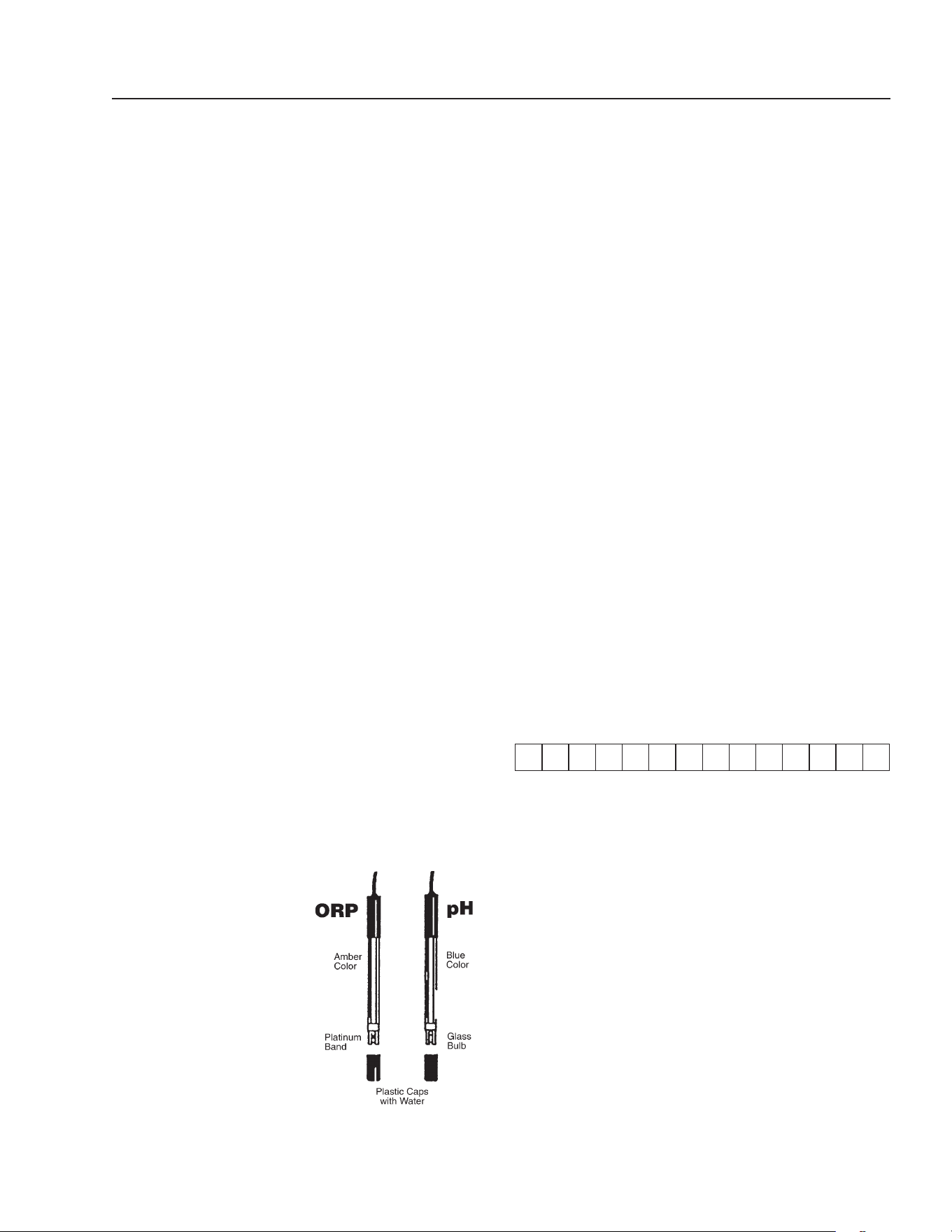
ORP AND PH SENSOR
MAINTENANCE
The controller is virtually maintenance free. The
enclosure and front panel can be cleaned with a soft cloth
moistened with a mild soap and water solution or a glass
cleaner. Do not use abrasives or harsh chemicals.
Sensor Cleaning/Testing
The sensor tips must be kept clean and free from chemical
deposits and contamination to function properly. After
saturation in the waste stream, the sensors may need to be
cleaned on a weekly or monthly basis depending on the wa-
ter quality and other facility-
specic characteristics. Slow
response and inconsistent
readings are indications that
the sensors are in need of
cleaning.
B W G
B W G
B W G
ORP R W B Power pH
Rotary
Flowswitch
Dry-Contact
Alarm
B=black, W=white, G=green, R=red
66-123 66-122
To clean a sensor, carefully remove it from the compression
tting or holding bracket. Clean the tip of the sensor with
a mild liquid detergent (Joy, etc) solution. Rinse with fresh
water and soak the sensor in a mild acid solution for ve
minutes. Rinse with fresh water and reinstall the sensor.
To check sensor for proper operation place a small amount
of white vinegar, muriatic or hydrochloric acid into a cup
and place sensor probe into solution. For the pH sensor,
the needle should drop. For the ORP sensor, the needle
should rise.
NOTE: Only clean one sensor at a time. Sensors must stay
in some kind of liquid at all times.
Sensor Replacement
For preventative maintenance it is also recommended to
replace the sensors on an annual basis or as performance
diminishes.
Sensor Storage
Extended exposure to atmospheric conditions will cause the
sensor tips to dry out. Always remove and properly store the
sensors if they are to be winterized or inactive.
Store the sensors with the original cap provided, making
sure that each cap is lled with clean water. If the storage
containers have been misplaced, store the sensors indi-
vidually in small glass or plastic containers with clean water
covering the sensor tips.
Terminal Block Wiring

16
ALPHA SERIES OPERATOR’S MANUAL
ALPHA 1500 • #8.913-964.0-J
TROUBLESHOOTING - ORP-pH SENSORS
PROBLEM SOLUTION
NO LIGHTS ARE ON
WITH POWER ON
Check for power going to controller.
Check for damaged power connector.
Check internal fuse (1A slow blo) marked F3 on control board.
ILLOGICAL pH AND ORP
VALUE DISPLAYS
The sensor cable connections may be reversed. Verify that
the sensor cables are properly connected to their respective
BNC connectors on the controller unit.
ORP FEEDER
DOES NOT
ACTIVATE
Make sure the AUTO feed light for ORP is on.
Check the ORP setpoint.
Check ORP relay fuse (5A slow blow) marked F2 on control board.
pH FEEDER DOES
NOT ACTIVATE
Verify that the acid/base feed jumper JP14 on the control
board is properly set.
Make sure the AUTO feed light for pH is on.
Check the pH relay fuse (5A slow blow) marked F2 on control board.
pH REQUIRES
FREQUENT
CALIBRATION
Clean or replace the sensor as outlined in the maintenance section.
INCONSISTANT
OR SLOW pH OR
ORP READINGS
Verify that the sensor cables are properly connected to their
respective BNC connectors and the controller unit.
Clean or replace the sensor as outlined in the maintenance section.
Replace the sensors if needed.
CHEMICAL
FEEDER
RUNS
CONTINUOUSLY
Make sure the AUTO feed mode is selected.
Verify that the chemical feeders are properly connected to
their respective connectors or controller unit.
All controllers are manufactured to the highest quality standards and thoroughly tested before leaving the factory. State-
of-the-art designs and fabrication technology should ensure years for trouble-free operation.
ALPHA SERIES OPERATOR’S MANUAL
17
ALPHA 1500 • #8.913-964.0-J
b. Keep work area clean, uncluttered and properly lighted
— replace all unused equipment.
c. Keep visitors at a safe distance from work area.
d. Make workshop childproof — with padlocks, mas-
ter switches, and by removing starter keys.
10. When wiring an electrically driven pump, follow all
electrical and safety codes, as well as the most recent
National Electrical Code (NEC) and the Occupational
Safety and Health Act (OSHA).
DANGER: Risk of electric shock.
This equipment is only for use on 115
volt (single phase) and is equipped
with an approved 3-prong conduc-
tor cord and 3-prong grounding-
type plug (as shown in Figures 1 &
2) for your protection against shock
hazards. It should be plugged di-
rectly into a properly installed and
grounded 3-prong grounding-type
receptacle. It is recommended that
a Ground Fault Circuit Interrupter be installed in the
circuit breaker for all Wash Water equipment.
11. All wiring must be performed by a qualied
electrician.
12. Make certain that the power source conforms to the
requirements of your equipment.
13. Protect the electrical cord from sharp objects, hot sur-
faces, oil, and chemicals. Avoid kinking the cord. Replace
or repair damaged or worn cords immediately.
14. Use wire of adequate size to minimize the voltage drop
at the motor.
15. Disconnect power before servicing a motor or its load.
If the power disconnected is out-of-sight, lock it in the
open position and tag it to prevent unexpected applica-
tion of power.
16. Do not touch an operating motor. Modern motors are
designed to operate at high temperatures.
17. Do not handle a pump or pump motor with wet hands
or when standing on a wet or damp surface, or in water.
18. The pump motor is equipped with an automatic reset-
ting thermal protector and may restart unexpectedly.
Protector tripping is an indication of motor overloading
as a result of operating the pump at low heads (low
discharge restriction), excessively high or low voltage,
inadequate wiring, incorrect motor connections, or a
defective motor or pump.
19. DO NOT run the pump without water. This will
damage the pump.
WARNING
READ OPERATOR’S
MANUAL THOROUGHLY
PRIOR TO USE.
WARNING
READ AND
FOLLOW ALL SAFETY
INSTRUCTIONS TO
AVOID INJURY.
SUBMERSIBLE SUMP PUMPS
WARNING: Read instructions care-
fully before attempting to install,
operate, or service the pump. Protect
yourself and others by observing
all safety information and addi-
tional instructions included with this
equipment. Failure to comply with
instructions could result in personal
injury and/or property damage!
Retain instructions for future refer-
ence.
PUMP SAFETY INFORMATION
1. Know the pump application, limitations, and
potential hazards.
WARNING: Do not use to pump high
concentrations of flammable or
explosive fluids such as gasoline,
fuel oil, kerosene etc. Do not use
in explosive atmospheres. Pump
should only be used with liquids
compatible with pump components
materials. Failure to follow this
warning can result in personal injury
or property damage.
2. Make certain that the power source conforms to the
requirements of your PUMP (115 V).
3. Disconnect power before servicing.
4. Release all pressure within the system before servicing
any component.
5. Drain all liquids from the system before servicing.
6. Secure all lines before starting the pump. An unsecured
line will whip, possibly causing personal injury and/or
property damage.
7. Check hoses for weak or worn condition before each
use, making certain that all connections are secure.
8. Periodically inspect the pump and system components.
Perform routine maintenance as required (see Mainte-
nance).
9. WARNING: Personal Safety:
a. Before servicing the machine,
refer to all MSDS’s on the mate-
rial identied in the waste stream.
You must comply with all warn-
ings and wear all protective
clothing stated on the MSDS’s.
WARNING
RISK OF EXPLOSION: DO
NOT SPRAY
FLAMMABLE LIQUIDS.
TO AVOID
ELECTRICAL SHOCK,
FOLLOW ELECTRICAL AND
SAFETY CODES WHEN
WIRING MACHINE.
DANGER

18
ALPHA SERIES OPERATOR’S MANUAL
ALPHA 1500 • #8.913-964.0-J
PUMP OPERATION
WARNING: Do not touch sump pump, pump motor, water
or discharge piping when the pump is connected to electri-
cal power. Do not handle pump or pump motor with wet
hands or when standing on wet or damp surface, or in
water. Never touch the sump pump or discharge piping
when machine is operating or fails to operate. Always
disconnect the pump cord (power) before handling.
1. The shaft seal depends on water for lubrication. Do
not operate the pump unless it is submerged in water.
Dry running (pump not pumping water) will cause seal
damage and eventual pump failure.
2. The motor is equipped with an automatic reset thermal
protector. This means if the temperature in the motor
should rise unduly, the switch will cut o all power
before damage can be done to the motor. When the
motor has cooled suciently, the switch will reset au-
tomatically and restart the motor. If the protector trips
repeatedly (cycling on protector) the pump should be
removed and checked for the cause of diculty. Low
voltage, long extension cords, clogged impeller, very
low head or lift, etc., can cause cycling. Cycling on the
protector eventually causes motor burnout.
PUMP MAINTENANCE
WARNING: Before attempting to service, disconnect power
from machine. Do not handle pump with wet hands or
when standing on wet or damp surfaces or when in water.
Failure to follow precaution can result in personal injury
and/or property damage.
NOTE: This is a dicult pump to repair, therefore only quali-
ed electricians or servicemen should attempt to repair this
machine. Improper repair and/or assembly can cause an
electrical shock hazard.
Follow recommendation from your pump manufacturer.
PRE-INSTALLATION
SUMP PIT INFORMATION
(For Sump Pit Installation Only)
The sump pump can be installed in a sump pit with a mini-
mum diameter of 18" (45.72 cm) and a depth of 24" (60.96
cm). (Pit dimensions less than these will cause rapid cycling
and shortened pump life). It is recommended that the sump
pit be no smaller than 2' x 2' x 3' (.61 m x .61 m .91 m). The
sump pit may be constructed of tile, concrete, steel, ber-
glass or plastic. Check local codes for approved materials.
Make sure there are no small stones, gravel, sand, dirt silt,
etc. that may clog or damage the pump and/or pump seal,
and cause pump failure. If there are stones or gravel, clean
these out before installing the pump. Test pump for proper
operation (see Operation) before installing sump pit cover.
A sump pit cover will prevent debris from possibly clogging
or damaging the pump. It will also prevent persons from
falling in and causing injury to themselves. If an existing
pit is being used, it must be thoroughly cleaned before
installation.
SUMP PUMP INSTALLATION
WARNING: This sump pump is not designed for use in septic
tanks or underground vaults to handle raw sewage or ef-
uents. It should never be used in hazardous or explosive
locations. Do not use power cord to lift motor. Always use
the handle.
1. The sump pump should not be suspended by means of
the discharge pipe or power cord. Instead it should be
resting on a solid foundation in the bottom of the pit.
Clean the sump pit of small stones, gravel, sand, dirt,
silt, etc., which could clog or damage pump, pump seal,
and cause pump failure.
2. The sump pump is designed for 115 V, 60 HZ operation
and requires a circuit of 15 amperes. It is supplied with
a 3-wire cord set with a grounding-type plug for use in
a 3-wire, grounded outlet. For safety, the pump should
always be electrically grounded to a suitable electrical
ground such as a grounded water pipe or a properly
grounded metallic raceway, or ground wire system.
3. After all piping and controls have been installed, the
machine is ready for operation.
ALPHA SERIES OPERATOR’S MANUAL
19
ALPHA 1500 • #8.913-964.0-J
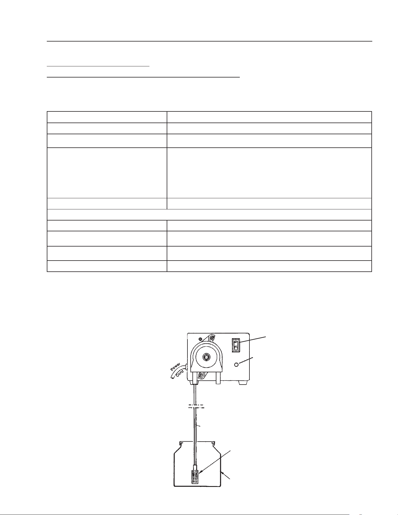
SERIES VARIABLE SPEED
PERISTALTIC METERING PUMP MODELS VSP 20
#5-2360 TECHNICAL INFORMATION
INSTALLATION DIAGRAM
Feed Rate 2.6 - 20 GPD
Tubing Size 7/16" O.D. x 1/4" I.D.
Dimensions 5" H x 6-1/4" W x7" D
Standard Accessories Included Head Tubing
Injection Fitting with Check Valve
Strainer
Polyethylene Tubing (1/4 O.D. x 15)
Tubing Sleeve (for strainer connection)
Electrical Rating 115V 50/60Hz
Materials:
Pump Head Polycarbonate
Pump Head Tubing Special Synthetic Rubber
Strainer and Injection Point Fitting PVC
Maximum System Pressure 25 psi (maximum allowed at injection tting)
Figure 7
Suction
Tubing
Enclosure Cap
Strainer
Chemical
Container
On/O
Switch
20
ALPHA SERIES OPERATOR’S MANUAL
ALPHA 1500 • #8.913-964.0-J
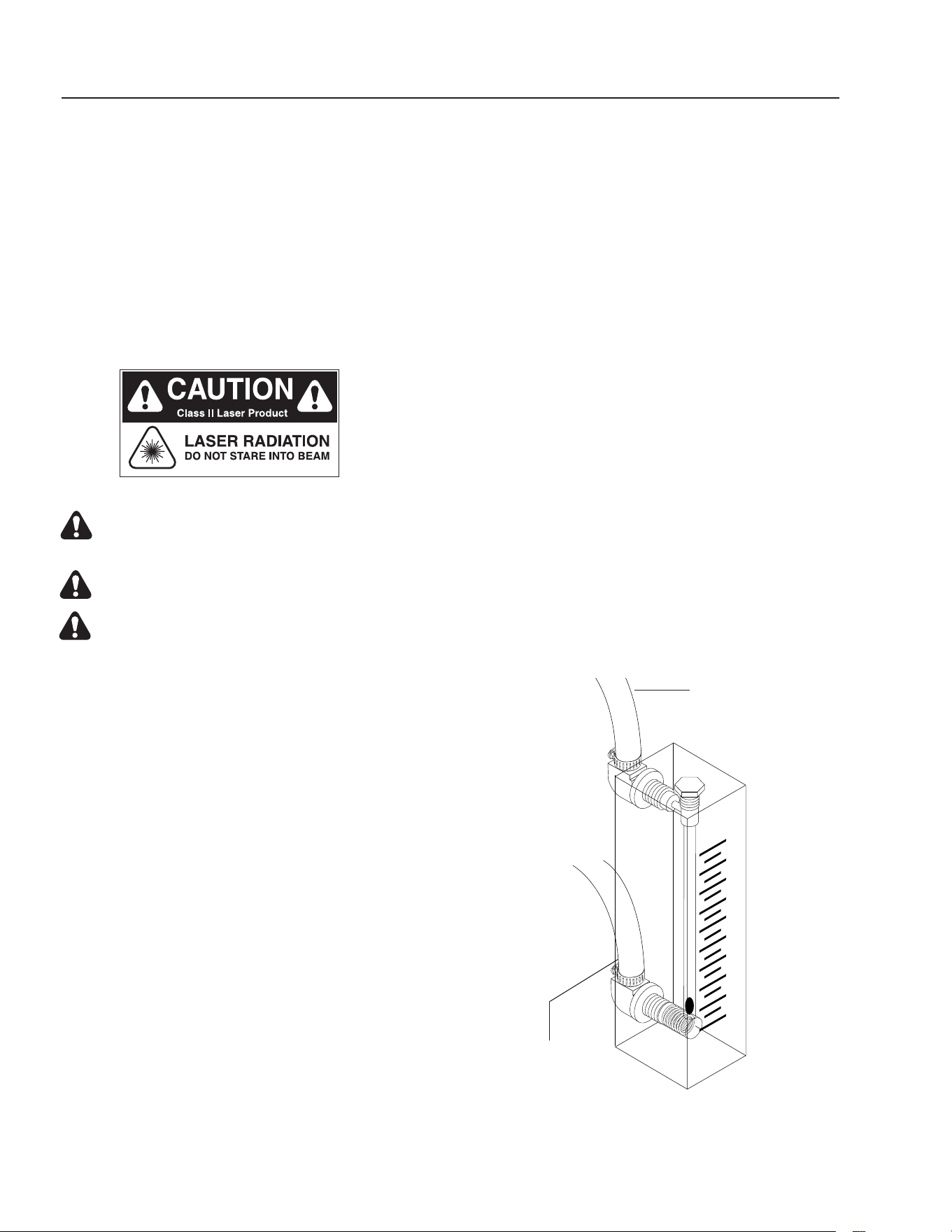
ULTRAVIOLET LIGHT
COMPLIANCE
Ultraviolet Light Safety Requirements
The device used in this product is a Class 1 certified
ozone generator product. Operating this product outside
specifications or altering its original design may result
in hazardous radiation exposure, and may be considered
an act of modifying or new manufacturing of a laser
product under U.S. regulations contained in 21CFR
Chapter 1, subchapter J.
CAUTION: Avoid exposure to direct or
strongly reected germicidal ultraviolet rays.
DO NOT STARE INTO BEAM.
DANGER: Ultraviolet radiation.
Disconnect Power Before Replacing Lamp.
DANGER: Connect only to a circuit that is protected
by Ground Fault Circuit Interrupt (GFCI).
Instructions for disposing of your UV
Light Tube
1. Do not break a UV Light Tube. Keep all tubes whole
if possible. If a UV Light Tube is accidentally bro-
ken, wear gloves while picking up the pieces, and
carefully dispose of them in a trash bag. Wipe the area
with a wet wipe, and put the wet wipe in the same
trash bag. Place the trash bag with broken pieces
inside another trash bag. Mark the bag with a sign
labeled, "Broken Mercury Light Bulb".
2. Remove the UV Light Tube from the Ozone Generator.
Place the used tube in the trash bag, and place that
bag inside another trash bag. Seal the openings
and then tape a slip of paper on the outer bag labeled,
"Mercury LIght Bulb."
3. Take the used and /or broken mercury tube to your
nearest recycling bin for mercury light bulbs..or take
this tube to a state-approved recycling center.
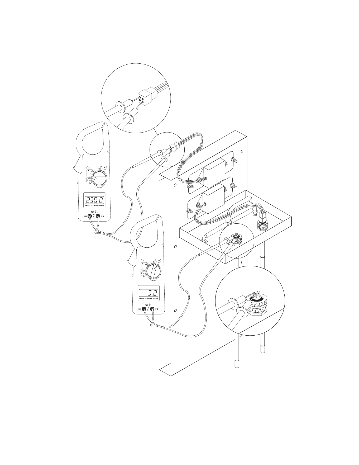
OZONE GENERATOR OPERATION
The indicator light on the Ozone Generator will have a dim
green light or no light if the machine is working. It will have
a bright green light if the machine has a malfunction.
Setting the Ozone Generator
An SCFH (Standard Cubic Feet per Hour) gauge is used to
accurately measure the amount of air owing through the
ozone delivery line, or in other words, the amount of ozone
being injected into the water
1. With the pump running, disconnect the tubing from
the ozone check valve and connect the tubing to the
bottom tting on the gauge. This tube is from the ozone
generator.
2. While holding the gauge vertically, connect the tub-
ing from the top of the gauge to the ozone injec-
tor and read the amount indicated on the gauge.
NOTE: You are measuring suction, so make sure tubing
is attached properly.
3. Begin adjusting metering valve until a 10 SCFH ow for
the Series 101 is achieved on the SCFH gauge. NOTE:
Series 200 is set at 20 SCFH and Series 400 at 40 SCFH.
The Alpha machine comes with series 101 standards.
4. Reconnect tubing to the ozone check valve.
SCFH AIR
50
40
10
20
30
Figure 8
From
Ozone Generator
(keep gauge vertical)
Attach Tube from
Ozone Generator

ALPHA SERIES OPERATOR’S MANUAL
21
ALPHA 1500 • #8.913-964.0-J
OZONE GENERATOR
MAINTENANCE
CAUTION: Never look at the unshielded ozone
lamp while operating the machine. This lamp can
cause severe eye and skin damage. There is a green
indicator light that will turn bright green
if there is a problem. It will be OFF to DIM under
normal running conditions.
Lamp: The lamp has a 9,000 hour life expectancy.
Testing the Lamps:
To test the ozone lamp use a voltmeter set on ohms.
First remove the ozone cover and unplug the lamp plug
from the ozone lamp. NOTE: There are two filaments,
an upper and a lower, inside the lamp. Place one of the
voltmeter leads on one of the lamp prongs and with
the other lead, touch all of the three remaining prongs.
If continuity is not achieved, replace the ozone lamp
(Part #8.716-600.0). You should get continuity from two
prongs for the upper filament and from the other two
prongs for the lower lament (see diagram on page 25).
To test the ballast, use a voltmeter set on the correct voltage
(120V). Place one of the voltmeter leads into the lamp plug
where the white wire goes into it and plug the other voltme-
ter lead into the lamp plug where the blue wire goes into it.
If no voltage is present, replace the ballast (Part #8.716-590.0
- 120V). If the lamp has continuity and the voltage is good
on the ballast but the lamp still will not come on, there is a
problem with the starter inside the ballast and the ballast
must be replaced.
Replacing the Lamps:
Replacement lamps are available from your Water Maze
Dealer should one be needed. Simply turn o the power,
remove the two screws on the power pack cover and remove
the cover. Disconnect the plug on the end of the ozone lamp.
Now, loosen the lamp holder locking ring from around the
end of the lamp by turning it counter clockwise and remove
it. Remove the lamp by grabbing the rubber bushing around
the end of the lamp and pulling it straight out. Remove the
rubber bushing from the lamp and install it on your new
lamp, making sure the outer edge of the bushing is ush
with the outer edge of the silver end cap on the lamp. Now,
slide the lamp back into the reaction chamber. The lamp
holder may now be reinstalled and tightened. Reinstall the
plug onto the lamp and replace the pack cover.
CAUTION: Keep the lamp free of ngerprints and dust par-
ticles. Handle only the metal end caps. You can clean the
lamp with rubbing alcohol and a soft cloth. A dirty lamp
will not allow maximum ozone output.
22
ALPHA SERIES OPERATOR’S MANUAL
ALPHA 1500 • #8.913-964.0-J
OZONE GENERATOR TESTING
SPECIFICATIONS
Energy required 110V: 105 VAC MIN.,125VAC
MAX., .800 AMP
Power Consumption: 20 Watts
Average Lamp Life: 9,000 Hours
Lamp Wavelength: 185 nm
Dimensions: 10½" x 23½" x 8" (26.67 cm x 59.69 cm x 20.32 cm)
89139640-6
ALPHA SERIES OPERATOR’S MANUAL
23
ALPHA 1500 • #8.913-964.0-J
89139640-1
C
O
NFO
RMS TO
UL STD.
73
CE
R
TIFIE
D TO
C
AN/
C
SA
C22.
2
NO. 68
ETL
L
I
STED
OZONE GENERATOR
DISCO
NNECT
FROM ELECTRICAL
SUPPL
Y BEFO
RE SERVI
CING.
DESC
ONE
CTE LA C
ORRIE
N
TE
E
LEC
TRICA
ANTES DE
DA
R SER
VICI
O.
C
OUPE
R
L’ALIMENT
A
T
ION
ÉLECTRI
QU
E
AVANT
D
E
FA
I
R
E
UNE
RÉPA
R
ATION
.
DISCO
NNECT
F
R
OM ELECTRICAL
SUPP
L
Y BEFO
RE SERVI
CING.
DESC
ONE
CTE LA C
ORRIE
NTE
E
LEC
TRICA
ANTES DE
D
A
R SER
VICIO.
C
OUPE
R
L’ALIMEN
T
AT
ION
ÉLECTRIQU
E
AVANT
D
E
FA
I
R
E
UNE
RÉPA
R
ATION
.
INDIC
ATOR LIGH
T OPER
A
T
ION
A
b
right
co
nti
nuous lig
h
t
i
ndicates
UV
l
i
ght
or b
a
llast defe
cti
v
e.
U
n
a
lu
z
lum
inosa
i
ndica que
l
a
l
u
z
u
l
tra-
vi
o
let
a
o t
r
a
n
s
formado
r está d
e
f
ectu
o
so.
U
n
e
lu
mière
claire i
n
diq
ue q
u
e
la l
u
m
ière
u
l
travio
l
e
tte
o
u
le
tr
a
n
sf
ormat
eur es
t
d
éfectu
e
u
x.
OPERA
CION DE
LA
LUZ
IN
D
ICAD
ORA
OPÉRATION
DE LE LAMPE
IN
D
IC
ATEUR
HOT!
CALIENTE!
CHAUD!
CAUTION
PRECAUCI
ON
ATTENTION
8
.90
0
-455.
0
!
WARNING!
AT
E
NCIO
N
!/ ATTENTIO
N!
!
OZONE GENERATOR
PARTS BREAKDOWN
20
2
19
12
14
18
24
22
17
15
13
9
23
7
4
10
23
9
21
22
1
11
6
16
26
8
3
5
7
21
9
23
25

24
ALPHA SERIES OPERATOR’S MANUAL
ALPHA 1500 • #8.913-964.0-J
OZONE GENERATOR • SERIES 101
PARTS LIST
ITEM PART NO. DESCRIPTION QTY
1 8.913-351.0 Ozone Box, Back, 200 1
2 8.913-356.0 Ozone Box, Front, 200 1
3 9.802-455.0 Light, Indicator, Green,
125V 2
4 9.802-523.0 Locknut, 3/4" (19.05 mm)
Conduit 2
5 8.716-583.0 Connector, Aluminum Cord
SCH1037 2
6 8.716-592.0 Connector, 4 Pin Plug 2
7 8.716-600.0 Lamp, Ozone Replacement 2
8 8.707-355.0 Ozone Check Valve 1
9 9.802-696.0 Nut, 10/32" (7.94 mm)
NF ST ST KEP 10
10 8.706-570.0 Locknut, 3/8" (9.53 mm)
Nylon 2
11 8.706-585.0 Connector, 3/8" x 3/8"
(9.53 mm x (9.53 mm), Male
Elbow (Kynar) 2
12 8.706-594.0 Tee, 3/8" (9.53 mm) (Kynar) 1
13 8.706-733.0 Bushing, 1/2" (12.7 mm)
Snap 1
14 8.711-733.0 Tubing, 3/8" x 1/2"
(9.53 mm x 12.7 mm)
Clear Vinyl 7 ft.
15 9.802-423.0 Cord, Service, SEO, 16/3
(30.48) 9 ft.
ITEM PART NO. DESCRIPTION QTY
16 8.716-051.0 Switch, Curvette
120V & 220V 1
17 9.802-514.0 Strain Relief, LT, Str
1/2" NPT, .23-.45D 1
18 8.706-544.0 Cushion, 1/2" x 8-3/4" x 5-3/4"
( 12.7 mm x 22.23 cm x
14.61 cm) 200 1
19 8.913-352.0 Ozone Box , Top, 200 1
20 8.913-353.0 Ozone Box, Bottom, 200 1
21 8.716-590.0 Ballast, 120/230 Volt
Ozone Generator 2
22 9.802-698.0 Screw, 10-32" x 1/2"
Slot Pan MS 10
23 8.718-959.0 Washer, #10 Flat, SS 11
24 8.718-940.0 Screw, #10 x 3/4"
HWH TEK SS 8
25 8.758-525.0 Label, Ozone Generator 1
ALPHA SERIES OPERATOR’S MANUAL
25
ALPHA 1500 • #8.913-964.0-J
INLET SIDE (Front)
ALPHA-1500
▲
5
4
15
3
9 7 8 10 11 26
17
1
12
19
13
▲
▲
2
14
18
16
21
20

26
ALPHA SERIES OPERATOR’S MANUAL
ALPHA 1500 • #8.913-964.0-J
ITEM PART NO. DESCRIPTION QTY
1 8.707-300.0 Valve, 1" PVC Ball Check 1
2 8.706-485.0 Bulkhead, Cycl. 1-1/2"
(3.81 cm) PVC SP 1023 2
3 8.706-423.0 Hanger, Pipe, 1" (3.81 cm)
Clic #32 1
4 8.707-355.0 Valve, 3/8" Tubing Check
S-46-01-0008 1
5 8.711-733.0 Tubing, 3/8" x 1/2"
Clear Vinyl /ft. (30.48 cm) 3
6 8.905-707.0 Ozone Generator,
Series 101 (120V) 1
7 9.802-453.0 Switch, Curvette,
120V & 220V 2
8 8.716-257.0 ▲ Relay, Power Omron
G4B112T FDCUSRPAC 120 1
9.802-475.0 Box, Plastic, 8" x 8" x 4"
(20.32 cm x 20.32 cm x
10.16 cm), w/Lid 1
8.913-330.0 Panel Control, Alpha 1
9 9.802-514.0 Strain Relief 2
10 8.716-319.0 Receptacle, Duplex, 115V 1
8.716-320.0 Cover, SC, Duplex, 3780SC 1
ITEM PART NO. DESCRIPTION QTY
11 8.913-335.0 Tank Assy Welded,
Alpha 1500 Stainless Steel 1
12 8.707-169.0 Camlock, 1-1/2" (3.81 cm)
Male x MPT 1
13 8.716-572.0
Connector, Strain Relief,
TB2522
1
14 8.716-307.0 Plug Male, 115V, 15 amp
Heavy Duty 1
15 8.707-343.0 Valve Gate, PVC 1"
(2.54 cm), FIPT x FIPT 1
16 8.706-588.0 Connector, Male Elbow, Pol
3/8" x 1/4" 1
17 8.707-321.0 Valve, Ozone Metering,
Plastic 1
18 8.706-587.0 Nipple, Hex Red, 1/2" x 1/4"
(12.7 mm x 6.35 mm) (Poly) 1
19 8.709-431.0 Injector, Ozone
20 8.706-394.0 Plug, 1-1/2" (3.81 cm)
PVC 80 1
21 8.706-404.0 Bushing, 1-1/2" x 1"
(5.08 mm x 3.81 cm)
MT x FT, PVC 80 1
▲ Not Shown
INLET SIDE (Front)
ALPHA-1500
ALPHA SERIES OPERATOR’S MANUAL
27
ALPHA 1500 • #8.913-964.0-J
RIGHT SIDE VIEW
ALPHA 1500
89139640-4
33
37
36
31
30
35
32
34
29
38
8
1
2
24
25
26
28
25
26
pH/ORP
Controller
Option
pH/ORP
Injector
16
23
18
39
23
16
pH/ORP
Sensors
14
19
17
21
16
20
15
1
15
14
16
12
21
4
13
7
9
11
12
17
6
3
5
pH/ORP
Controller
Option
10
27
22
40

28
ALPHA SERIES OPERATOR’S MANUAL
ALPHA 1500 • #8.913-964.0-J
ITEM PART NO. DESCRIPTION QTY
1 8.706-469.0 Union, 1-1/2" (3.81 cm)
S x S 2
2 8.706-428.0 Tee, 1-1/2" (3.81 cm)
S x S x T 2
3 8.706-372.0 ▲ Elbow, 1-1/2" (3.81 cm)
SLIP x FIPT, PVC 80, 90° 1
4 8.707-021.0 Push-On Barb 3/4" x 3/4"
(19.05 mm x 19.05 mm)
MPT 1
5 8.706-424.0 Nipple, PVC 80 1-1/2"
(3.81 cm) 1
6 8.913-338.0 ▲ Slide, Stainless 1
8.913-337.0 ▲ Trough Assembly 1
7 8.706-377.0 Elbow, 90° 3/4" (19.05 mm)
FIPT x FIPT 1
8 8.933-048.0 Oil Skimmer/Float Tank Assy 1
9 9.802-052.0 Bulkhead, 3/4" (19.05 mm)
Plastic 1
10 8.750-743.0 ▲ Bulkhead, 1/2"
Polypro 2
8.706-387.0 ▲ Plug, 1/2" MIPT, PVC 80 1
11 8.706-485.0 Bulkhead, Cyc. 1-1/2"
(3.81 cm) SP1023 5
12 8.706-394.0 Plug, 1-1/2" (3.81 cm),
PVC 80 3
13 8.707-359.0 Ball Valve, 3/4" (19.05 mm)
PVC 1
14 8.707-361.0 Valve, 1-1/2" S x S 2
15 8.707-169.0 Adapter, 1-1/2" Male x 1-1/2"
Male Thrd Camlock
(3.81 cm x 3.81 cm) 2
16 8.706-426.0 Tee, 1-1/2" S x S x S 6
17 8.706-485.0 Bulkhead, Cyc, 1-1/2"
(3.81 cm) SP 1023 5
18 8.716-986.0 Injector 2
19 9.802-261.0 Hose, Push-On, 3/4"
(19.05 mm) (30.48 cm) 1.5 ft.
ITEM PART NO. DESCRIPTION QTY
20 8.706-448.0 Adapter, 1-1/2" FT x 1-1/2"
Slip (3.81 cm x 3.81 cm) 2
21 8.706-379.0 Elbow, 1-1/2" Slip x Slip
PVC 80, 45° 4
22 8.706-407.0 Bushing, 1/2" x 1/4"
MT x FT 2
23 8.706-406.0 Bushing, 1-1/2" x 1/2"
SPG x FT 4
24 8.716-990.0 Controller Only, CH250
ORP/pH, Digital 1
25 8.715-378.0 Pump, Metering, 24V 2
26 8.716-984.0 Tubing, 15' Roll 2
8.711-736.0 ▲ Tube 2 ft.
27 8.716-905.0 Sensor, pH 1
8.716-906.0 ▲ Sensor, ORP 1
28 8.913-307.0 Bracket, pH/ORP Controller 1
29 8.930-674.0 Electrical box Alpha 1
- 8.934-422.0 Electrical box Alpha w/ Option 1
30 8.716-319.0 Receptacle, Duplex, 115V 1
31 8.716-257.0 Relay, Power Omron 1
32 9.802-453.0 Switch, Curvette 1
33 9.802-515.0 Strain Relief 2
34 9.802-428.0 Cord, Electric, 12/3 15ft
35 8.758-696.0 Label, Alpha-3100
Control Panel 1
36 9.802-553.0 Transformer, Micron,
120/240V-24V, .050 KVA 1
37 9.803-663.0 Fuse, KTK-R2, 600V 2
38 9.803-977.0 Fuse, 2-1/2 Amp, 250V 1
39 8.716-970.0 Compression Fitting 2
40 8.758-514.0 Label, Assembled In
USA Generic 1
▲ Not Shown
RIGHT SIDE VIEW
ALPHA 1500 PARTS LIST
ALPHA SERIES OPERATOR’S MANUAL
29
ALPHA 1500 • #8.913-964.0-J
DISCHARGE SIDE
ALL MODELS
ITEM PART NO. DESCRIPTION QTY
1 8.707-169.0 Camlock, 1-1/2" (3.81 cm)
Male x MPT 2
2 8.707-361.0 Valve Ball, PVC 1-1/2" (3.81 cm)
S x S 2
3 8.706-424.0 Nipple, PVC 80, 1-1/2" (3.81 cm)
Close 1
1
2
3
30
ALPHA SERIES OPERATOR’S MANUAL
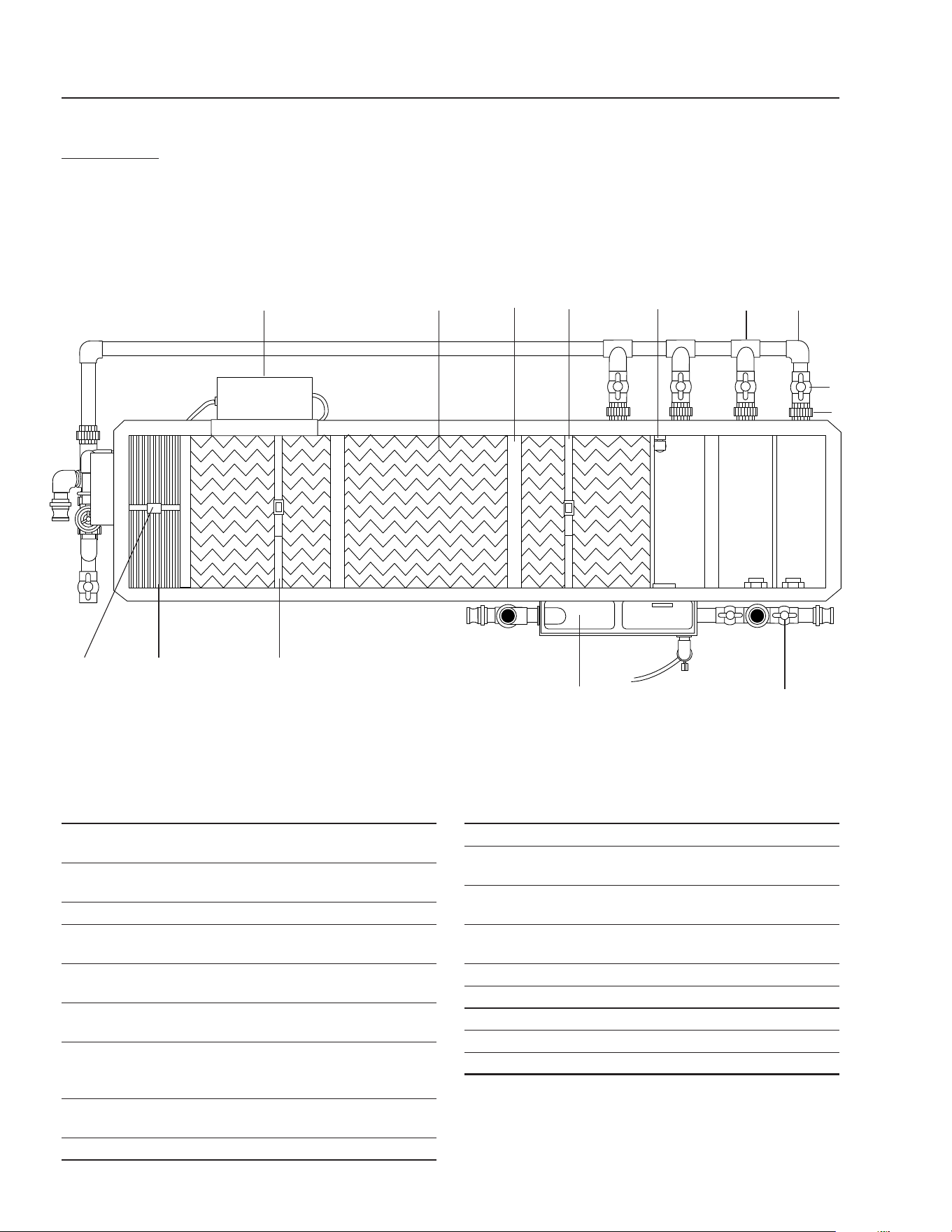
ALPHA 1500 • #8.913-964.0-J
TOP VIEW
ALPHA-1500
ITEM PART NO. DESCRIPTION QTY
1 8.905-707.0 Ozone Generator Series 101
(120v) 1
8.716-600.0 ▲ Lamp, S-1200 Ozone
Replacement 1
8.716-592.0 ▲ Connector, 4 Pin Plug 1
8.716-588.0 ▲ Ballast, 120v, Ozone
Generator 1
2 8.706-671.0 Grid, Horizontal Coalescing
Alpha-1500 16
8.706-675.0 Grid, Horizontal Coalescing
Alpha-1500 16
3 8.709-339.0 Strap, Coalescing Grid, 112"
(284.48 cm) Alpha-500 1
Alpha-1500 2
4 8.913-304.0 Retainer, Coalescing Pack,
SS Alpha 1
5 8.716-632.0 Switch, Liquid Level 1
ITEM PART NO. DESCRIPTION QTY
6 8.903-588.0 Oil Skimmer Assembly 1
7 8.707-361.0 Valve, Ball, 1-1/2" (3.81 cm)
S x S 2
8 8.706-668.0 Grid, Vertical Coalescing
Alpha 4
9 8.709-338.0 Strap Coalescing Grid, 60"
(152.4 cm) 1
10 8.706-374.0 Elbow, 1.5" SxS PVC 80 90° 2
11 8.706-469.0 Union, 1.5" SxS, PVC 80 5
8.706-441.0 ▲ Adaptor, 1.5" SxMT 5
12 8.707-361.0 Valve 1.5" S80 PVC SxS 5
13 8.706-426.0 Tee, 1.5" SxSxS, PVC 80 4
▲ Not Shown
1 2
3
4 5
6 7
8
9
3
10
11
12
13

ALPHA SERIES OPERATOR’S MANUAL
31
ALPHA 1500 • #8.913-964.0-J
PROBLEM POSSIBLE CAUSE SOLUTION
NO FLOW OF
WATER INTO
ALPHA
Control switch not in "ON" position Turn switch to "ON" position.
Water in sump not high enough
to activate level switch
Lift oat level switch and
see if pump turns on.
Alpha not plugged in Plug in Alpha.
High level limit switch shut o Check on/o functioning.
Adjust, repair or replace.
Debris in pump impeller Unplug pump and remove from container.
Check impeller. Clean/repair.
Flow control valve in "OFF" position Open valve.
Dirt collection chamber full Drain and clean.
Dirt lodged in control
valve or check valve
Clean as needed.
Frozen water in lines or valves Thaw out with warm water.
EXCESSIVE
WATER FLOWING
INTO OIL
SKIMMER
Tank not level end to
end or side to side
Level tank.
High level limit switch not functioning Check ON/OFF functioning.
Adjust, repair or replace.
Water coming into Alpha
faster than machine is rated for
Adjust ow control valve.
Discharge line plugged or valve closed Remove obstruction or open valve.
TROUBLESHOOTING

32
ALPHA SERIES OPERATOR’S MANUAL
ALPHA 1500 • #8.913-964.0-J
TROUBLESHOOTING
PROBLEM POSSIBLE CAUSE SOLUTION
PUMP WON'T
START
Tripped breaker Reset breaker.
Low line voltage If voltage under recommended minimum,
check size of wiring from main switch
on property. If OK, contact power company.
Defective motor Replace motor.
Pump lled with mud or debris Remove pump base and clean
out mud or debris.
PUMP STARTS
AND STOPS
TOO OFTEN
Low line voltage If voltage under recommended minimum,
check size of wiring from main switch on
property. If OK, contact power company.
Long extension cords Shorten extension cord.
Clogged impeller Remove housing, unclog.
Faulty motor protector Replace pump.
Very low head or lift Increase head or lift.
Back ow of water from
long discharge line
Add check valve as close as
possible to pump (see installation).
Sump pit too small Increase size of pit.
PUMP WON'T
SHUT OFF
Defective oat switch Replace.
PUMP OPERATED
BUT DELIVERS
LITTLE OR
NO WATER
Low line voltage If voltage under recommended minimum,
check size of wiring from main switch on
property. If OK, contact power company.
Fouled sediment screen Clean, repair or replace as needed.
Worn or defective pump
parts or plugged impeller
Replace worn parts or entire pump.
Clean parts if required.
Pump air locked Turn pump "On-O" several times.
Fill hose manually with water.
Wear plate and impeller worn Check and replace if needed.

ALPHA SERIES OPERATOR’S MANUAL
33
ALPHA 1500 • #8.913-964.0-J
PREVENTATIVE MAINTENANCE
This Alpha machine was produced with the best available materials and quality craftsmanship. However, you as the owner
have certain responsibilities for the correct care of the equipment. Attention to regular preventative maintenance proce-
dures will assist in preserving the performance of your equipment. Contact your WATER MAZE, Inc. dealer for maintenance.
Regular preventative maintenance will add many hours to the life of your pressure washer. Perform maintenance more
often under severe conditions.
MAINTENANCE SCHEDULE
System Flow Rate - Check visually
Alpha 3100 - Completely covering exit pipe
All Units: Make sure the overow switch in the coalescing chamber is not "cycling"
Daily
Exit Pipe - Check for obstructions Daily
Ozone Generator - Check indicator light. (light "on" indicates malfunction) Daily
Check control panel to make sure switches are on and voltage is connected to unit Daily
Check all plumbing for leaks Daily
Check water chemistry and make needed adjustments Daily
Coalescing Chamber - Check for solids accumulation. Clean out if over 4" of solids Weekly
Ozone Generator - Check air ow. Set to 10 SCFM Monthly
Inlet (rst) Chamber - Check for solids accumulation. Clean as required Monthly
Suck sludge and debris from pits Monthly
Check sump pump and if necessary clean out dirt and debris Monthly
Clean dirt or grease from oat Monthly
Check oat wires for cuts or frays Monthly
Coalescing Plates - Remove and inspect. Clean with warm water - no detergents.
When reinstalling make sure pack ts snug to bottom
Monthly
Oil Skimmer - Drain o oil layer if over 1/2" (12.7 mm) thick.
Close drain when done. Check input ow to skimmer.
Adjust "slot" height for ow rate of "just a trickle"
Monthly or as needed
Ozone Generator Bulb - Replace As needed

34
ALPHA SERIES OPERATOR’S MANUAL
ALPHA 1500 • #8.913-964.0-J
SPECIFICATIONS
MODEL ALPHA 1500
FLOW RANGE GPM (LPM) 0-15 (56.78)
HOLDING CAPACITY GAL (LTR) 125 (473.13)
ELECTRICAL V/AMP 120/12
COALESCING PACK 500 sq.ft. (152.35)
OZONATOR Series 200
SUMP PUMP (RECOMMENDED) 1/2 HP, 120V (.37 kw)
OIL SKIMMER Manual
TANK MATERIAL Stainless Steel
DIMENSIONS L/W/H IN (CM) 80/36/31"
(203.2/91.44/78.74)
MACHINE ONLY WEIGHT LBS (KG) 325 (147.73)
SHIPPING WEIGHT LBS (KG) 545 (247.73)

ALPHA SERIES OPERATOR’S MANUAL
35
ALPHA 1500 • #8.913-964.0-J

ALPHA SERIES OPERATOR’S MANUAL
36
Alpha • 1500 • #8.913-964.0-J
LIMITED NEW PRODUCT WARRANTY
WASH WATER / WATER TREATMENT SYSTEMS
WHAT THIS WARRANTY COVERS
All
WATER MAZE
water treatment systems are warranted by to the original purchaser to be free from defects in materials
and workmanship under normal use, for the periods specified below. This Limited Warranty, subject to the exclusions shown
below, is calculated from the date of the original purchase, and applies to the original components only. Any parts replaced
under this warranty will assume the remainder of the part’s warranty period. A 60 day grace period will be given for installa-
tion.
ONE YEAR PARTS AND 30 DAY LABOR WARRANTY:
All components excluding normal wear items as described below.
WARRANTY PROVIDED BY OTHER MANUFACTURERS:
Motors, which are warranted by their respective manufacturers, are serviced through these manufacturers’ local authorized
service centers.
WATER MAZE
cannot provide warranty on these items.
WHAT THIS WARRANTY DOES NOT COVER
This warranty does not cover the following items:
1. Normal wear items, such as seals, filters, gaskets, O-rings, packings, pistons, brushes, filtering media, ozone
bulbs, sensors, UV scanners, oil-skimmer belt, impedance sensor. Minor leaks covered first time on original start-
up only.
2. Damage or malfunctions resulting from accidents, abuse, modifications, alterations, incorrect installation, improper
servicing, failure to follow
manufacturer’s maintenance instructions, or use of the equipment beyond its stated
usage specifications as contained in the operator’s manual.
3. Damage due to freezing, sludge build-up, chemical deterioration (oxidation, chloride or fluoride corrosion), and
rust.
4. Damage to components from fluctuations in electrical or water supply.
5. Normal maintenance service, including adjustments.
6. Transportation to service center, field labor charges, or freight damage.
7. Consumables and water quality.
WHAT YOU MUST DO TO OBTAIN WARRANTY SERVICE
While not required for warranty service, we request that you register your
WATER MAZE
Product by returning the com-
pleted registration card. In order to obtain warranty service on items warranted by
WATER MAZE
, you must return the
product to your Authorized
WATER MAZE
Dealer, freight prepaid, with proof of purchase, within the applicable warranty
period. If the product is permanently installed, you must notify your Authorized
WATER MAZE
Dealer of the defect. Your
Authorized
WATER MAZE
Dealer will file a claim with
WATER MAZE
, who must subsequently verify the defect. In most
cases, the part must be returned to
WATER MAZE
freight prepaid with the claim. For warranty service on components
warranted by other manufacturer’s, your Authorized
WATER MAZE
Dealer can help you obtain warranty service through
these manufacturers’ local authorized service centers.
LIMITATION OF LIABILITY
WATER MAZE’S
liability for special, incidental, or consequential damages is expressly disclaimed. In no event shall
WATER MAZE’S
liability exceed the purchase price of the product in question.
WATER MAZE
makes every effort to ensure
that all illustrations and specifications are correct, however, these do not imply a warranty that the product is merchantable
or fit for a particular purpose, or that the product will actually conform to the illustrations and specifications. Our obligation
under this warranty is expressly limited at our option to the replacement or repair at a service facility or factory designated
by us, of such part or parts as inspection shall disclose to have been defective. THE WARRANTY CONTAINED HEREIN
IS IN LIEU OF ALL OTHER WARRANTIES, EXPRESS OR IMPLIED, INCLUDING ANY IMPLIED WARRANTY WATER
QUALITY, MERCHANTABLIITY OR FITNESS FOR A PARTICULAR PURPOSE ARE EXPRESSLY LIMITED TO THE
DURATION OF THIS WARRANTY.
This warranty gives you specific legal rights and you may also have other rights which
vary from state to state.
WATER MAZE
does not authorize any other party, including authorized
WATER MAZE
Distributors,
to make any representation or promise on behalf of
WATER MAZE
, or to modify the terms, conditions, or limitations in any
way. It is the buyer’s responsibility to ensure that the installation and use of
WATER MAZE
products conforms to local
codes. While
WATER MAZE
attempts to assure that its products meet national codes, it cannot be responsible for how the
customer chooses to use or install the product. Some states do not allow limitations or exclusion or limitation of incidental or
consequential damages, so the above limitation or exclusion may not apply to you.

ALPHA • #8.913-964.0-J • Revised 07/25 • Printed in U.S.A.