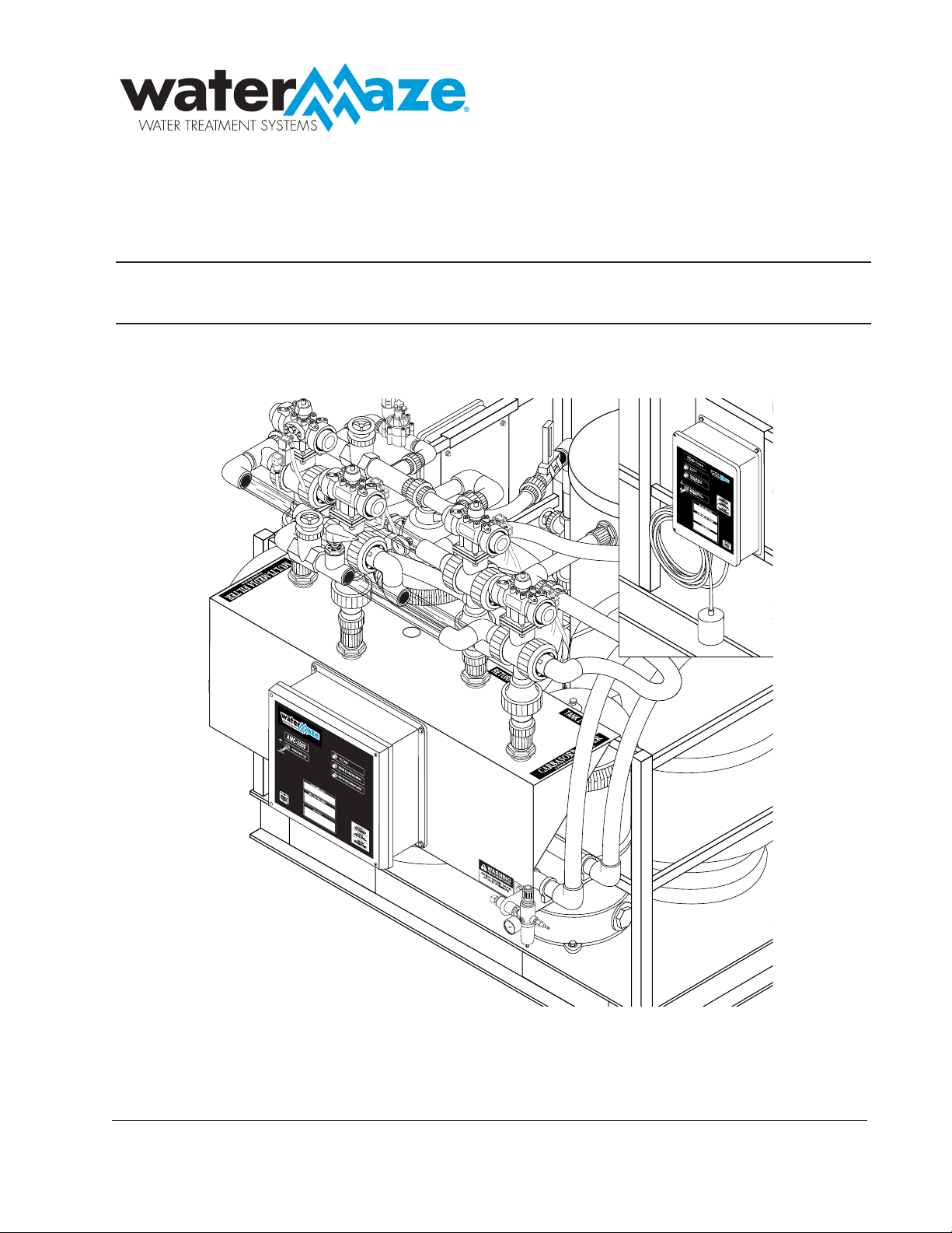
OPERATOR’S MANUAL
AMC/TDS
■
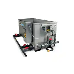
AMC-1000
■
AMC-2000
■
AMC-3000
■
TDS-1000
For technical assistance or the Water Maze Dealer nearest you
consult our web page at www.wmaze.com
#8.913-965.0 - A

CONTENTS
2
Watermaze AMC/TDS Operator's Manual 8.913-965.0 - A
Model Number
Serial Number
Date of Purchase
The model and serial numbers will be found on a decal attached to
the AMC/TDS-1000. You should record both serial number and date
of purchase and keep in a safe place for future reference.
Introduction .................................................................................................................................... 3
Unpacking ...................................................................................................................................... 3
Specifi cations ................................................................................................................................. 3
Important Safety Information ......................................................................................................3-4
Operation AMC-2000 and AMC-3000 ............................................................................................ 4
Setting and Editing Current Time and Day ................................................................................ 4, 7
Component Identifi cation AMC-1000/AMC-3000 ........................................................................... 5
Component Identifi cation, AMC-2000 ............................................................................................ 6
Running Programs ......................................................................................................................7-8
Operation AMC-1000 ..................................................................................................................... 8
Operation TDS-1000 ...................................................................................................................... 8
Installation Instructions AMC-2000 ...........................................................................................8-17
Installation AMC-3000 ............................................................................................................18-27
Dump Valve Installation Instructions AMC-1000/AMC-3000 ........................................................ 28
TDS-1000 Installation Instructions ............................................................................................... 29
Control Panel Exploded View, AMC-2000/AMC-3000 ................................................................. 30
Control Panel Exploded View Parts List, AMC-2000/AMC-3000 ................................................. 31
Control Panel, Exploded View, AMC-1000/TDS-1000 ................................................................. 32
Control Panel, Exploded View Parts List, AMC-1000/TDS-1000 ................................................. 33
Exploded View, AMC-2000/AMC-3000 ........................................................................................ 34
Exploded View Parts List, AMC-2000/AMC-3000 ........................................................................ 35
Warranty ...................................................................................................................................... 37
AMC / TDS OPERATOR’S MANUAL
3
Watermaze AMC/TDS Operator's Manual 8.913-965.0 - A
INTRODUCTION
Your owner’s manual has been prepared to provide you with
a simple and understandable guide for equipment operation
and maintenance, based on the latest product information
available at the time of printing. To keep your machine in
top running condition, follow the specifi c maintenance and
troubleshooting procedures given in this manual.
NOTE: WATER MAZE reserves the right to make chang-
es at anytime without incurring any obligations.
Owner/User Responsibility:
The owner and/or user must have an understanding of the
manufacturer’s operating instructions and warnings before
using this WATER MAZE machine. Warning information
should be emphasized and understood. If the operator is
not fl uent in English, the manufacturer’s instructions and
warnings shall be read to and discussed with the operator
in the operator’s native language by the purchaser/owner,
making sure that the operator comprehends its contents.
SAVE THESE INSTRUCTIONS
The owner and/or user must study and maintain the
manufacturers’ instructions for future reference.
This manual should be considered a permanent part
of the machine and should remain with the machine
if resold.
UNPACKING: AMC-2000/3000
1. AMC Bracket Assembly
2. Manifold
3. Accessory Box
4. Operator’s Manual
Note any damage to machine or components for claims
against the freight lines.
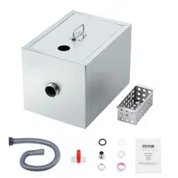
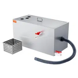
UNPACKING:
AMC-1000/TDS-1000
1. AMC-1000/TDS-1000 Control Box
2. Operator's Manual
Note any damage to machine or components for claims
against the freight lines.
SPECIFICATIONS
Air Requirements: 3 CFM, 60-100 PSI (AMC Units Only)
Voltage: Supply Voltage from Base Machine
Dimensions: AMC-2000/3000, Length 55" Width 19"
Height 31"
Dimensions: AMC-1000/TDS-1000, Length 15.5"
Width 8" Height 16"
Weight: AMC-2000/3000, 150 Lbs
Weight: AMC-1000/TDS-1000, 15 Lbs
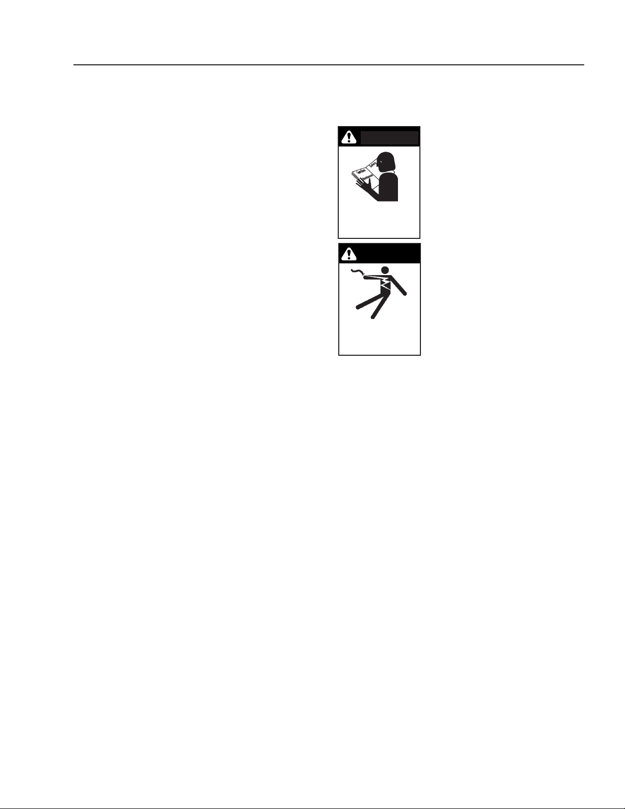
IMPORTANT SAFETY
INFORMATION
CAUTION: To reduce the risk of in-
jury, read operating instructions
carefully before using.
1. Read the owner’s manual
thoroughly. Failure to follow
the instructions will cause a
malfunction of the machine and
result in death, serious injury
and/or property damage.
WARNING: Ground system before
connecting to the power supply.
WARNING: Wire the system for
correct voltage. See Electrical
section (Page 9) of this manual
and motor nameplate.
WARNING: Meet the National
Electrical Code and local codes
for all wiring.
WARNING: Follow the wiring instructions in this
manual when connecting the system to the power
lines.
WARNING: All wiring must be performed by a quali-
fi ed electrician.
2. Know the system application, limitations, and poten-
tial hazards.
3. WARNING: Risk of electric shock.
All wiring should be performed by a qualifi ed electri-
cian.
4. Never make adjustments on the machine while it
is in operation, except for those prescribed in this
manual.
5.
The power must be brought from the base machine
and wired into the electrical box on the AMC or TDS.
6. Before servicing the machine, refer to all the MSDS’s
on the material identifi ed in the waste stream. You
must comply with all warnings and wear all protective
clothing as stated on the MSDS’s.
7. Protect all electrical cords from sharp objects, hot
surfaces, oil, sunlight, and chemicals. Avoid kinking
the cords. Replace or repair damaged or worn cords
immediately.
8. Inlet water temperature must not exceed 85°F.
9. Disconnect the power before servicing this machine.
If the power disconnect is out of sight, lock it in the
open position and tag it to prevent unexpected
application of power.
10. The best insurance against an accident is precaution
and knowledge of the equipment.
WARNING
KEEP WATER SPRAY
AWAY FROM
ELECTRICAL WIRING.
WARNING
READ OPERATOR’S
MANUAL
THOROUGHLY
PRIOR TO USE.
CAUTION

4
AMC / TDS OPERATOR’S MANUAL
Watermaze AMC/TDS Operator's Manual 8.913-965.0 - A
11. WATER MAZE is not liable for modifi cations or use
of components not purchased from WATER MAZE.
12. Personal Safety:
a. Wear safety glasses and other applicable pro-
tective clothing at all times when working on the
AMC or TDS.
Refer to item #6 under Important Safety
Information.
b. Keep your work area clean, uncluttered and
properly lighted. Replace all unused tools and
equipment.
c. Keep visitors at a safe distance from the work
area.
d. Make the workshop safe with padlocks and
master switches.
13. Release all pressure within the system before servic-
ing any component.
14.
Drain all liquids from the component before servicing.
15. Check hoses for weak or worn condition before each
use, making certain that all connections are secure.
16. Periodically inspect system components. Perform
routine maintenance as required.
17. Do not stand on the bracket or electrical box.
18. Keep from freezing.
19. Do not spray water directly at machine.
OPERATION:
AMC-2000 & AMC-3000
Automatic Backwash Mode
Backwashing the multi-media and carbon filters is
required to rejuvenate the fi lter media. Backwashing
removes collected materials and disperses the media
to eliminate any channeling. The AMC-2000 & 3000
automatically backwash these fi lters every day based
on input from the AMC controller. When you program
the AMC controller, per the instructions on pages 7 and
8, the multi-media will start backwashing at midnight for
30 minutes. The unit will recover the water level in Tank
#1 and then backwash the carbon fi lter. The operator
cannot use the pressure washer at that time, so it is
important that the program imitates your schedule. If it
doesn’t, call the factory for assistance in reprogramming
your controller.
To backwash the multi-media fi lter, the AMC controller
energizes the air actuated three way valves (ASV1,
ASV2). A slip stream solenoid (WSV1) is activated and
water fl ow to the multi-media fi lter should be adjusted
to 30 GPM using WSV1 fl ow control valve. Water is
pumped from Tank #1 through the fi lter by the fi lter
pump. This process continues for 30 minutes and the
resulting backwash outfl ow is returned to the wash pad
catch basin. The AMC controller will then wait 15 min-
utes to allow Tank #1 to refi ll. To backwash the carbon,
the AMC controller energizes the air actuated three
way valves (ASV1, ASV3, ASV4). The fl ow through the
carbon fi lter should be set to 15-20 GPM using carbon
valve BV2. This process continues for 30 minutes and
the resulting backwash outfl ow is returned to the wash
pad catch basin.
Automatic Sludge Dump (AMC-3000 Only)
During normal operation, the settling properties of the
solids will result in sludge build-up inside the cone bottom
clarifi er tank. This sludge must be periodically removed.
This is accomplished once each day by an automated
sludge dump system.
To dump sludge, the AMC controller energizes an air
activated dump valve (ASV5) while simultaneously en-
ergizing a water solenoid (WSV2). The water solenoid
will stir-up any impacted material in the bottom of the
cone bottom tank and allow sludge to fl ow to the sludge
collection bag. To reduce excess water in the sludge bag,
the water solenoid is only activated for a few seconds.
Once the dump valve closes, the sludge bag is allowed
to de-water and excess water is returned, via gravity
feed, to the wash pad catch basin.
PROGRAMMING THE AMC
(AUTOMATIC MAINTENANCE
CONTROLLER)
The AMC Controller needs to be programmed on site.
The reason for this is when power is cut to the unit the
program is lost. There is a 9V battery inside the AMC
Controller (pull down on bottom cover of the AMC) that
will power the controller and hold the program for ap-
proximately 72 hours. The 9V battery will take care of
intermittent power loss but will not hold program from
factory to site during shipping. Before programming, con-
nect battery inside AMC. Replace battery yearly.
SETTING/EDITING
CURRENT TIME AND DAY
1. Turn control dial to SET TIME & DAY position.
2. To set current hour, press +/ON or -/OFF button.
3. Press the NEXT button.
4. To set current minute, press +/ON or -/OFF button.
5. Press the NEXT button.
6. To set current day, press +/ON or -/OFF button until
current day is fl ashing.
7. Return dial to the AUTO/ON position.
AMC / TDS OPERATOR’S MANUAL
5
Watermaze AMC/TDS Operator's Manual 8.913-965.0 - A
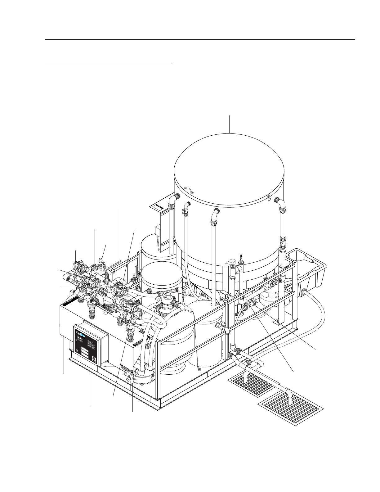
COMPONENT IDENTIFICATION
AMC-1000/3000
Air
Regulator
WSV2
AMC-1000 or
TDS-1000
WSV1
ASV1
BV2
ASV4
Control
Box
AMC-2000 or
AMC-3000
ASV2
ASV5
ASV3
BV1
CLP-5023,7023,7033
6
AMC / TDS OPERATOR’S MANUAL
Watermaze AMC/TDS Operator's Manual 8.913-965.0 - A
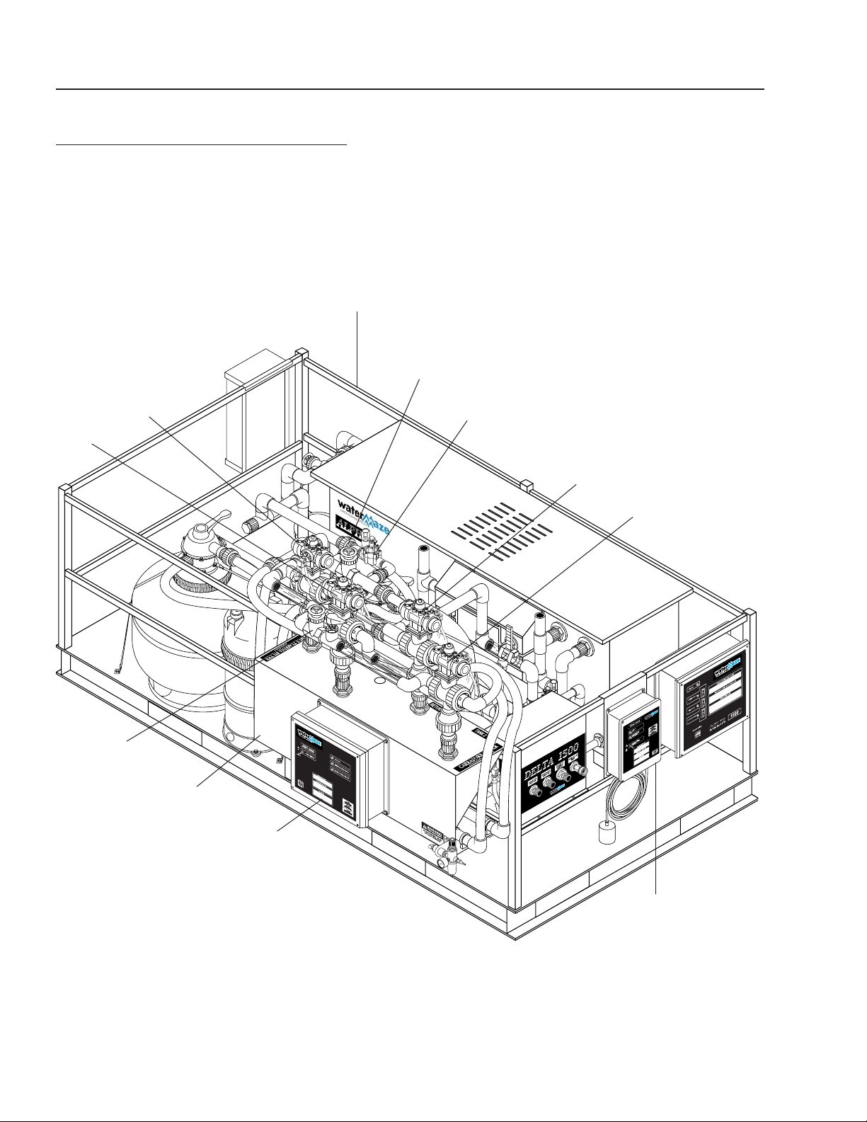
COMPONENT IDENTIFICATION
AMC-2000
ASV1
AMC-
2000
TDS-1000
Control
Box
BV2
ASV4
ASV3
WSV1
BV1
Delta 1500, 3000
ASV2

AMC / TDS OPERATOR’S MANUAL
7
Watermaze AMC/TDS Operator's Manual 8.913-965.0 - A
PROGRAMMING BACKWASH & DUMP
MODES
The backwash program requires (3) basic instructions
to operate automatically:
A. Operation Days (Usually 7 days a week).
B. Start Time (Usually at night when washing is not
being performed).
C. Mode Run Times (length of backwash and recircula-
tion times)
A. Setting/Editing Program Operation Days
1. Turn control dial to SET PROGRAM OPERATION
DAYS.
2. Set program switch to program A, B, or C. (See Pro-
gram Schedule Sheet for program descriptions).
3. Press +/ON or -/OFF button until CAL (calendar) is
fl ashing.
4. Press the NEXT button to see program operation
days. SU (Sunday) will begin fl ashing.
5. To select the day (fl ashing), press the +/ON button.
To remove a day, press the -/OFF button.
6.
Repeat step 5 until all operation days are selected.
7. Repeat steps 1-6 for Programs A, B, or C.
8. Return dial to the AUTO/ON position.
B. Setting/Editing Program Start Time
1. Turn control dial to SET PROGRAM START TIME.
2. Set program switch to program A, B, or C. (See Pro-
gram Schedule Sheet for program descriptions).
3. Press +/ON or -/OFF button until program start time
number 1 is fl ashing (upper left corner of display).
4. Press the NEXT button.
5. To set the hour, press +/ON or -/OFF button.
6. Press the NEXT button.
7. To set the minute, press +/ON or -/OFF button.
NOTE: Programs 2, 3, 4 should read OFF.
8. Return dial to the AUTO/ON position.
C. Setting/Editing Mode Run Times
1. Turn control dial to SET MODE RUN TIMES.
2. Set program switch to program A, B, or C (see Pro-
gram Schedule Sheet for program descriptions).
3. Mode number 1 will begin fl ashing (lower left corner
of display).
4. Press the NEXT button. Mode number will stop fl ash-
ing and timer display or “OFF” will begin fl ashing.
5. To set run time, press +/ON or -/OFF button.
NOTE: To remove (skip) a mode, press the +/ON
and -/OFF buttons at the same time. OFF should be
displayed. (Refer to Program schedule sheet below,
e.g. Program A, Mode 1 is 30 minutes).
6. Press the NEXT button. The next mode number will
begin fl ashing.
7. Repeat steps 4-6 until all run times have been set
for modes 1-6.
8. Repeat steps 1-7 for Programs A, B, and C.
9. Return dial to the AUTO/ON position.
PROGRAM SCHEDULE SHEET
The Program Schedule Sheet shows descriptions of Modes, Programs and Recommended Settings:
PROGRAM A
Auto Backwash
7 days/week
PROGRAM B
Manual Backwash
PROGRAM C
Test Mode
MODE DESCRIPTION MODE RUN TIME MODE RUN TIME MODE RUN TIME
1 Media Backwash 30 minutes 30 minutes 5 minutes
2 Tank 1 Recovery 15 minutes 15 minutes 5 minutes
3 Carbon Backwash 30 minutes 30 minutes 5 minutes
4 Auto Purge (AMC-3000) 15 minutes OFF 5 minutes
Program
Start Times
1 12:00 AM OFF OFF
2 OFF OFF OFF
3 OFF OFF OFF
4 OFF OFF OFF

8
AMC / TDS OPERATOR’S MANUAL
Watermaze AMC/TDS Operator's Manual 8.913-965.0 - A
RUNNING PROGRAMS
Auto Backwash (Program A) - Used for
Daily Operations
1. Set program switch to Program A.
2. Turn control dial to AUTO/ON position. Program will
cycle through modes 1-4 when start time is reached.
Mode number and program letter will fl ash to indi-
cate status. Display will show time remaining in that
mode.
3. AMC-2000/3000 will return to fi lter mode when mode
4 is complete.
Manual Backwash (Program B)
1. Set program switch to Program B.
2. Turn control dial to AUTO/ON position.
3. Press the MANUAL START button twice. CLP will
cycle through the following modes:
• Media Backwash
• Tank 1 Recovery
• Carbon Backwash
4. To skip a mode, press the NEXT button.
5. To pause a mode, press +/ON and -/OFF buttons at
the same time. To resume, press the NEXT button.
6. To cancel program press +/ON and -/OFF buttons
at the same time, twice.
7. Set program switch back to Program A to resume
Auto Backwash program.
Test Program (Program C)
1. Set program switch to Program C.
2. Turn control dial to AUTO/ON position.
3. Press the MANUAL START button.
4. See Running Manual Backwash instructions above
to pause, skip and cancel programs.
5. Set program switch back to Program A to resume.
OPERATION: AMC-1000
During normal operation, the settling properties of solids
will result in sludge build-up inside the cone bottom of the
clarifi er tank. This sludge must be periodically removed.
The AMC-1000 automated sludge dump system is de-
signed to remove solids each day.
To dump sludge from the cone bottom tank, a 24-hour
timer in the AMC-1000 control box energizes an air
activated dump valve (ASV5). The duration of the dump
mode can be adjusted by a second timer (measured in
seconds). Once the dump valve closes, the sludge bag
is allowed to de-water and excess water is returned, via
gravity feed, to the wash pad catch basin.
OPERATION: TDS-1000
The TDS-1000 dramatically reduces the Total Dissolved
Solids (TDS), Total Suspended Solids (TSS) and even
detergents that can accumulate in a recycle system. The
TDS-1000 is designed to remove a specifi ed volume of
water from the system each day. The freshwater make-
up system on the CLP or Delta will then add fresh water
to the system.
To purge water from the CLP or Delta system, a 24-hour
timer in the TDS-1000 control box energizes the rain
water solenoid found on the water connection panel.
The transfer pump will turn on and discharge water from
tank #2 to a holding tank or to sewer (if permitted). The
duration of the dump mode and therefore the amount of
water purged can be adjusted by a second timer. The
freshwater solenoid on the water connection panel is
disabled while the system purges. A N/C fl oat is supplied
with the TDS-1000 to prevent overfl owing the water in
the holding tank.
INSTALLATION
INSTRUCTIONS:
AMC-2000
NOTE: Different models and years of manufactur-
ing may have been built slightly different from the
instructions below. It is recommended you have a va-
riety of fi ttings available for those slight differences.
Tools & Supplies
• 1" Hole Saw
• Large Channel Locks
• Medium Straight Screw Driver
• Small Straight Thin Screw Driver
• Hack Saw - Don't Use Pipe Cutter
• Tape Measure
• Drill
• Tefl on Tape
• Purple Primer
• Heavy Duty Gray PVC Cement
• Rags
Wire/Conduit — depends upon amp draw of
machine and fi lter pump. Follow local codes.
Electrical fi ttings (Spader, butt connector, etc.)
Wire Strippers
Wire Cutters

AMC / TDS OPERATOR’S MANUAL
9
Watermaze AMC/TDS Operator's Manual 8.913-965.0 - A
Electrical
Refer to Wiring Diagram
1. Run power for the AMC-2000 from the power inlet
terminal block of the Delta. (Wire not supplied.)
2. Run fi lter pump wires from AMC-2000 to the fi lter
pump motor. Wire the same way it is wired from
main control box. Install a tee at the motor to ac-
cept the line from the AMC. On a three-phase unit,
make sure fi lter pump is spinning in the correct
rotation from both power sources. (Wire not sup-
plied.)
3. Run the black N/O fl oat from the AMC to the fi lter
pump tank. Tie wrap N/O fl oat to existing low water
fl oat in fi lter pump tank.
Air
1. Air is required to operate air valves. 3 CFM with 60-
100 psi will meet air requirements.
2. An air regulator valve is provided.
3. Connect air hose to auto dump valve.
10
AMC / TDS OPERATOR’S MANUAL
Watermaze AMC/TDS Operator's Manual 8.913-965.0 - A
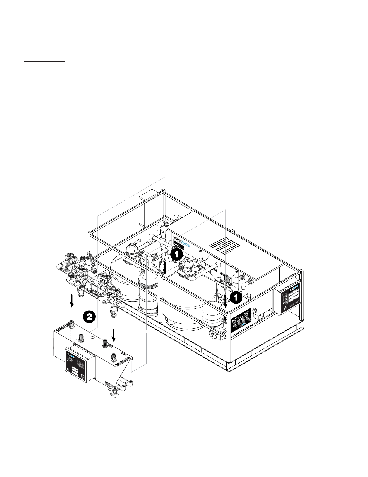
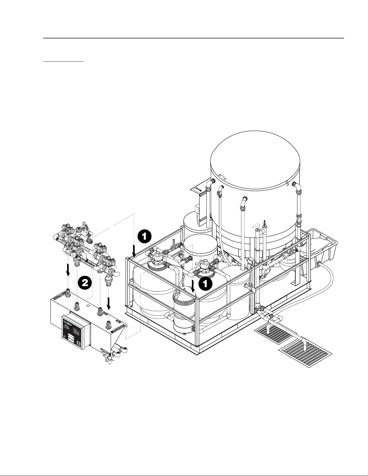
AMC-2000
INSTALLATION INSTRUCTIONS
Step 1. Hang AMC-2000 bracket assembly on side rail
of Delta skid.
Step 2. Attach manifold to AMC-2000. Line up half-
unions on manifold with half-unions on AMC
bracket assembly. Make sure o-rings are in
place. Tighten unions.
AMC-2000
Bracket Assy
AMC-2000
Manifold Assy

AMC / TDS OPERATOR’S MANUAL
11
Watermaze AMC/TDS Operator's Manual 8.913-965.0 - A
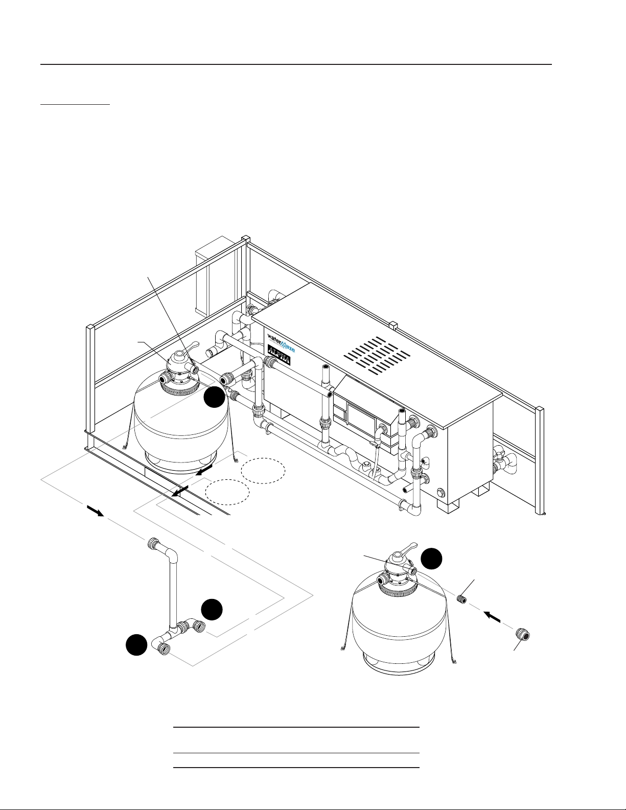
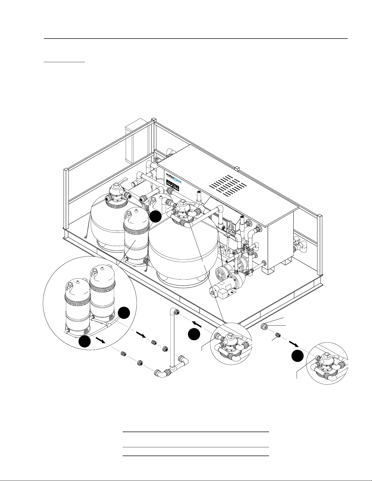
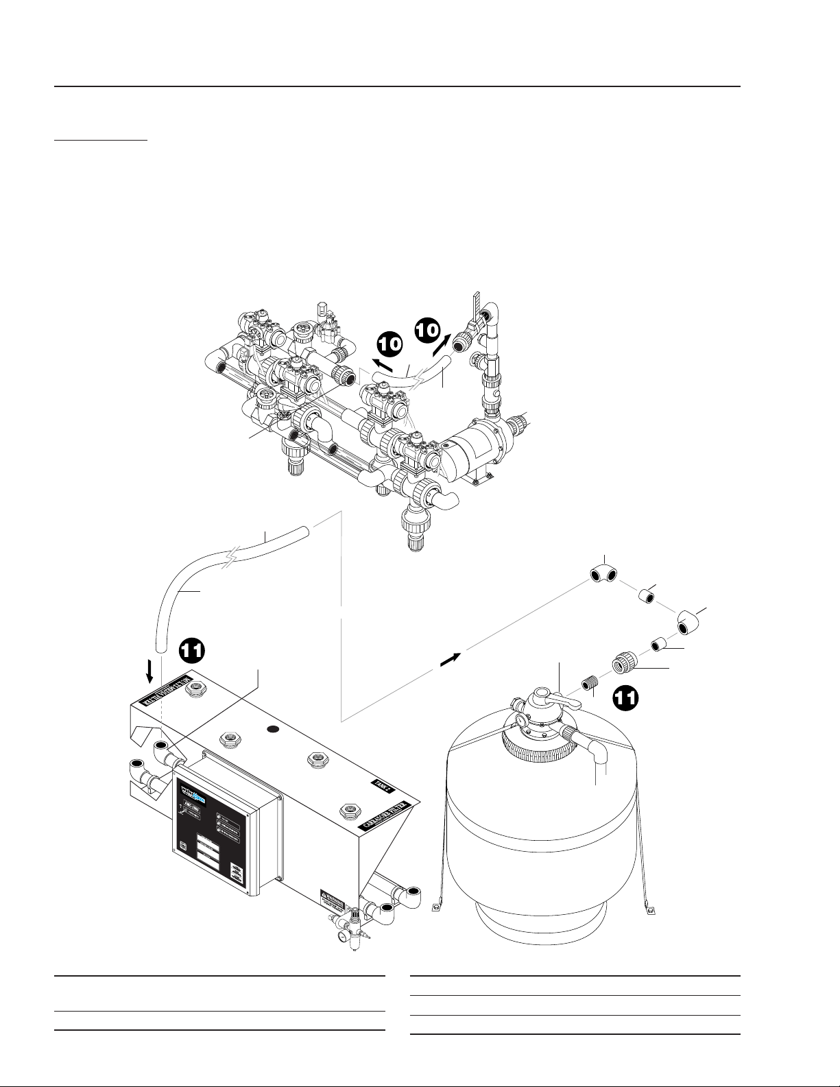
AMC-2000
INSTALLATION INSTRUCTIONS (CONTINUED)
Step 6. Install 1-1/2" plug (item 1) into backwash port
on valve head.
Step 7. Install pipe nipple (item 3) and union (item 2)
into outlet port on valve head. (This will connect
to the AMC-2000 at a later step.)
Step 8. Take half of new slip x slip 1-1/2" union (item
5) and couple to remaining half union on line
to water storage tank. If existing union on water
storage line is different from one supplied, cut
old union off and install new union.
Backwash
Port
Cartridge
Filters
Carbon
Filter
Carbon
Filter
Diverter
Valve
Outlet
Port
Diverter
Valve
Outlet
Port
2
4
1
1
3
5
ITEM PART NO. DESCRIPTION
1 8.706-394.0 Plug, 1-1/2", PVC 80
2 8.706-470.0 Union, 1-1/2" Slip x Thread, PVC
80 Spears
3 8.706-424.0 Nipple, 1.5" x Close, PVC 80
Step 3. Break pipe union coming off of carbon tank
backwash port. Cut pipe to return line leav-
ing enough stub for female adapter. Remove
remaining fi ttings from diverter valve backwash
port.
Step 4. Break pipe union on outlet of carbon fi lter.
Remove remaining adapter from valve head.
Step 5. Glue slip x thread 1-1/2" adapter (item 4) to
return line and install 1-1/2" plug (item 1) into
adapter.
ITEM PART NO. DESCRIPTION
4 8.706-448.0 Adapter, 1.5" x 1.5", Ft x Slip,
PVC 80
5 8.706-469.0 Union, 1-1/2" Slip x Slip, PVC 80
Spears
Backwash
Port
4
4
3
3
8
7
5
6
12
AMC / TDS OPERATOR’S MANUAL
Watermaze AMC/TDS Operator's Manual 8.913-965.0 - A
AMC-2000
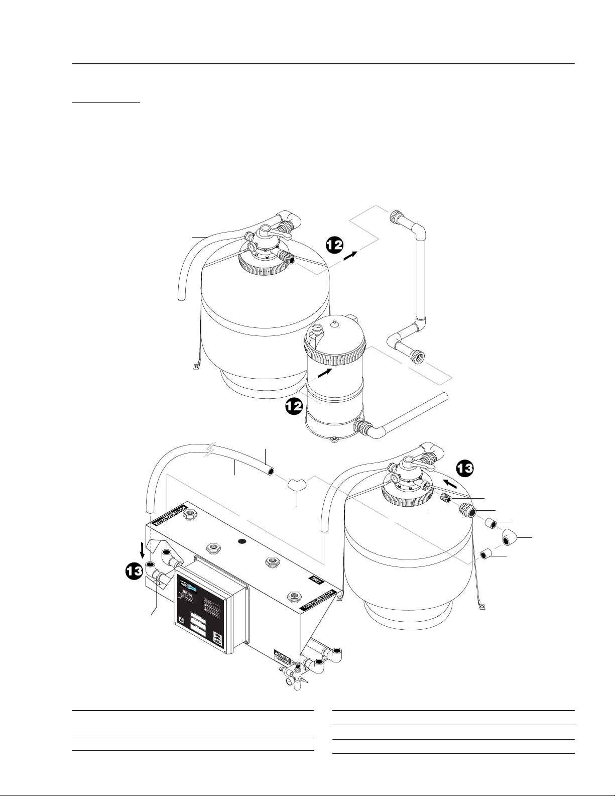
INSTALLATION INSTRUCTIONS (CONTINUED)
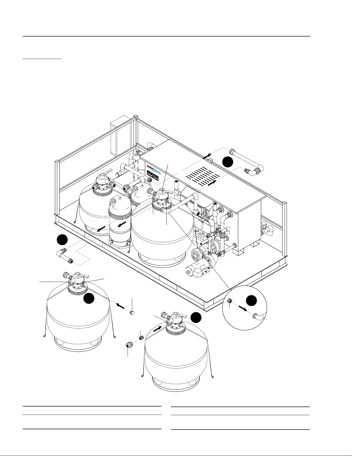
Step 9. Drain cartridge fi lters. Break union on inlet
port of carbon fi lter. Remove pipe assembly as
shown. Make sure to close cartridge fi lter drain
valve when fi nished.
Step 10. Couple half of new slip x thread 1-1/2" union
(item 1) and pipe nipple (item 2) to remaining
half union on inlet port of carbon fi lter.
Inlet
Port
Cartridge
Filters
Carbon
Filter
Diverter
Valve
1
2
Carbon
Filter
Inlet
Port
ITEM PART NO. DESCRIPTION
1 8.706-470.0 Union, 1-1/2" Slip x Thread,
PVC 80 Spears
2 8.706-424.0 Nipple, 1.5" x Close, PVC 80
9
9
9
10
AMC / TDS OPERATOR’S MANUAL
13
Watermaze AMC/TDS Operator's Manual 8.913-965.0 - A
AMC-2000
INSTALLATION INSTRUCTIONS (CONTINUED)
Step 11. Break union on outlet port of multi-media fi lter.
Remove pipe assembly as shown.
Cartridge
Filters
1/2" Slip x Thread
Union
Multi-Media
Filter
Multi-Media
Filter Diverter
Valve
Outlet
Port
Multi-Media
Filter Diverter
Valve
Outlet
Port
2
1
ITEM PART NO. DESCRIPTION
1 8.706-470.0 Union, 1-1/2" Slip x Thread,
PVC 80 Spears
2 8.706-424.0 Nipple, 1.5" x Close, PVC 80
Step 12. Couple slip half of new slip x thread 1-1/2" union
(item 1) to remaining half union on outlet port of
multi-media fi lter diverter valve. If different style
of union, remove old union and install nipple
(item 2) and new union (item 1).
11
11
12
11
11
14
AMC / TDS OPERATOR’S MANUAL
Watermaze AMC/TDS Operator's Manual 8.913-965.0 - A
AMC-2000
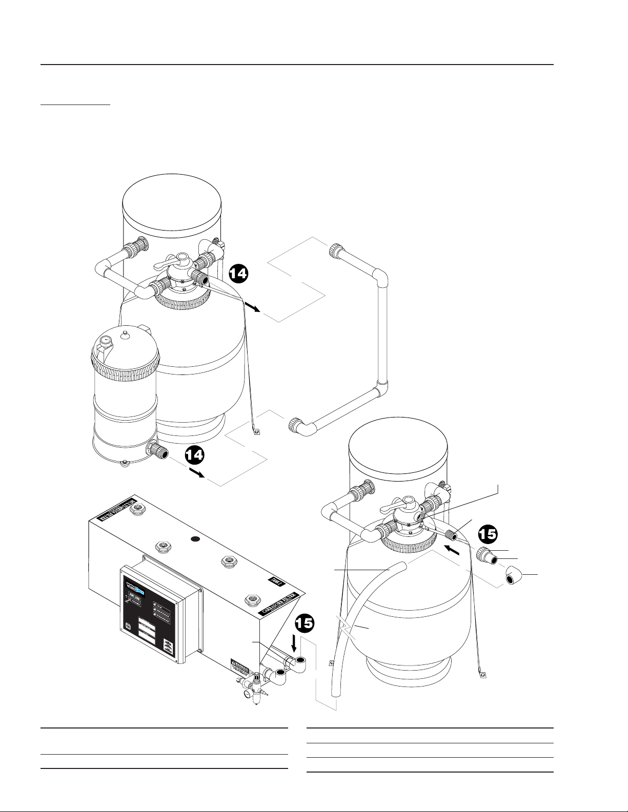
INSTALLATION INSTRUCTIONS (CONTINUED)
ITEM PART NO. DESCRIPTION
1 8.706-394.0 Plug, 1-1/2", PVC 80
2 8.706-470.0 Union, 1-1/2" Slip x Thread,
PVC 80 Spears
ITEM PART NO. DESCRIPTION
3 8.706-424.0 Nipple, 1.5" x Close, PVC 80
4 8.706-469.0 Union, 1-1/2" Slip x Slip, PVC 80
Spears
Step 13. Break union on inlet port of multi-media fi lter
and remove fi ttings as shown.
Step 14. Break union on backwash port of multi-media
fi lter and remove fi ttings as shown.
Step 15. Install 1-1/2" plug (item 1) into back wash port
on valve head.
Multi-Media
Filter
Carbon
Filter
Step 16. Take half of new slip x thread 1-1/2" union (item
2) and couple to remaining half union on inlet
port of multi-media fi lter or install new union.
Step 17. Take half of new slip x slip 1-1/2" union (item
4) and couple to remaining half union on inlet
line (to fi lter pump).
Multi-Media
Filter
Multi-Media
Filter
1
3
2
4
Backwash
Port
Inlet
Port
Inlet Port
Backwash
Port
Inlet
Port
Multi-Media Filter
Diverter Valve
14
13
15
17
16
AMC / TDS OPERATOR’S MANUAL
15
Watermaze AMC/TDS Operator's Manual 8.913-965.0 - A
AMC-2000
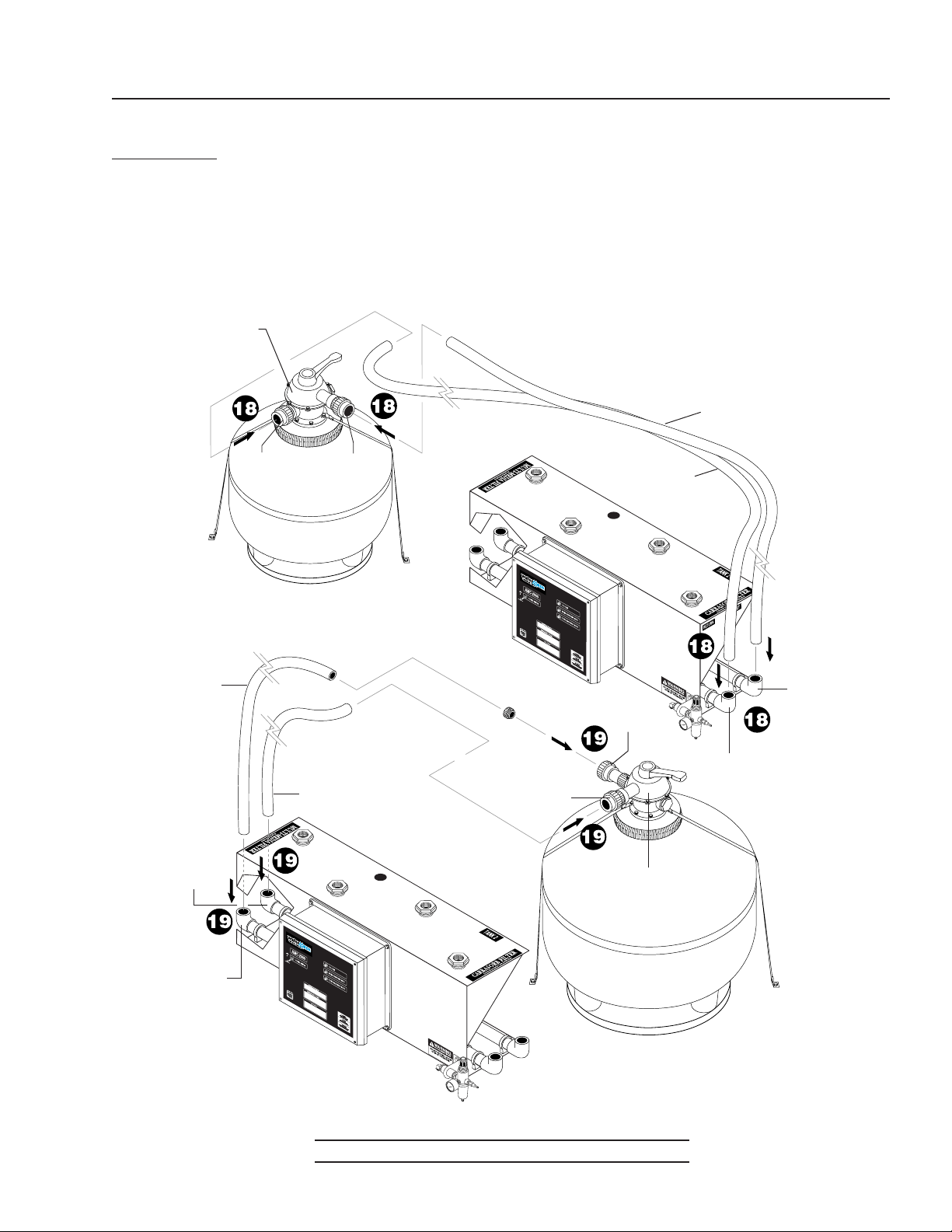
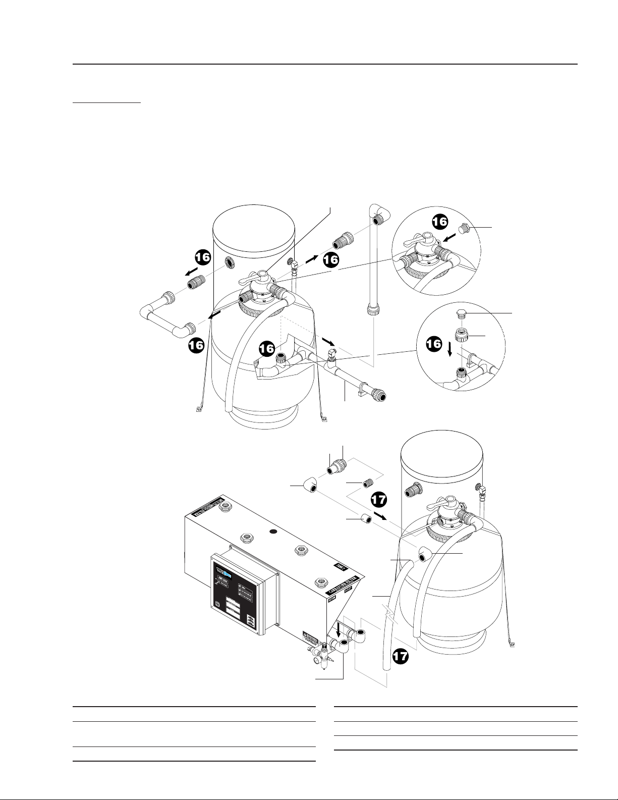
INSTALLATION INSTRUCTIONS (CONTINUED)
Step 18. Measure, cut and glue 1-1/2" gray hose (item
1) from inlet port on carbon fi lter to inlet port
on AMC-2000. Prepare hose ends with purple
primer and glue using heavy duty gray pvc ce-
ment. Repeat for outlet port of carbon fi lter.
Step 19. Measure, cut and glue 1-1/2" gray hose from
inlet port of multi-media fi lter to inlet port of
AMC-2000. Repeat for outlet port of multi-me-
dia fi lter.
Diverter
Valve
1-1/2" Gray
Hose
Inlet
Port
Carbon
Filter
Outlet
Port
1-1/2" Gray
Hose
1-1/2" Gray
Hose
AMC-2000
Multi-Media
Inlet
AMC
Bracket
Assembly
AMC-2000
Multi-Media
Outlet
Outlet
Port
AMC-2000
Carbon Filter
Outlet
1/2" Slip
Union
Inlet Port
Multi-Media
Filter
1-1/2" Gray
Hose
AMC
Bracket
Assembly
Diverter
Valve
AMC-2000
Carbon Filter
Inlet
1
1
1
1
ITEM PART NO. DESCRIPTION
1 8.711-813.0 Hose, 1-1/2", Gray Spiralite, 50 ft.
19
16
AMC / TDS OPERATOR’S MANUAL
Watermaze AMC/TDS Operator's Manual 8.913-965.0 - A
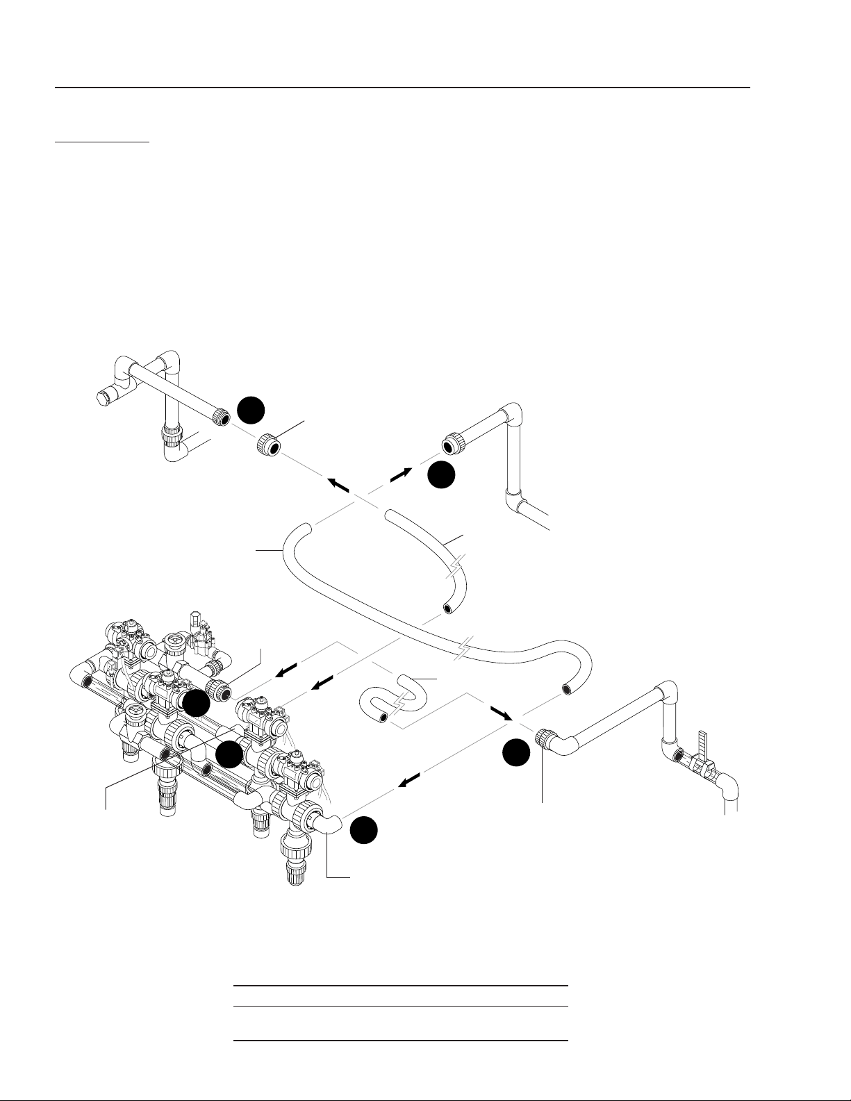
AMC-2000
INSTALLATION INSTRUCTIONS (CONTINUED)
Step 20. Measure, cut and glue 1-1/2" gray hose (item
1) from half of slip x slip 1-1/2" union (item 2)
on backwash line to backwash port on AMC-
2000 manifold.
Step 21. Measure, cut and glue 1-1/2" gray hose from
1-1/2" union on inlet line (from fi lter pump) to
multi-media inlet union on AMC-2000 mani-
fold.
Open original fi lter fl ow valve to full fl ow. BV1
is now the valve you adjust for your fi lter fl ow.
Step 22. Measure, cut and glue 1-1/2" gray hose from
1-1/2" union on clean water tank line (to alpha
tank) to fi ltered water port on AMC-2000 mani-
fold.
To Backwash
Line
AMC-2000
Multi-Media
Inlet Union
1-1/2" Gray
Hose
To 1-1/2" Gray
Hose
To Clean
Water Tank
1-1/2" Slip
Union
Flow
Meter
To Backwash
Port
AMC-2000
Manifold
Assembly
Filtered Water
Port
1-1/2" Gray
Hose
To
Filter
Pump
1
1
2
1
ITEM PART NO. DESCRIPTION
1 8.711-813.0 Hose, 1-1/2", Gray Spiralite, 50 ft
2 8.706-469.0 Union, 1-1/2" Slip x Slip, PVC 80
Spears
Filter Pump
Inlet
22
20
22
20
21
21
AMC / TDS OPERATOR’S MANUAL
17
Watermaze AMC/TDS Operator's Manual 8.913-965.0 - A
AMC-2000
INSTALLATION INSTRUCTIONS (CONTINUED)
Step 23. Wire fi lter pump to AMC-2000 control box as
shown. (Wire not provided.) See wiring dia-
gram.
Step 24. Run AMC-2000 fl oat into fi lter pump tank. Tie
wrap fl oat to existing low level fl oat.
Filter
Pump
Tie Wrap
ITEM PART NO. DESCRIPTION
1 8.716-142.0 Switch, Float, N/O, .20 MDWOP,
1003825, Black
2 8.706-425.0 Tee, 1/2" FT x FT x FT, PVC 80
3 8.706-467.0 Nipple, 1/2", PVC 80
1
Low Water
Float From
AMC-2000
2
3
23
24

18
AMC / TDS OPERATOR’S MANUAL
Watermaze AMC/TDS Operator's Manual 8.913-965.0 - A
INSTALLATION
INSTRUCTIONS:
AMC-3000
Note: Different models and years of manufactur-
ing may have been built slightly different from the
instructions below. It is recommended you have a
variety of fi ttings available for those slight differ-
ences.
Tools & Supplies
• 1" Hole Saw
• Large Channel Locks
• Medium Straight Screwdriver
• Small Straight Thin Screwdriver
• Hack Saw - Don't Use Pipe Cutter
• Tape Measure
• Drill
• Tefl on Tape
• Purple Primer
• Heavy Duty Gray PVC Cement
• Rags
Wire/Conduit — depends upon amp draw of
machine and fi lter pump. Follow local codes.
Electrical fi ttings (Spader, butt connector, etc.)
Wire Strippers
Wire Cutters
Electrical
Refer to Wiring Diagram.
1. Run your power for the AMC-3000 from the power
inlet terminal block of the CLP.
2. Run fi lter pump wires from AMC-3000 to the fi lter
pump motor. Wire the same way it is wired from
main control box. Install tee at motor to accept the
line from the AMC. If a three-phase unit, make sure
fi lter pump is spinning in the correct rotation
from both power sources.
3. Run the black N/O fl oat from the AMC to tank 1. Drain
water from tank 1. Drill hole in tank and position fl oat
at the same height as FS4. Use bulkhead and water
tight strain relief.
4. Connect solenoid coil wire from auto dump valve to
AMC.
Air
1. Air is required to operate air valves. 3 CFM with 60-
100 psi will meet air requirements.
2. An air regulator valve is provided.
3. Connect air hose to auto dump valve (AMC-1000/
AMC-3000).
AMC / TDS OPERATOR’S MANUAL
19
Watermaze AMC/TDS Operator's Manual 8.913-965.0 - A
AMC-3000
INSTALLATION INSTRUCTIONS
Step 1. Hang AMC-3000 bracket assembly on end rail
of CLP.
AMC-3000
Manifold
Assembly
AMC-3000
Bracket
Assembly
Step 2. Attach manifold to AMC-3000. Line up half-
unions on manifold with half-unions on AMC
bracket assembly. Make sure o-rings are in
place. Tighten unions.
20
AMC / TDS OPERATOR’S MANUAL
Watermaze AMC/TDS Operator's Manual 8.913-965.0 - A
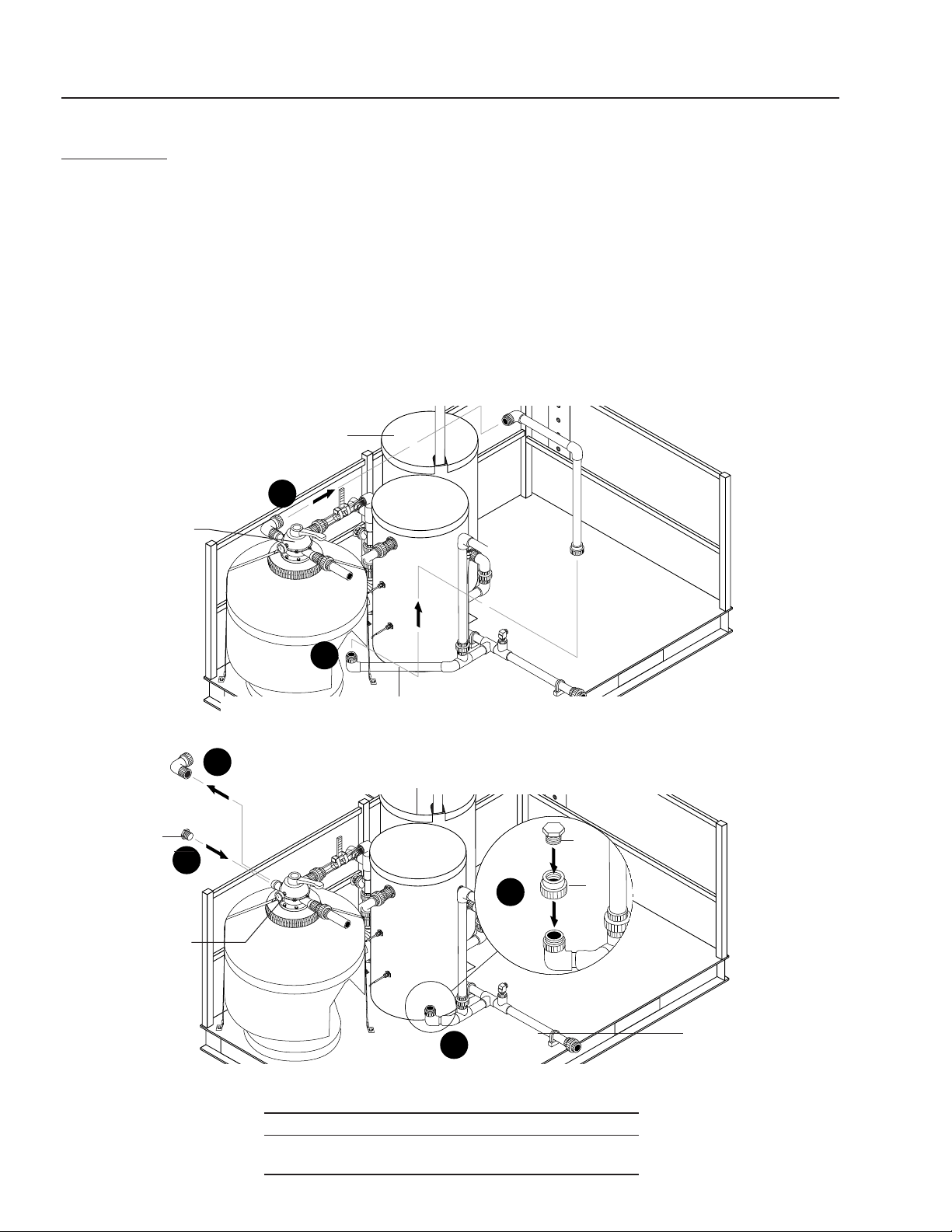
Step 3. Break pipe union coming off of multi-media tank
diverter valve that goes to return line. Follow
this line down to return line and break that union
or unions. Remove pipe. (On some models you
may also have to break unions on carbon fi lter
to remove this pipe.
Step 4. Remove remaining elbow and adapter from
multi-media valve head. Install 1-1/2" plug (item
1) into valve head port.
Step 5. Take threaded half of slip x thread 1-1/2" union
(item 2) and couple to remaining half union
coming off return line. If existing union on return
line is different from one supplied, cut old union
off and install new union. Thread in 1-1/2" pipe
(item 1) plug into this union. (Depending on
model and when it was built you may not need
to do this. What you need is one line open going
to the return line. Most CLP machines have two
- so on those units you will need to plug one.)
Storage Tank #1
Multi-Media Tank
Diverter Valve
Storage
Tank #2
Multi-Media
Filter
Return Line
1
Multi-Media
Valve Head Port
Storage Tank #1
Storage
Tank #2
Return
Line
AMC-3000
INSTALLATION INSTRUCTIONS (CONTINUED)
2
1
ITEM PART NO. DESCRIPTION
1 8.706-394.0 Plug, 1-1/2", PVC 80
2 8.706-470.0 Union, 1-1/2" Slip x Thread,
PVC 80 Spears
3
3
4
4
5
5
AMC / TDS OPERATOR’S MANUAL
21
Watermaze AMC/TDS Operator's Manual 8.913-965.0 - A
AMC-3000
INSTALLATION INSTRUCTIONS (CONTINUED)
Storage
Tank #1
Storage
Tank #2
New Slip
x Slip Half
Union
Low Level
Float
Storage
Tank #1
Clear
Pipe
Flow
Meter
Pressure
Switch
1
4
2
3
ITEM PART NO. DESCRIPTION
1 8.706-387.0 Plug, 1/2" MIPT, PVC 80
2 9.802-051.0 Bulkhead, 1/2" PVC
ITEM PART NO. DESCRIPTION
3 8.716-142.0 Switch, Float, N/O, .20 MDWOP,
1003825, Black
4 8.706-469.0 Union, 1-1/2" Slip x Slip, PVC 80
Spears
Step 6. Remove pressure switch. Install plug (item 1).
Run wires to pressure switch located on AMC-
3000.
Step 7. Break union on clear pipe between fi lter fl ow
meter and inlet of multi-media valve. Push
clear pipe back a few inches. (Check that valve
coming out of fi lter pump will allow this.) Open
valve completely for full fl ow. BV1 is now the
valve you adjust for your fi lter fl ow.
Step 8. Take half of new slip x slip 1-1/2" union (item 4)
and couple to remaining half union coming off
clear pipe. (If different union than one supplied,
replace entire union.)
Step 9. Drill 1-1/8" hole inside of storage tank #1 as
shown. Install new low-level fl oat ( item 3) pro-
vided.
Multi-
media
Valve Inlet
Hole
1-1/8"
Bulkhead
Assy.
22
AMC / TDS OPERATOR’S MANUAL
Watermaze AMC/TDS Operator's Manual 8.913-965.0 - A
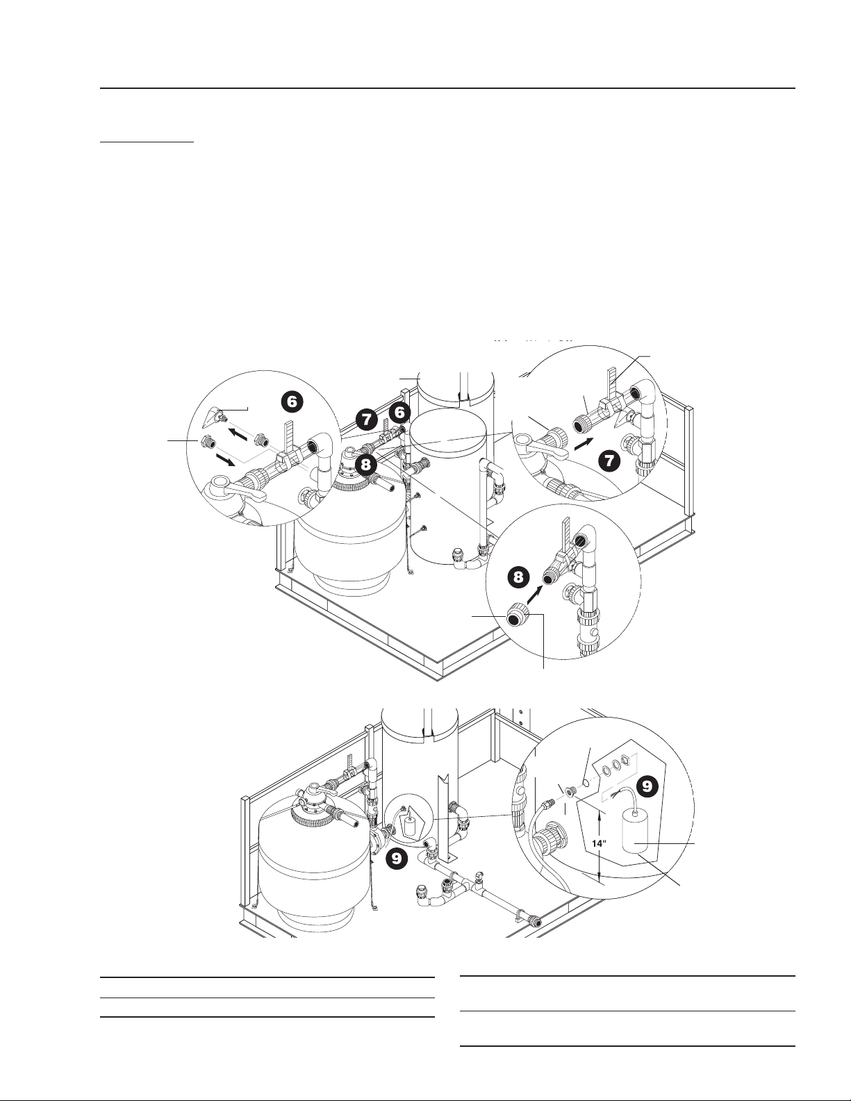
Step 11. From the outlet of multi-media diverter valve
install half of union to remaining half of union.
Glue elbows (item 3) to union (item 1) on di-
verter valve as shown. Measure, cut and glue
1-1/2" gray hose (item 2) to Multi-Media inlet
port on AMC-3000.
AMC-3000
INSTALLATION INSTRUCTIONS (CONTINUED)
ITEM PART NO. DESCRIPTION
1 8.706-470.0 Union, 1-1/2" Slip x Thread,
PVC 80 Spears
2 8.711-813.0 Hose, 1-1/2", Gray Spiralite, 50 ft.
ITEM PART NO. DESCRIPTION
3 8.706-374.0 Elbow, 1-1/2" S x S, PVC 80, 90°
4 8.706-424.0 Nipple, 1.5" x Close, PVC 80
5 8.706-367.0 Pipe, 1.5", PVC 80, 3 ft.
Multi-Media
Filter
AMC-3000 Multi-
Media Inlet Union
Union On
Clear Pipe
1-1/2"
Gray
Hose
1-1/2" Gray Hose
AMC-3000
Multi-Media Inlet
Diverter
Valve Outlet
2
4
1
5
3
5
3
2
Step 10. Measure and cut 1-1/2" gray hose (item 2) to
fi t from union on clear pipe to multi-media inlet
union on AMC-3000 manifold assembly. Using
"purple primer" prime end of hose going into
union on clear pipe. Using "heavy duty gray
PVC cement," glue in hose. Slide opposite end
of hose into AMC-3000 inlet union and repeat
same procedure.
AMC / TDS OPERATOR’S MANUAL
23
Watermaze AMC/TDS Operator's Manual 8.913-965.0 - A
Step 12. Drain cartridge filter. Disconnect plumbing
from multi-media fi lter to cartridge fi lter. NOTE:
Because you are removing the cartridge fi lter/
fi lters you may want to replace your multi-media
with garnet to provide fi ner fi ltering.
AMC-3000
INSTALLATION INSTRUCTIONS (CONTINUED)
AMC-3000
Multi-Media
Outlet
Diverter Valve
Outlet
Multi-Media
Filter
1-1/2"
Gray Hose
Cartridge
Filter
Multi-Media
Filter
To AMC-3000
Multi-Media
Outlet
4
3
1
5
3
5
2
ITEM PART NO. DESCRIPTION
1 8.706-470.0 Union, 1-1/2" Slip x Thread,
PVC 80 Spears
2 8.711-813.0 Hose, 1-1/2", Gray Spiralite, 50 ft.
ITEM PART NO. DESCRIPTION
3 8.706-374.0 Elbow, 1-1/2" S x S, PVC 80, 90°
4 8.706-424.0 Nipple, 1.5" x Close, PVC 80
5 8.706-367.0 Pipe, 1.5", PVC 80, 3 ft.
Step 13. Attach half of union to remaining half union
coming from outlet of multi-media diverter
valve. Glue elbow (item 3) to union (item 1)
on diverter valve as shown. Measure, cut and
glue 1-1/2" gray hose (item 2) to Multi-Media
port on AMC-3000 outlet.
24
AMC / TDS OPERATOR’S MANUAL
Watermaze AMC/TDS Operator's Manual 8.913-965.0 - A
Storage
Tank #2
1-1/2" Gray
Hose
Carbon
Filter
Storage
Tank #2
AMC-3000
Carbon
Filter Outlet
Cartridge
Filter
Carbon
Filter
AMC-3000
INSTALLATION INSTRUCTIONS (CONTINUED)
Step 14. Remove plumbing from cartridge fi lter to
carbon fi lter.
Step 15. Attach half union to remaining union (item 1)
on inlet to carbon fi lter. Glue elbow (item 3) to
union on diverter valve as shown. Measure, cut,
and glue 1-1/2" gray hose (item 2) to carbon
inlet on AMC-3000.
3
2
4
5
1
Diverter Valve
Inlet
ITEM PART NO. DESCRIPTION
1 8.706-470.0 Union, 1-1/2" Slip x Thread,
PVC 80 Spears
2 8.711-813.0 Hose, 1-1/2", Gray Spiralite, 50 ft.
ITEM PART NO. DESCRIPTION
3 8.706-374.0 Elbow, 1-1/2" S x S, PVC 80, 90°
4 8.706-424.0 Nipple, 1.5" x Close, PVC 80
5 8.706-367.0 Pipe, 1.5", PVC 80, 3 ft.
AMC / TDS OPERATOR’S MANUAL
25
Watermaze AMC/TDS Operator's Manual 8.913-965.0 - A
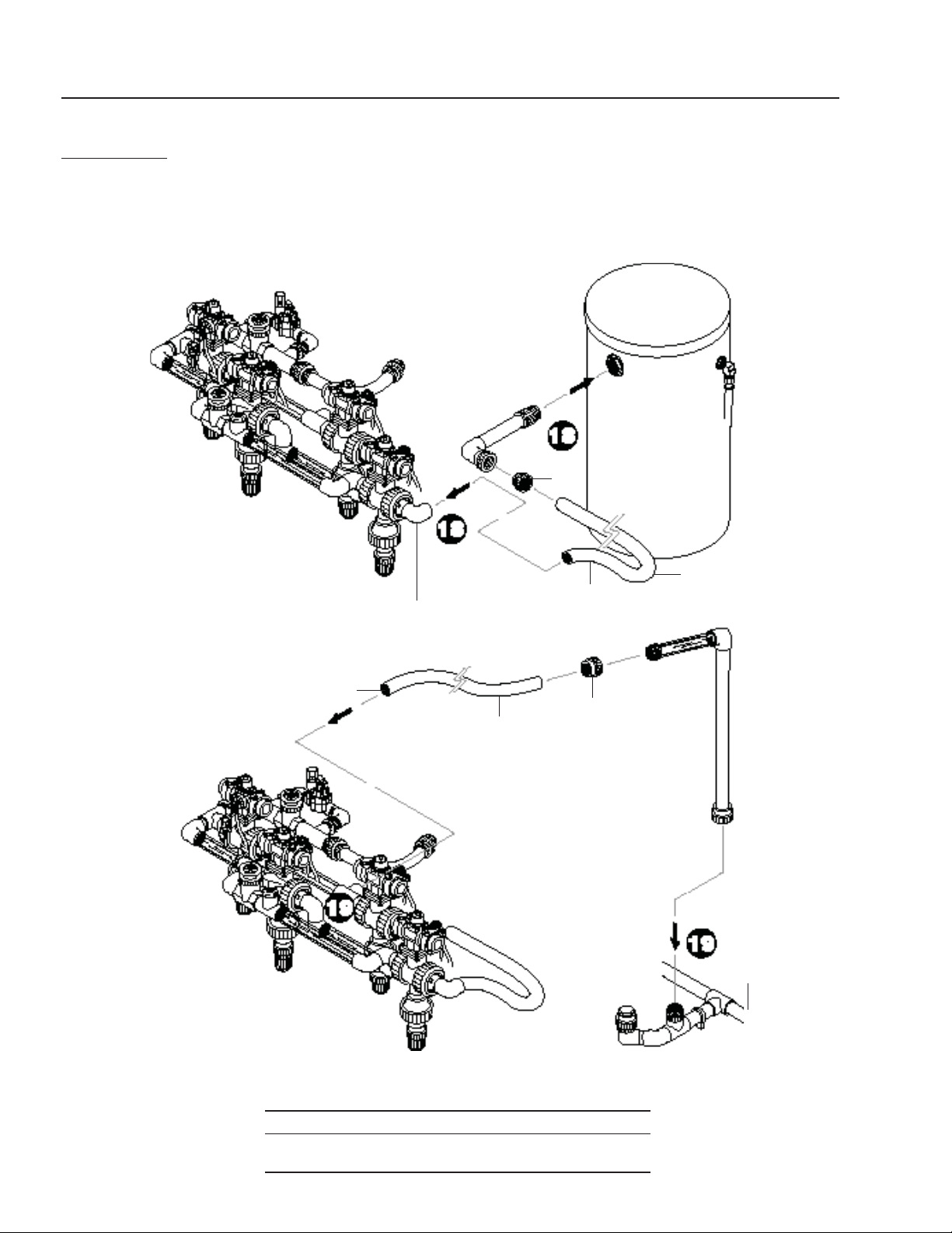
Step 16. Remove plumbing from return line off of the
carbon fi lter diverter valve to return line. Plug
both ends. Remove plumbing from carbon fi lter
diverter valve going to storage tank #2.
Step 17. Attach half union to remaining union (item 2)
on outlet from carbon fi lter. Glue elbow (item 4)
to union diverter valve as shown. Measure, cut
and glue 1-1/2" gray hose (item 3) to carbon
outlet port on AMC-3000.
AMC-3000
INSTALLATION INSTRUCTIONS (CONTINUED)
1-1/2"
Gray
Hose
Storage
Tank #2
Return
Line
Storage
Tank #2
Carbon Filter
Diverter Valve
Carbon
Filter
AMC-3000 Carbon Filter Outlet
Carbon
Filter
1
5
2
2
4
6
4
3
6
ITEM PART NO. DESCRIPTION
1 8.706-394.0 Plug, 1-1/2", PVC 80
2 8.706-470.0 Union, 1-1/2" Slip x Thread,
PVC 80 Spears
3 8.711-813.0 Hose, 1-1/2", Gray Spiralite, 50 ft.
ITEM PART NO. DESCRIPTION
4 8.706-374.0 Elbow, 1-1/2" S x S, PVC 80, 90°
5 8.706-424.0 Nipple, 1.5" x Close, PVC 80
6 8.706-367.0 Pipe, 1.5", PVC 80, 3 ft.
1
26
AMC / TDS OPERATOR’S MANUAL
Watermaze AMC/TDS Operator's Manual 8.913-965.0 - A
AMC-3000
INSTALLATION INSTRUCTIONS (CONTINUED)
Step 18. Build plumbing coming out of storage tank
#2 to AMC-3000 outlet elbow as shown.
Step 19. Connect plumbing coming out of AMC-3000
to union going to return line as shown
Return Line
Storage
Tank #2
1-1/2" Gray
Hose
AMC-3000
Outlet Elbow
1-1/2" Gray
Hose
2
1
2
1
ITEM PART NO. DESCRIPTION QTY.
1 8.711-813.0 Hose, 1-1/2", Gray Spiralite, 50 ft.
2 8.706-469.0 Union, 1-1/2" Slip x Slip, PVC 80
Spears
AMC / TDS OPERATOR’S MANUAL
27
Watermaze AMC/TDS Operator's Manual 8.913-965.0 - A
AMC-3000
INSTALLATION INSTRUCTIONS (CONTINUED)
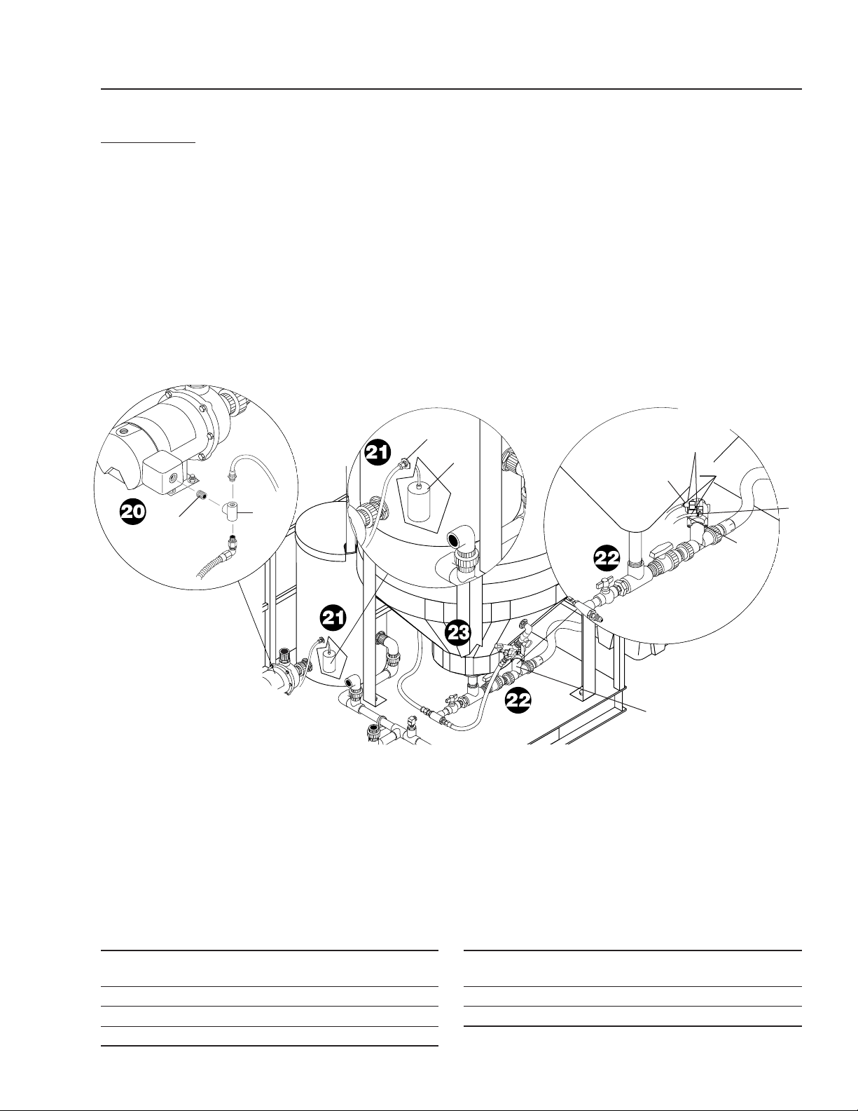
Step 20. Wire fi lter pump to AMC-3000 control box as
shown.
Step 21. Wire low limit fl oat (items 4 & 6) installed in
storage tank #1 into AMC-3000 control box
as shown.
Storage
Tank #1
Main
Tank
Cone
Dump
Valve
Assembly
1
ITEM PART NO. DESCRIPTION
1 9.802-254.0 Hose, 1/4", Push-On,
Fuel Line, 15 ft
2 8.706-467.0 Nipple, 1/2", PVC 80 Close
3 8.706-425.0 Tee, 1/2" Ft x Ft x Ft, PVC 80
4 9.802-515.0 Strain Relief, STRT, LQ Tite 3200
ITEM PART NO. DESCRIPTION
5 8.706-958.0 Hose Barb, 1/4" Barb x
1/4" Pipe, 90°
6 8.716-142.0 Switch, Float, N/O Black
7 8.716-697.0 Solenoid, Water Maze, PVC, 24V
Step 22. Wire dump valve assy to AMC-3000 control
box. Connect air lines to dump valve assembly.
Step 23. Wire water solenoid valve (item 7) to AMC-3000
control box as shown.
2
3
4
4
5
7
6
Air Lines
To Air
Regulator
Assy.
28
AMC / TDS OPERATOR’S MANUAL
Watermaze AMC/TDS Operator's Manual 8.913-965.0 - A
AMC-3000
Models Only
4
5
7
5
6
2
1
2
3
Sludge
Tub
Drain
Valve
4
8
9
9
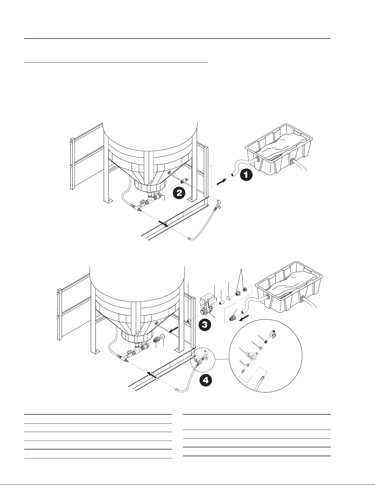
DUMP VALVE INSTALLATION INSTRUCTIONS
AMC-1000/AMC-3000
Step 1. Disconnect hose and move sludge tub away
from drain valve at the bottom of the cone
tank.
Step 2. Unscrew hose barb from drain valve.
Step 3. Attach dump valve assembly. Reconnect sludge
tub to dump valve assembly as shown.
Step 4. Install water solenoid valve as shown
(AMC-3000 only).
ITEM PART NO. DESCRIPTION
1 8.716-697.0 Solenoid, Water Maze, PVC 24V
2 8.706-926.0 Bushing, 1" x 1/2" Pipe
3 8.706-467.0 Nipple, 1/2", PVC 80 Close
4 8.706-367.0 Pipe, 2", Gray, PVC 80
5 8.706-451.0 Adapter, 2" Slip x MT, PVC 80
ITEM PART NO. DESCRIPTION
6 8.756-648.0 Valve, GEMU Silverline,
Threaded Ends & 2 Female
7 8.756-462.0 Solenoid, Air, GEMU Type 322
8 8.706-476.0 Union, 2" FS x FT, PVC 80
9 8.706-413.0 Bushing, 2' X 1 1/2' Slip, PVC 80
AMC / TDS OPERATOR’S MANUAL
29
Watermaze AMC/TDS Operator's Manual 8.913-965.0 - A
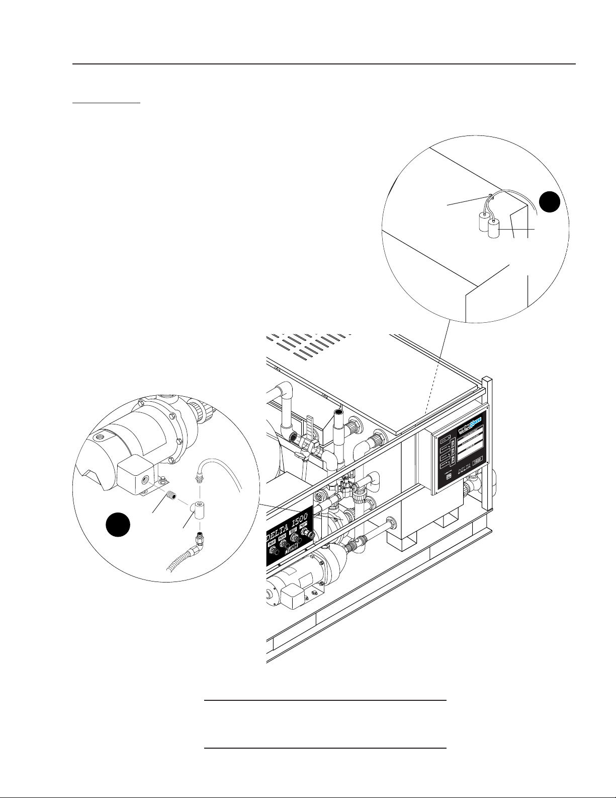
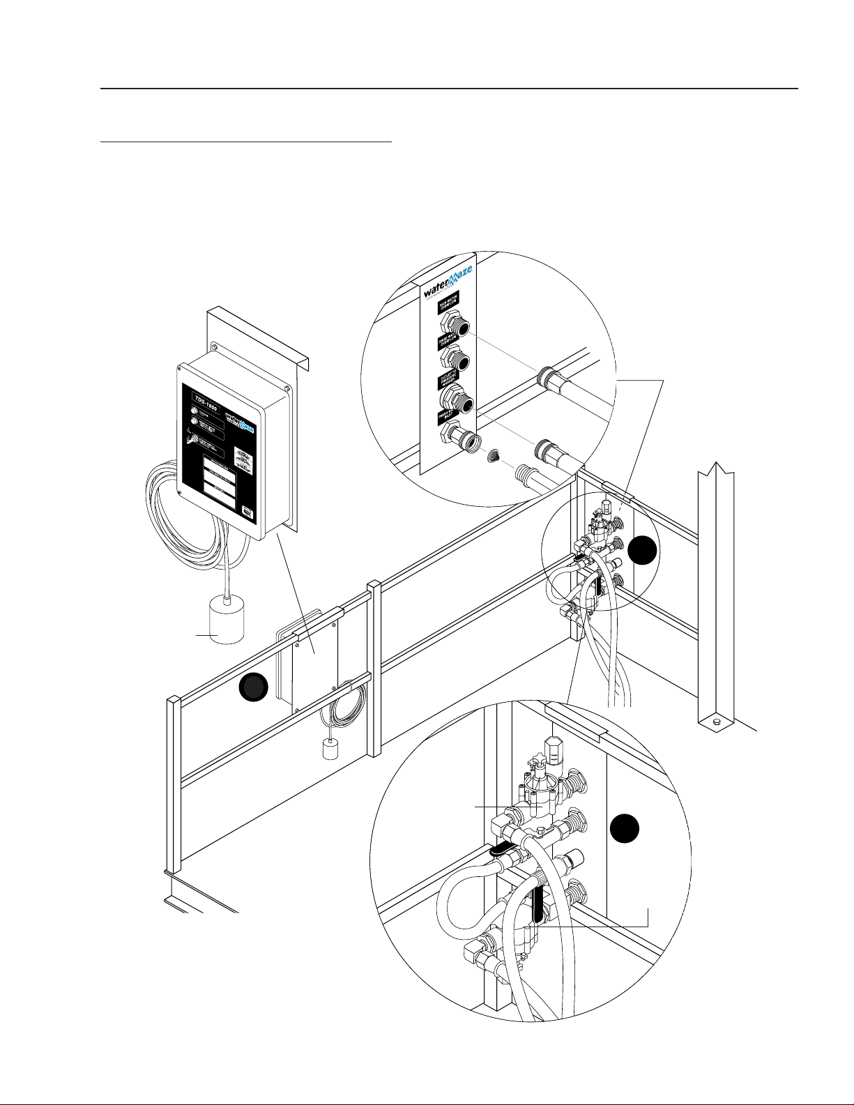
Step 1. Place TDS-1000 control box onto railing as
shown.
Water Panel
(Front View)
Step 2.
Wire rain water overfl ow valve and fresh water
inlet valve to TDS-1000 box per wiring diagram.
Float For
Optional
Storage Tank
TDS-1000
Control Box
Rain Water
Overfl ow
Fresh Water
Inlet
INSTALLATION INSTRUCTIONS
TDS-1000
2
1
2
30
AMC / TDS OPERATOR’S MANUAL
Watermaze AMC/TDS Operator's Manual 8.913-965.0 - A
CONTROL PANEL
AMC-2000/AMC-3000
AMC-3000
Models
Only
AMC-3000
Models Only
11
28
19
20
18
29
16
17
23
25
13
14
11
8
22
2
24
11
3
12
6
7
21
5
7
10
9
7
1
4
27
26
30
15
6
31

AMC / TDS OPERATOR’S MANUAL
31
Watermaze AMC/TDS Operator's Manual 8.913-965.0 - A
ITEM PART NO. DESCRIPTION QTY
1 8.716-281.0 Box, Plastic, 14" x 16" x 6.75"
w/Hinged Lid 1
2 8.913-206.0 Standoff, Electric Box 1
3 8.900-264.0 Label, AMC System 1
4 9.803-652.0 Light, Indicator, Green 28V 4
5 8.716-078.0 Switch, Toggle, 1-1/2" HP, 1 Pole,
P3CA201-73 1
6 9.802-759.0 Screw, 10/32" x 1/2" BHSOC
Blk 4
7 9.802-791.0 Nut, Cage, 10/32" x 16 GA 6
8 9.802-457.0 Din Rail, 35mm, /in. 6
9 9.802-467.0 Base, Relay, SH2B-05, IDEC 3
10 8.716-230.0 Relay, 24V, Finder 3
11 9.802-695.0 Nut, 10/32" KEPS 4
12 8.716-414.0 Block, Terminal, 23 Pole 1
13 8.751-306.0 Timer, Multi-Function,
24V-120/240V 1
14 8.716-439.0 Controller, Automatic
Maintenance (As of 1/02) 1
15 8.718-967.0 Washer 3
16 8.900-263.0 Label, Backwash Controller 1
17 8.724-267.0 Contactor, 15 Amp 1
18 8.716-883.0 Transformer, Micron, 208/230/
460V-24/115V, .050KVA 1
CONTROL PANEL PARTS LIST
AMC-2000/AMC-3000
ITEM PART NO. DESCRIPTION QTY
19 8.933-007.0 Fuse, KTK-R1 600V Midget 2
20 8.716-142.0 Switch, Float, N/O, .20 PMDWOP,
1003825 (Black) 1
21 9.802-525.0 Locknut, 1/2" 8463 8
22 9.802-515.0 Strain Relief, STRT,
LQ Tite 3200 10
23 8.716-460.0 Terminal, Grounding Lug,
LAMA6-14-Q 1
9.800-040.0 ▲ Label, Ground 1
24 9.802-762.0 Screw, 10/32" x 1-1/4" RH, SL,
Blk 1
25 9.802-494.0 Bar, Jumper 11
26 8.716-083.0 Plate, ON/OFF 1
27 8.716-081.0 Protector, Cover, Toggle Switch 1
28 8.900-421.0 Label, Control Panel
(AMC-3000) 1
8.940-168.0 Label, Control Panel
(AMC-2000) 1
29 9.803-977.0 Fuse, 2-1/2" Amp, 250V,
FNM2-1/2 1
30 8.718-936.0 Tek Screw 4
31 8.900-714.0 Tag, Warning, Filter Pump
Contactor Wiring 1
▲ Not Shown

32
AMC / TDS OPERATOR’S MANUAL
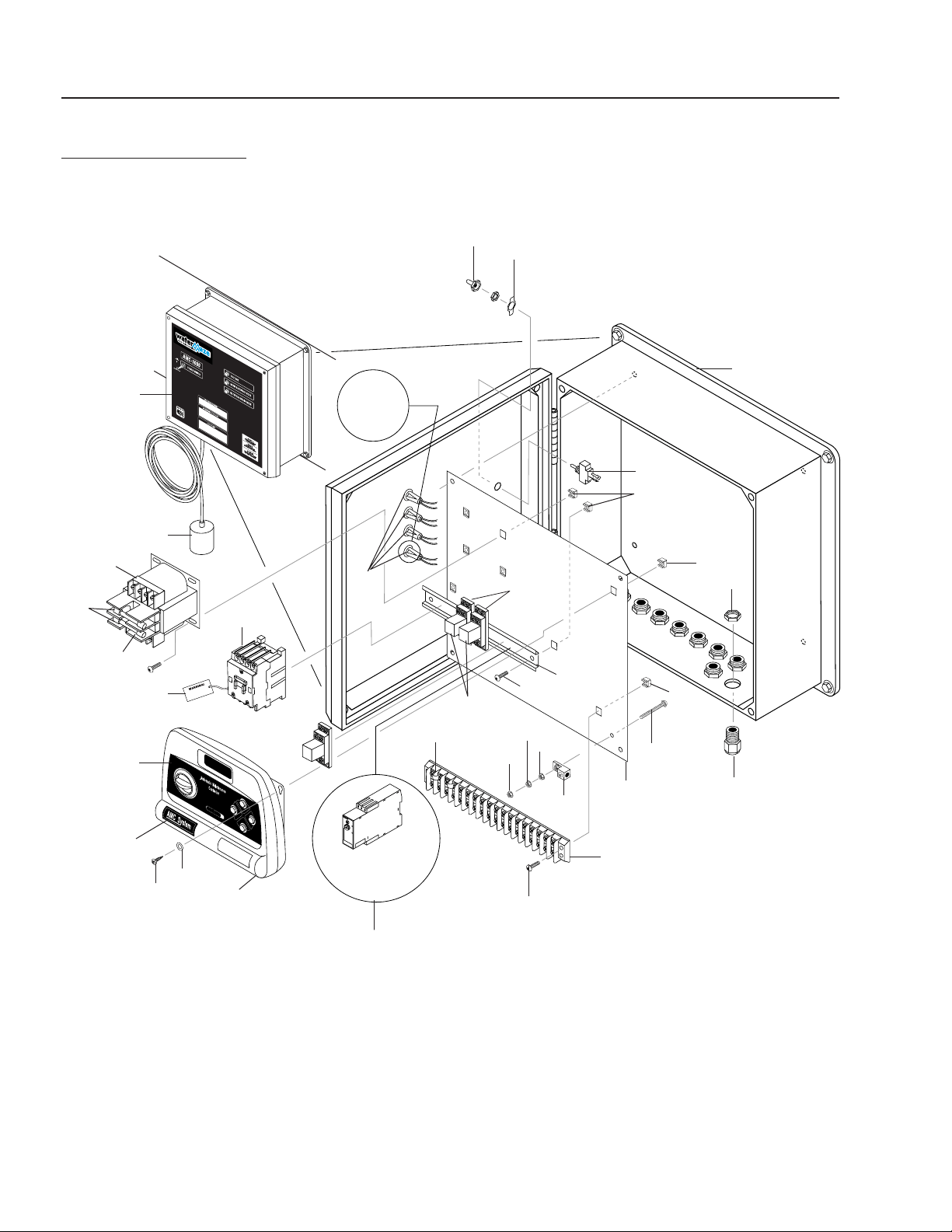
Watermaze AMC/TDS Operator's Manual 8.913-965.0 - A
CONTROL PANEL
AMC-1000/TDS-1000
35
29
30
32
28
28
27
25
26
31
33
34
7
5
3
21,22,23
1
4
2
8
14
12
11
TDS-1000
Only
9
16
10
8
13
17
6
TDS-1000
Units Only
15
18
19
20
38
37
AMC-1000
Units Only
AMC-1000
Units Only
36
24
8
39

AMC / TDS OPERATOR’S MANUAL
33
Watermaze AMC/TDS Operator's Manual 8.913-965.0 - A
CONTROL PANEL PARTS LIST
AMC-1000/TDS-1000
ITEM PART NO. DESCRIPTION QTY
1 8.716-272.0 Box, 12" x 10" x 5-1/4",
Separator 1
2 8.716-081.0 Protector, Cover, Toggle
Switch 1
3 8.716-078.0 Switch, Toggle, 1-1/2" HP,
1 Pole P#CA201-73 1
4 8.716-083.0 Plate, On/Off 1
5 9.802-455.0 Light, Indicator, Green 125V 1
6 9.802-515.0 Strain Relief, STRT, LQ Tite
3231 Small 3
7 9.802-525.0 Locknut, 1/2" 8463 3
8 8.718-936.0 Screw, #8 x 1/2", Tek Sq. Head,
SS 8
9 9.802-493.0 Block, Terminal, 16 Pole
(TDS-1000) 1
9.802-492.0 Block, Terminal, 8 Pole
(AMC-1000) 1
10 8.751-306.0 Timer, Multi-Function,
24V-120/240V 1
11 9.802-468.0 Relay, 120V, RH2B-UL-AC120 2
12 9.802-467.0 Base, Relay, SH2B-05, IDEC 2
13 9.802-457.0 Din Rail, 6 in. 1
14 8.716-253.0 Timer, 24 Hour Pin, 120V 20A 1
15 8.716-143.0 Switch, Float, N/C
1003826 (Gray) 1
16 9.802-749.0 Screw, 8/32" x 3/4" 2
17 8.920-278.0 Plate, Mount, Control Panel 1
8.716-460.0 ▲ Lug, Terminal Ground 1
9.800-040.0 ▲ Label, Ground 1
18 8.912-138.0 Bracket Electrical Box, 12 GA
MS, TDS System 1
19 8.900-420.0 Label, TDS Control Panel 1
8.940-169.0 Label, AMC-1000 Control Panel 1
20 8.933-007.0 Fuse, 1 Amp, Primary
(AMC-1000) 2
21 8.718-603.0 Bolt, 1/4" x 3/4", NC HH SS 4
22 8.718-817.0 Nut, 1/4" - 20, Hex Whiz Loc,
SS 4
ITEM PART NO. DESCRIPTION QTY
23 8.718-965.0 Washer, 1/4" SS, Flat 4
24 9.802-785.0 Nut, 8/32" Keps 2
25 8.707-177.0 Nipple, 1/4" MAL AIR
(AMC-1000) 1
26 8.707-331.0 Regulator, Air w/Filter,
1/4" Gauge (AMC-1000) 1
27 8.706-777.0 Nipple, 1/4" Close, P/N-3326-4
(AMC-1000) 1
28 8.706-915.0 Bushing, 1/2" x 1/4" Brass
(AMC-1000) 2
29 9.802-961.0 Hose Connection Bracket
(AMC-1000) 1
30 8.706-958.0 Hose Barb, 1/4" Barb x 1/4" Pipe,
90° (AMC-1000) 1
31 6.390-126.0 Clamp, Hose, UNI .46 - .54 1
32 8.900-210.0 Label, Warning, 100 PSI Air Pres.
(AMC-1000) 1
33 8.718-621.0 Bolt, 5/16" x 1", HH, NC, SS
(AMC-1000) 2
34 8.718-980.0 Washer, 5/16", Flat, SAE
(AMC-1000) 2
35 8.718-887.0 Nut, 5/16", SS, Whiz Loc
(AMC-1000) 2
36 9.802-494.0 Bar, Jumper 1
37 9.802-553.0 Transformer, 120/240-24V,
.050 KVA (AMC-1000) 1
38 9.803-977.0 Fuse, 2.5 Amp, Secondary
(AMC-1000) 1
39 9.802-455.0 Light Indicator, Green, 125V
(TDS-1000) 1
9.803-652.0 Light, Indicator, Green 28V 1
34
AMC / TDS OPERATOR’S MANUAL
Watermaze AMC/TDS Operator's Manual 8.913-965.0 - A
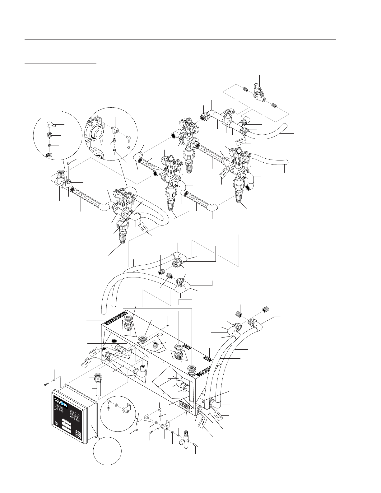
EXPLODED VIEW
AMC-2000/AMC-3000
To Filter
Pump
For Detail
See Control
Panel Illus.
To Carbasorb
Filter Inlet
To Multi-Media
Filter Inlet
To Storage
Tank #2
To Main
Drain Line
To Multi-Media
Filter Outlet
AMC-2000
Models Only
2
1
2
3
4
7
8
37
3
4
8
6
5
5
9
377
7
9
10
9
10
44
11
7
11
7
38
11
7
7
10
37
7
20
20,41
20
7
7
8
7
37
21
21
21
21
26
25
22
7
7
37
22
7
7
29
31
30
32
33
34
24
23
33
15
35
36
35
15
28
23
24
20
39
40
7
37
37
11
7
9
7
42
6
7
53
16
17
7
7
10
19
18
12
13
14
15
7
48
21
27
7
50
43
15
14
20
46
47
45
45
46
45
47
45
AMC-3000
Models Only
51
52
To Carbasorb
Filter Outlet
54
57
56
55
58

AMC / TDS OPERATOR’S MANUAL
35
Watermaze AMC/TDS Operator's Manual 8.913-965.0 - A
EXPLODED VIEW PARTS LIST
AMC-2000/AMC-3000
ITEM PART NO. DESCRIPTION QTY
1 8.716-697.0 Solenoid, Water Maze, PVC 24V1
2 8.706-439.0 Nipple, 1", PVC 80, Close 2
3 8.706-378.0 Elbow, 1" SLIP X FIPT,
PVC 80, 90° 2
4 8.706-597.0 Union, "1, S x S,
PVC 80 Spears 2
5 8.706-431.0 Tee, 1-1/2" x 1-1/2" x 1" SLIP,
PVC 80 2
6 8.707-344.0 Valve, PVC 1.5" SLIP x SLIP,
Gate 2
7 8.706-374.0 Elbow, 1-1/2" SxS, PVC 80, 90° 24
8 8.706-469.0 Union, 1-1/2" SLIP x SLIP,
PVC 80 Spears 3
9 8.749-845.0 Valve, 3-Way Diverter W/Air
Actuator 4
10 8.706-426.0 Tee, 1.5" S x S x S, PVC 80 4
11 8.706-441.0 Adapter, 1.5" x 1.5" FT x SLIP,
PVC 80 4
12 8.706-857.0 Tee, 1/8" Street 3
13 8.706-940.0 Hose Barb,
1/4" Barb x 1/8"ML Pipe 3
14 8.706-955.0 Hose Barb, 1/4" Barb x 1/8" ML
Pipe, 90° 4
15 6.390-126.0 Clamp, Hose, UNI .46 - .54 7
16 8.716-157.0 Protector, Pressure Switch,
3302-001 1
17 8.716-158.0 Switch, Pressure, 15 PSI 1
18 8.706-914.0 Bushing, 1/2" x 1/8" Pipe 1
19 8.706-406.0 Bushing, 1-1/2" x 1/2" SPG x FT,
PVC 80 1
20 8.706-470.0 Union, 1-1/2" SLIP x Thread
PVC 80 Spears 4
21 8.706-424.0 Nipple, 1.5" x Close, PVC 80 8
22 8.718-887.0 Nut, 5/16", SS Whiz Loc 6
23 8.718-621.0 Bolt, 5/16" x 1", HH, NC, SS 6
24 8.718-980.0 Washer, 5/16", Flat, SAE 6
25 8.900-461.0 Label, Return 1
26 8.900-530.0 Label, Tank 2, Clar., Lexan 1
27 8.900-454.0 Label, Carbasorb Filter 1
28 8.900-210.0 Label, Warning, 100 PSI
Air Pressure 1
ITEM PART NO. DESCRIPTION QTY
29 8.706-421.0 Hanger, Pipe, 1-1/2" Click #47 4
30 8.707-177.0 Nipple, 1/4" Mal Air 1
31 8.707-331.0 Regulator, Air w/Filter,
1/4" Gauge 1
32 8.706-777.0 Nipple, 1/4" Close 1
33 8.706-915.0 Bushing, 1/2" x 1/4" Brass 2
34 9.802-961.0 Hose Connection Bracket 1
35 8.706-958.0 Hose Barb,
1/4" Barb x 1/4" Pipe, 90° 2
36 8.706-854.0 Tee, 1/4" Branch 1
37 8.711-815.0 Hose, 1-1/2" Gray Conduit /ft. 50
38 8.706-360.0 Pipe, 1.5" PVC Clear 10"
39 8.912-139.0 Panel, Manifold, AMC 1
40 8.900-451.0 Label, Multi-Media Filter 1
41 8.706-424.0 Nipple, 1.5" Close PVC,
SCH. 80 4
42 8.706-360.0 Pipe, 1.5" PVC Clear 13.25"
43 8.706-360.0 Pipe, 1.5" PVC Clear 9.75"
44 8.706-360.0 Pipe, 1.5" PVC Clear 15"
45 8.706-367.0 Pipe, 1.5" PVC SCH. 80 (9.75") 4
46 8.706-367.0 Pipe, 1.5" PVC SCH. 80 (18") 2
47 8.706-367.0 Pipe, 1.5" PVC SCH. 80 (6") 2
48 8.706-360.0 Pipe, 1.5" PVC Clear
SCH. 80 3.25"
49 9.802-254.0 ▲ Hose, 1/4", Air Line 12 ft.
50 8.706-387.0 Plug, 1/2" 1
51 8.900-710.0 Tag, Carbasorb Outlet Port,
AMC 1
52 8.900-709.0 Tag, Carbasorb Inlet Port, AMC 1
53 8.900-707.0 Tag, Multi-Media Inlet Port,
AMC 1
54 8.900-708.0 Tag, Multi-Media Outlet Port,
AMC 1
55 8.900-711.0 Tag, Filter Pump Inlet, AMC 1
56 8.900-713.0 Tag, Backwash Return, AMC 1
57 8.900-712.0 Tag, Tank #2 Inlet, AMC 1
58 8.706-787.0 Bulkhead, 1-1/2" 4
▲ Not Shown

AMC / TDS OPERATOR’S MANUAL
37
Watermaze AMC/TDS Operator's Manual 8.913-965.0 - A
WATER MAZE LIMITED NEW PRODUCT WARRANTY
WASH-WATER SYSTEMS
WHAT THIS WARRANTY COVERS
All WATER MAZE wash-water systems are warranted by WATER MAZE to the original purchaser to be free from defects in
materials and workmanship under normal use, for the periods specifi ed below. This Limited Warranty, subject to the exclusions
shown below, is calculated from the date of the original purchase, and applies to the original components only. Any parts replaced
under this warranty will assume the remainder of the part’s warranty period. A 60 day grace period will be given for installation.
ONE YEAR PARTS AND 30 DAY LABOR WARRANTY:
All components excluding normal wear items as described below.
WARRANTY PROVIDED BY OTHER MANUFACTURERS:
Motors, which are warranted by their respective manufacturers, are serviced through these manufacturers’ local authorized
service centers. WATER MAZE cannot provide warranty on these items.
NON-WARRANTY REPLACEMENT PARTS:
These parts, excluding normal wear items as described below, will be warranted for the duration specifi ed by the original com-
ponent manufacturer. O-rings and leaks at glued fi ttings are covered the fi rst time on original start-up only.
WHAT THIS WARRANTY DOES NOT COVER
This warranty does not cover the following items:
1. Normal wear items, such as mechanical seals, fi lters, gaskets, O-rings, check valves, fi ltering media, ozone bulbs.
O-rings and leaks at glued fi ttings are covered the fi rst time on original start-up only.
2. Damage or malfunctions resulting from accidents, abuse, modifi cations, alterations, incorrect installation, improper
servicing, failure to follow manufacturer’s maintenance instructions, or use of the equipment beyond its stated usage
specifi cations as contained in the operator’s manual.
3. Damage due to freezing, chemical deterioration (oxidation, chloride or fl uoride corrosion).
4. Damage to components from fl uctuations in electrical or water supply.
5. Normal maintenance service, including adjustments.
6. Transportation to service center, fi eld labor charges, or freight damage.
7. Death of microbes (Biostax 900 & 100) from lack of refrigeration after received and stored.
WHAT YOU MUST DO TO OBTAIN WARRANTY SERVICE
While not required for warranty service, we request that you register your WATER MAZE Product by returning the completed
registration card. In order to obtain warranty service on items warranted by WATER MAZE, you must return the product to your
Authorized WATER MAZE Dealer, freight prepaid, with proof of purchase, within the applicable warranty period. If the product is
permanently installed, you must notify your Authorized WATER MAZE Dealer of the defect. Your Authorized WATER MAZE Dealer
will fi le a claim with WATER MAZE, who must subsequently verify the defect. In most cases, the part must be returned to WATER
MAZE freight prepaid with the claim. For warranty service on components warranted by other manufacturer’s, your Authorized
WATER MAZE Dealer can help you obtain warranty service through these manufacturers’ local authorized service centers.
LIMITATION OF LIABILITY
WATER MAZE’S liability for special, incidental, or consequential damages is expressly disclaimed. In no event shall
WATER MAZE’S liability exceed the purchase price of the product in question. WATER MAZE makes every effort to ensure that
all illustrations and specifi cations are correct, however, these do not imply a warranty that the product is merchantable or fi t for a
particular purpose, or that the product will actually conform to the illustrations and specifi cations. THE WARRANTY CONTAINED
HEREIN IS IN LIEU OF ALL OTHER WARRANTIES, EXPRESS OR IMPLIED, INCLUDING ANY IMPLIED WARRANTY OF
FITNESS FOR THE PARTICULAR PURPOSE, INCLUDING QUALITY OF WATER TREATMENT. WATER MAZE does not au-
thorize any other party, including authorized WATER MAZE Dealers, to make any representation or promise on behalf of WATER
MAZE, or to modify the terms, conditions, or limitations in any way. It is the buyer’s responsibility to ensure that the installation
and use of WATER MAZE products conforms to local codes. While WATER MAZE attempts to assure that its products meet
national codes, it cannot be responsible for how the customer chooses to use or install the product.
WATER MAZE
www.wmaze.com • 1-360-833-2333 • 1-800-535-0941

Watermaze AMC/TDS Operator's Manual 8.913-965.0 - A • Printed in U.S.A.