1

1. Place Jack on floor and press down on pedal to release pedal lock. Pull out the lock pin from frame.
2. Before operating, open release valve by turning hand-wheel counterclockwise. Expand Jack by hand-wheel
enough to place around tire and position so both rollers now contact the tire tread. To obtain the best
control of Jack while expanding around tire, place your left hand and on top of the left side axle and your
right hand at the center of the pedal. Close release valve by turning hand-wheel clockwise to a snug-tight
position, Jack may now be used.
3. Install Jack so that the unit is parallel to the sidewall of the tire to be lifted. Leave approximately 3/4" of
clearance between tire and Jack. This is especially important. If unit is misaligned, it is possible that the tire
will be forced to hit the axle of the Jack and not the rollers, this may damage the Jack and void the warranty.
4. To lift tire, flip directional lever up and place foot on pedal depressing with smooth, even strokes. Cycle pedal
until tire is lifted from surface once inch or less. After lifting, the lower the tire is to the ground the more
stable Jack will be. After lifting, be sure always lock the pin in place before operating. Repeat process on
the other tires and maneuver the vehicle as required.
5. To release Jack, pull the pin out from frame and open valve by turning hand-wheel counterclockwise slowly.
Jack may be removed when rollers disengage from tire.
WARNING!
Read all the instructions and warnings first before attempting to operate this Jack.
1. DO NOT operate Jack on inclined surfaces. Jack must be used on level surfaces only. Unanticipated motion
will occur as soon as Jack lifts tire from surface.
2. DO NOT overload Jack’s beyond the load rating (1500lbs per unit).
3. DO NOT start the vehicle’s engine, or drive with Jack in use. Jacks are designed for hand maneuvering of
vehicles only.
4. DO NOT use Jack to lift tires wider than 12 inches.
5. DO NOT attempt to push Jack over obstacles. They are designed to be used on level and reasonable smooth
surfaces only.
6. After lifting, be sure always lock the pin in place before operating. Pull the pin out after finishing work and
then release the value.
OPERATING INSTRUCTIONS
1
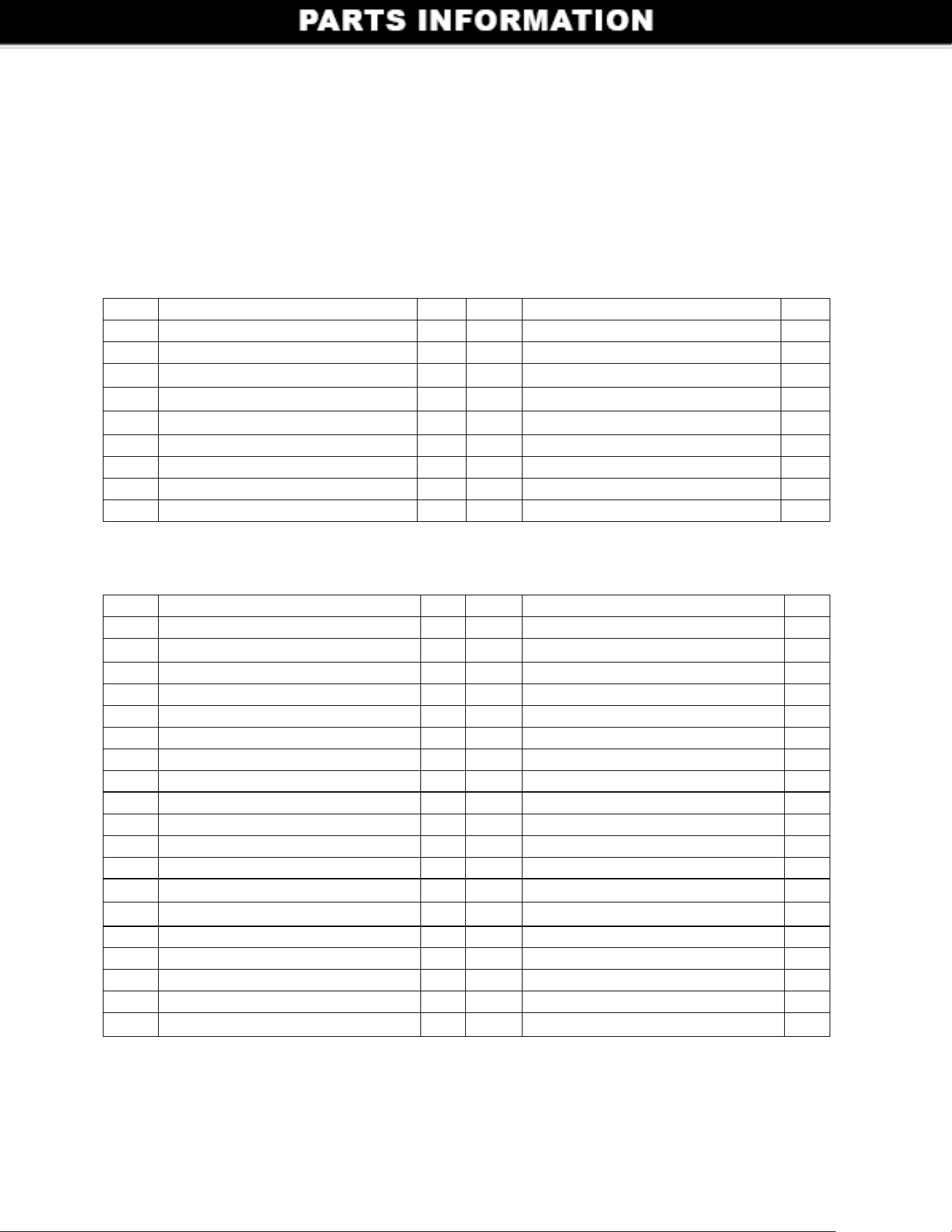
Ref # Description QTY Ref # Description QTY
19 Foot Pedal 1 38 Rectangle Seal Ring 1
20
Pedal Pin Ø8x28
3 39 Release Valve 1
21 Connecting Rod 1 40 Tank Washer 2
22 Connecting Bolt 1 41 Ram 1
23 Spring Cover 1 42 Cylinder 1
24 Flat Washer 1 43 Oil-plug 1
25 Spring 1 44 Tank 1
26 Pump 1 45 Y-Ring 1
27 Pump Core 1 46 Piston 1
28 O-Ring 1 47 Piston O-Ring 1
29 Back-up Ring 1 48 Bowl Seal Ring 1
30 Screw M10x1.25 1 49 Tank Nut 1
31 Small Spring 1 50
Steel Ball Ø6
1
32
Steel Ball Ø6
3 51 Steel Ball Seat 1
33 Cylinder Copper Washer 1 52 Safety Valve Spring 1
34 Ram Base 1 53 Safety Valve Screw 1
35 Copper Washer 1 54 O-Ring 1
36 Screw M5 2 55 Screw 1
37
Steel Ball Ø5
1
PARTS LIST OF VEHICLE POSITIONING JACK
Ref # Description QTY Ref # Description QTY
1 Ram Assembly 1 10 Left Frame 1
2 Bolt M16x115 1 11 Lock Pin with Chain 1
3 1 12 Screw M6x20 4
4
Flat Washer Ø 16
Nut M16 1 13 4
5 Roller Raceway 4 14 4
6 Roller 2 15
Lock Washer Ø6
Flat Washer Ø6
Right Frame 1
7 Raceway Lock Screw 8 16 Hook 1
8 Lock Nut M12 4 17 Washer for Hook 1
9 4” Swivel Caster 4 18 Nut for Hook 1
2