
55CC POST HOLE DIGGER+1O" ICE BIT AUGER
ITEM: 81093
OWNER'S MANUAL AND SAFETY INSTRUCTIONS
SAVE THIS MANUAL: KEEP THIS MANUAL FOR SAFETY WARNINGS, PRECAUTIONS, ASSEMBLY,
OPERATING, INSPECTION, MAINTENANCE AND CLEANING PROCEDURES. WRITE THE PRODUCT'S
SERIAL NUMBER ON THE BACK OF THE MANUAL NEAR THE ASSEMBLY DIAGRAM (OR MONTH
AND YEAR OF PURCHASE IF PRODUCT HAS NO NUMBER)
FOR QUESTIONS PLEASE CALL OUR CUSTOMER SUPPORT: (909) 628 0880 MON-FRI 9AM TO 3PM PST

IMPORTANT SAFETY INFORMATION
GENERAL SAFETY WARNINGS
Read all safety warnings and instructions. Failure to follow the warnings and instructions may
result in electric shock, fire and/or serious injury. Save all warnings and instructions for future
reference.
The warnings, precautions, and instructions discussed in this instruction manual cannot cover all possible
conditions and situations that may occur. It must be understood by the operator that common sense and
caution are factors which cannot be built into this product, but must be supplied by the operator. Read
carefully and understand all ASSEMBLY AND OPERATION INSTRUCTIONS before operating. Failure
to follow the safety rules and other basic safety precautions may result in serious personal injury.
• Read and understand all instructions. Failure to follow all instructions may result in serious injury or
property damage.
•
DO NOT allow persons to operate or assemble the product until they have read this manual and have
developed a thorough understanding of how it works.
• DO NOT modify this product in any way. Unauthorized modification may impair the function and/or
safety and could affect the life of the product. There are specific applications for which the product was
designed.
• Use the right tool for the job. DO NOT attempt to force small equipment to do the work of larger
industrial equipment. There are certain applications for which this equipment was designed. This product
will be safer and do a better job at the capacity for which it was intended. DO NOT use this equipment for
a purpose for which it was not intended.
•
Keep children and bystanders away from the work area while operating the tool. DO NOT allow
children to handle the product.
• Buried utility lines may be unmarked; contact utility companies before drilling. Contacting utility lines
may cause severe personal injury or death.
• Check for landscape fabric before drilling. Landscape fabric may get pulled into the Bit and also pull
the operator into the Bit. Before drilling, cut a hole in the landscape fabric sufficiently larger than the
diameter of the Auger to prevent contact or entanglement with the fabric.
•
Keep everyone other than the operator at least 10 feet from the Auger during operation. People
using hand tools should not move or remove soil-pile while the Auger is operating. Always keep children
away from the Auger, especially while it is operating.
•
To prevent severe personal injury or dismemberment from rotating Bit: Stand on flat, level, solid surface
and brace against torque during use. Keep hands and feet away from Bit and hole when Engine is
running.
• DO NOT lock trigger on. Never disable safety switches or components.
• Maintain a firm grip on the Auger with both hands and be aware of the strong start-up torque of the tool.
• Disconnect and insulate spark plug wire before maintenance and/or changing bits.
• DO NOT carry between holes with Engine running.
• Carry by handle only; not by Bit. Keep your thumb near the power Switch in the event the Auger must
be turned off immediately.
1

• DO NOT use the Auger
if
the Bit
is
dull, bent,
or
damaged.
• Drill with the Engine running at full speed. Fully squeeze the Throttle to maintain a steady
drilling
speed.
•
\/\/hen shutting off the Engine, make sure the Auger has stopped before setting the tool
down.
• Fire Hazard! DO NOT fill fuel tank while engine is running. DO NOT operate if gasoline has been spilled.
Clean spilled gasoline before starting engine. DO NOT operate near pilot light or open flame.
• DO NOT touch engine during use. Let engine cool down after use.
• Never store fuel
or
other flammable materials
near
the engine.
• Only use a suitable means of transport and lifting devices with sufficient weight bearing capacity when
transporting the Auger. Secure the Auger on transport vehicles to prevent it from rolling, slipping, and
tilting.
• Industrial applications must follow OSHA requirements.
• DO NOT leave the Auger unattended when it
is running. Turn
off the Auger (and remove safety keys,
if
available) before leaving the
work
area.
• The Auger
can
produce high noise levels. Prolonged exposure to noise levels above 85 dBA
is
hazardous
to hearing. Wear ear protection when operating the Auger
or
when
working
nearby while it
is
operating.
• Wear ANSI-approved safety glasses, hearing protection, and NIOSH-approved dust mask/
respirator
under
a
full-face shield along with
steel-toed
work boots during use.
• People with pacemakers should consult their physician(s) before use. Electromagnetic fields
in
close
proximity to a heart pacemaker could cause pacemaker interference
or
pacemaker failure. Caution
is
necessary when near
the
engine's magneto or recoil starter.
• Use this Auger with both hands only. Using Auger with only one hand
can
easily result
in
loss of control.
• Dress properly. DO NOT wear loose clothing or jewelry. Keep hair, clothing and gloves away from moving
parts. Loose clothes, jewelry or long hair can be caught in moving parts.
• DO NOT smoke, or allow sparks, flames, or other sources of ignition around the Auger, especially when
refueling.
• \/\/hen spills of fuel or oil occur, they must be cleaned up immediately. Dispose of fluids and cleaning
materials as per any local, state, or federal codes and regulations. Store oil rags in a bottom-ventilated,
covered, metal container.
• Before use, check for misalignment or binding of moving parts, breakage of parts, and any other condition
that may affect the Auger's operation. If damaged, have the Auger serviced before
using.
• Anyone
using vibrating
tools regularly
or for
an extended period should
first
be examined by a doctor
and then have regular medical check-ups
to
ensure medical problems are not being caused or worsened
from use. Pregnant women
or
people who have impaired blood
circulation
to the hand, past hand injuries,
nervous
system disorders, diabetes,
or
Raynaud's Disease should not use this tool. If you feel any
symptoms related to
vibration
(such as tingling, numbness, and white
or
blue fingers), seek medical
advice as
soon
as possible.
• To reduce vibration, maintain the tool as explained in this manual. If any abnormal vibration occurs, stop
use immediately.
• Before service, maintenance, or cleaning: Turn the engine switch to its "OFF" position. Allow the engine
to completely cool. Then, remove the spark plug cap from the spark plug.
2

IMPORTANT! A. You do not operate the Auger Drill with the proper 25:1 fuel
mix in
the fuel tank. DO NOT
run the engine with an improper fuel
mix,
low or no fuel
mix. Running
the engine with an improper fuel
mix,
low or no fuel
mix,
can permanently damage the unit. B. You
fail
to operate the Auger Drill with the proper
amount of SAE 80-90 gear
oil in
its Gearbox. DO NOT run the Auger Drill with low, or no gear
oil. Running
the Auger Drill with low or no gear
oil
can permanently damage the unit. C. Maintain labels and nameplates
on the Auger Drill. These carry important information. D. Always wear safety equipment. When operating
the Auger Drill, wear ANSI approved safety impact eye goggles, hearing protection, heavy duty work gloves,
sturdy steel-toe boots and
head
protection.
CARBON MONOXIDE PRECAUTIONS
This Auger Drill is designed for outdoor use only. DO NOT operate this drill in indoor, closed or poorly
ventilated areas. When running, the engine of this product produces carbon monoxide, a colorless and
odorless toxic gas that, when inhaled, can cause serious personal injury or death.
FIRE AND EXPLOSION PRECAUTIONS
Gasoline fuel and fumes are flammable and potentially explosive. Use proper fuel storage and handling
procedures. Have multiple ABC class fire extinguishers nearby when using this power tool. Keep the Auger
Drill and surrounding areas clean and dust free at all times.
1. If
oil
or fuel spills occur, they must be cleaned up immediately. Dispose of fluids and cleaning materials as
per any local state or federal codes and regulations. Store
oil
rags
in
a covered metal container.
2. DO NOT store fuel or other flammables near the Auger Drill.
3. DO NOT smoke or allow sparks, flames or other sources of ignition around the Auger Drill.
4. Keep grounded conductive objects such as tools away from exposed, live electrical parts and connections
to avoid sparking or arcing. Failure to do so could ignite fumes or vapors.
5. DO NOT refill the fuel tank while the engine is running or while the engine is still hot. DO NOT operate the
Auger Drill with any known leaks on the fuel system.
6. Use only manufacturer recommended fuel and oil.
7. Prior to performing service, maintenance or cleaning procedures, allow the engine to completely cool.
Then, remove the spark plug from the engine.
8.DO NOT alter or adjust any part of the Auger Drill or engine that is assembled and supplied by the
manufacturer.
9. Follow scheduled Auger drill engine maintenance.
CHEMICAL PRECAUTIONS
1. Avoid contact with hot fuel, oil and exhaust fumes.
2. Avoid body contact with fuels, oils and lubricants used in the Auger Drill and engine. If swallowed,
seek medical attention immediately. DO NOT induce vomiting if fuel is swallowed. For skin contact,
immediately wash with soap and water. If fuel gets in the eyes, immediately flush eyes with clean
water.
WARNING: This product contains or, when used, produces a chemical known to the state of California
to cause cancer and
birth
defects
or
other
reproductive
harm.
(California
Health and Safety Codes
25249.5, et seq.)
NOTE: This
item
does not meet
California
CARB
requirements
and
is
not
for
sale
or
use
in California.
3
ASSEMBLY AND OPERATION
ASSEMBLY
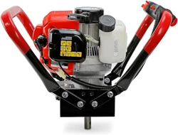
Insert the shank of the Auger (33a) fully upward into the Transmission Shaft (15a). Align the mounting holes
in the Auger and Transmission Shaft. Then secure the Auger to the Auger Drill using the Pin (34a) and Safety
Pin (35a).
SAFE1Y P 13:ia)
PRE-START INSTRUCTIONS
Pl
(34.a)
TRANS ISS SHAFT
I
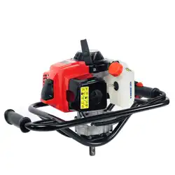
1. Fill the fuel tank: To obtain the proper 25: 1 fuel mix, combine 25 parts
unleaded gasoline (89+ octane) with 1 part 2-cycle oil in the provide
Fuel Mix Container (36a). Cover and shake to thoroughly mix before
each fueling.
NOTE: Mix only enough fuel for a few days work. The maximum
storage time of mixed fuel is three months.
1 GALLON
UNLEADED
GASOLINE
2. Once the proper fuel mix is obtained, removed the Fuel Cap (93). Fill the Fuel Tank (89) approximately¾
full with the fuel mix. Then replace the Fuel Cap. See Figure B.
WARNING: Do not attempt to fill the Fuel Tank (89) when the engine is running or hot to the touch.
4
OPERATION
FIGURE C
STARTING AND STOPPING THE AUGER DRILL
F
E
··•
.
. .
. - .
. _,,-:;a,,L__
.
/
STARTER-.....-iil::.
(7)
..-
1. Place the Auger Drill on its side with the Auger (33a) resting upon the ground surface location that is to
be drilled. Make sure no debris, clothing or other objects ore near the Auger Bit. Keep all bystanders a safe
distance away.
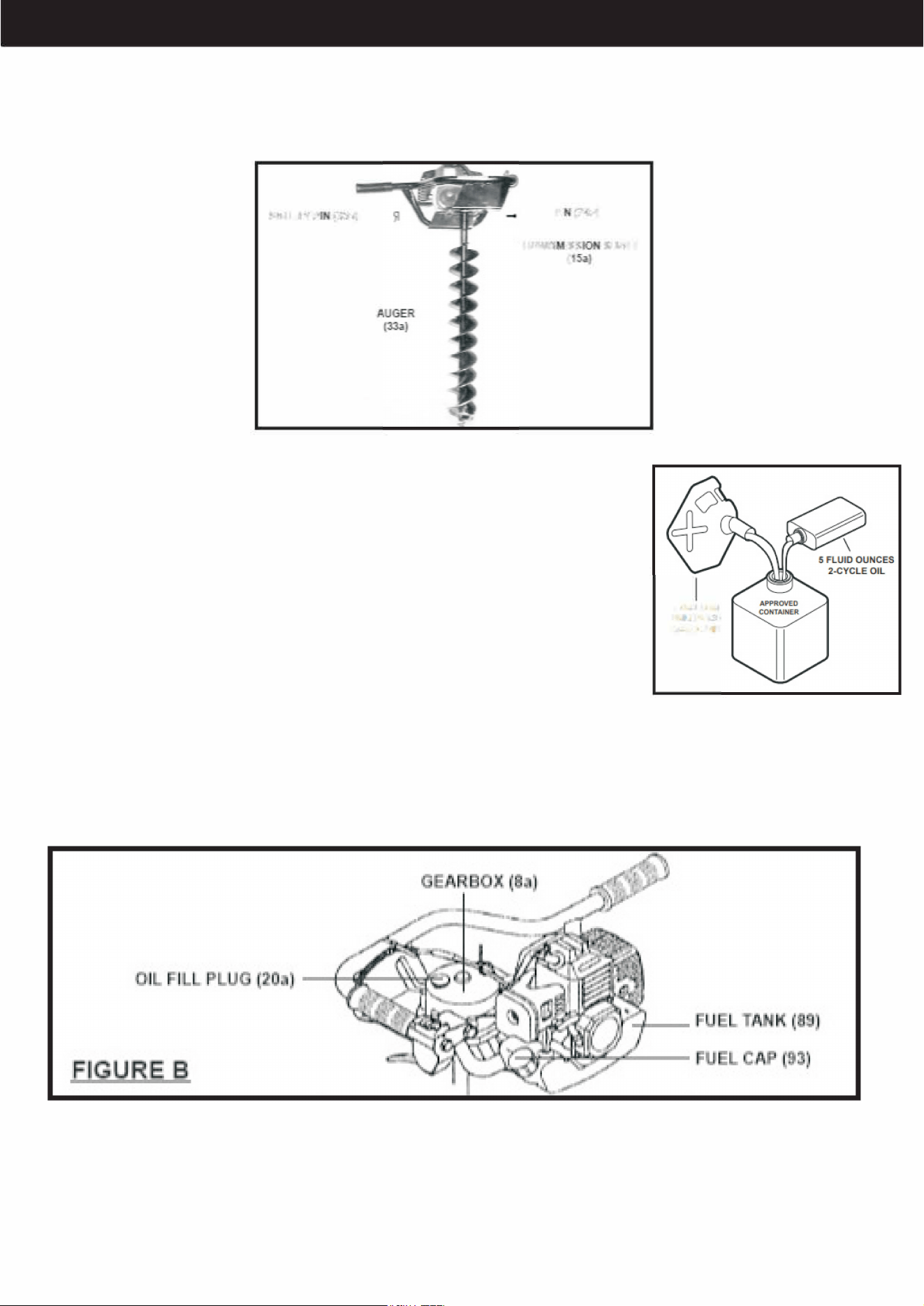
2. Depress the Primer (95) three to four times. See figure C.
3. Set the Choke (76) to the appropriate position: Closed if the engine is cold. Open of the engine is warm.
See Figure C.
4. Grip the Frame (1 b) firmly with your left hand. Keep all body parts away from the bit. Then, with your right
hand. Pull rapidly on the Starter Handle (7) to start the engine. See Figure C.
5. Once the engine is started, set the Choke (76) to its open position.
6. If the engine does not start, press the Primer (95) again. Set the Choke (76) to its closed position and
again attempt to start the engine. See Figure C.
7. Once the engine is started, set the choke to its open position.
8. If the engine does not start press the Primer (95) again. Set the choke to its closed position and again
attempt to start the engine. See Figure C.
NOTE: If the engine is new or has been stored for a long period of time, pull the Starter Handle (7) several
times to ensure sufficient fuel is delivered into the fuel line and combustion chamber of the engine. See
Figure C.
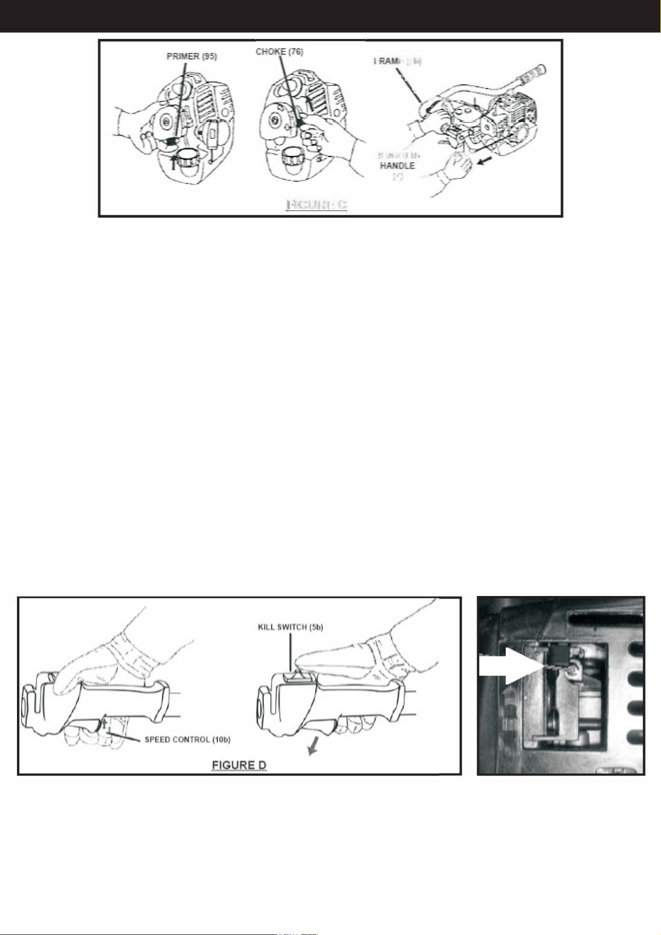
9. As soon as the engine is running, check to make sure the Choke (76) is in its open position. Squeeze
the Speed Control (1 Ob) briefly and let up. The Speed Control will revert to its original position, causing the
engine to idle. See Figure C and D
10. To stop the Auger Drill, release pressure on the Speed Control (10b). Then press down on the Kill Switch
(Sb). Keep your thumb near the Kill Switch in the event the Auger Drill must be stopped immediately. See
Figure D.
5
OPERATION
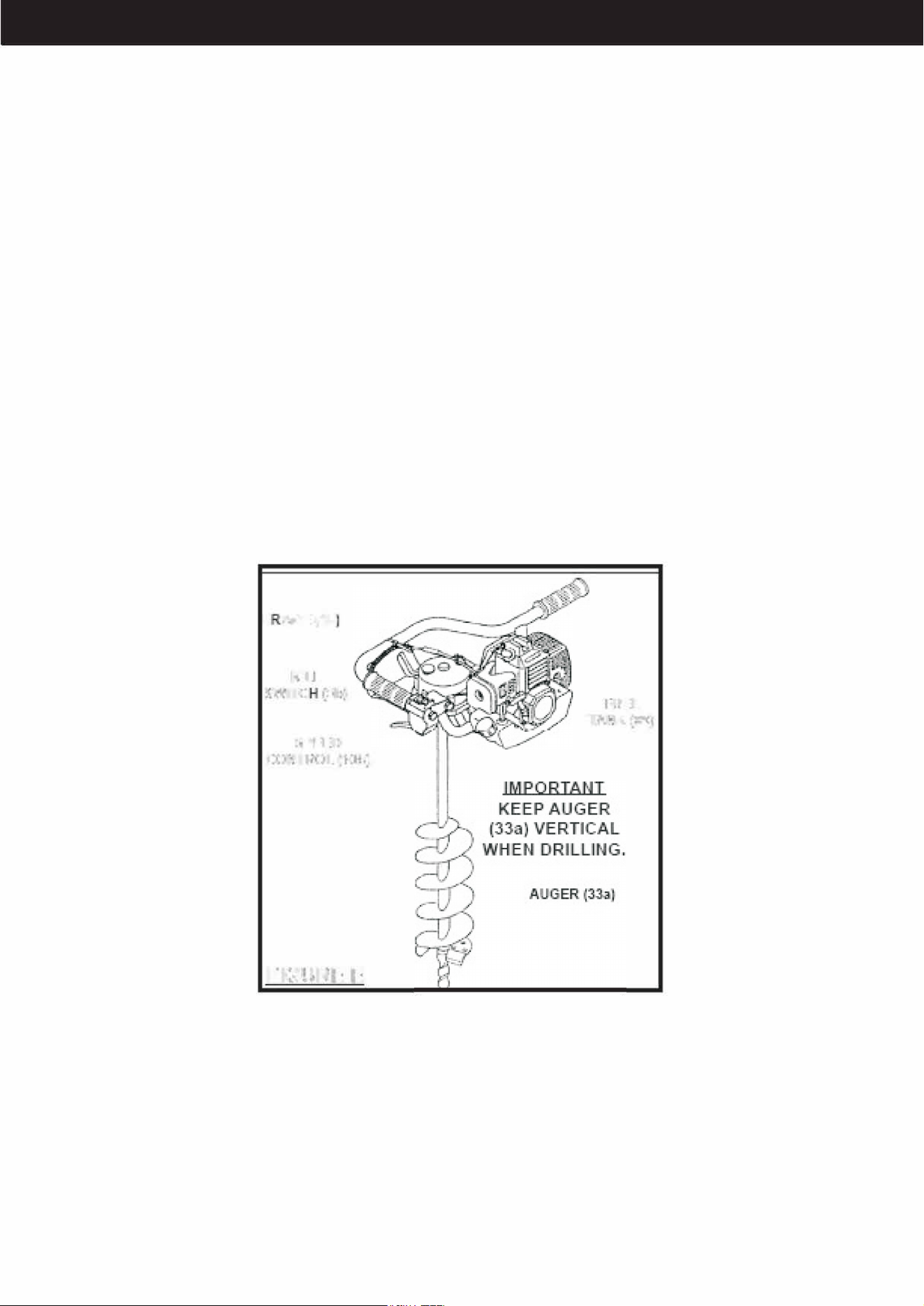
DRILLING A HOLE
1. Stand with a solid stance on stable ground. Brace yourself and maintain a proper grip with both hands on
the Frame (1 b) whenever the engine is running. See Figure E.
2. Accelerate the engine to full throttle just before starting to drill by squeezing the Speed Control (1 Ob) Also,
keep the engine at full throttle the entire time you are drilling, unless a problem arises.
3. Do not attempt to drill at an angle. Always Keep the Auger vertical .
4. Allow the Auger to do most of the work. Exert only minimal pressure downwards. Attempting to force the
drill can cause permanent damage to the unit. Be cautious that the drill will have strong twisting force during
operation.
5. Release the Speed Control as soon as drilling is complete, let the engine idle. Running the Auger Drill at
full throttle without a drilling load can cause unnecessary wear or damage to the unit.
6. After running the drill for an extended period, allow the engine to idle for several minutes to allow heat to
dissipate. This will prevent system parts like the ignition, piston rings, carburetor etc. from being damaged
by overheating. Once you have done this press the Kill Switch (5b) to turn off the engine. See Figure E.
7. Before storing the Auger Drill, make sure to drain all fuel from the fuel tank (89). Failure to do so may
cause old fuel left in the tank to clog the carburetor and prevent start up until it is cleaned out. Once you
have emptied the fuel tank, store the Auger Drill in a clean, dry, safe location. Keep out of reach of children.
See Figure E.
F AME [1b1
Kill.
S,WITC {5b)
.SPBED
CONTROL [1 Ob)1
FIGURE
c
INSPECTION, MAINTENANCE AND CLEANING
IFUH
TANK
1(&!lij
1. WARNING: Remove the Spark Plug (51) and allow the engine to cool completely prior to performing any
service, maintenance or cleaning of the Auger Drill.
2. Before Each Use: Inspect the general condition of the Auger Drill. Check for misalignments or binding of
moving parts, cracked or broken parts, dull or damage parts or any other condition that may affect the safe
operation of the unit. If abnormal noise or vibration occurs, have the problem inspected by a professional
before further use. Do not use the unit if damaged.
6
ASSEMBLY
3. Auger Drill (33a) Maintenance: Using the Auger while that is bent or filled with excessive debris can cause
serious injury. Be sure to replace a defective Auger and always keep the unit clean.
4. Spark Pug (51) Maintenance: The condition of the Spark Plug should be checked ever six months or
every 100 hours of total use. If necessary, clean or replace the Spark Plug. The recommended Spark Plug
replacement type is: L 7T
5. Air Filter (78) Maintenance: The Air Filter should be checked prior to each use of the Auger Drill for debris
and buildup. The Air Filter should be replaced every 3 months or 50 hours of tool use.
6. Gearbox (Sa) Maintenance: The Gearbox should be checked prior to each use for proper quantity. If
necessary, fill the Gearbox with SAE 80-90 weight gear oil. The Gearbox should be filled with clean Gear oil
every 3 months or after 50 hours of tool use.
7. To Clean the Auger Drill: Use a clean cloth and mild detergent to clean the exterior of the engine. DO NOT
use Solvents. Rinse off with caution, DO NOT introduce liquids into the interior of the engine.
CAUTION: All maintenance, service or repairs not mentioned in this manual must only be performed by a
qualified service technician.
Many maintenance procedures, including any not detailed in this manual, will need
to be performed by a qualified technician for safety. If you have any doubts about
your ability to safely service the Auger or engine, have a qualified technician service
the Auger instead.
QUICK START GUIDE
1. Insert the shank of the Bit fully upward into the Transmission Socket on the
bottom of the Auger. Secure the Bit in the Transmission Socket, using the Pin
and R-Pin.
2. Place the Auger on its side with its Bit resting on the ground that is to be
drilled. Press the Primer three or four times.
3. Set the Choke, START if the Engine is cold. RUN if the Engine is warm.
4. Move the Power Switch to the I position. Squeeze and release the Throttle.
5. Grip the Frame firmly with your left hand. Keep all body parts well away from
the Bit. Then, with your right hand, grip the Starter Handle of the Engine gently
until resistance is felt. Allow Cable to retract fully and then pull it quickly. Repeat
until the engine starts.
6. Once the Engine is started, press the Choke down slowly to open it. If the
Engine does not start, press the Primer one more time. Raise the Choke if it is
pressed down, and again attempt to start the Engine.
7. Accelerate the Engine to full throttle just before starting to drill by squeezing
the Throttle. Keep the Engine at full throttle the entire time you are drilling,
unless a problem arises.
8. During drilling, periodically pull Auger up to remove loosened earth. If
loosened earth is allowed to remain in the drilled hole, the Auger will screw into
the earth, become stuck, and twist violently.
7
For more information
on assembling this
product, scan the QR
Code to watch the
instructional video.
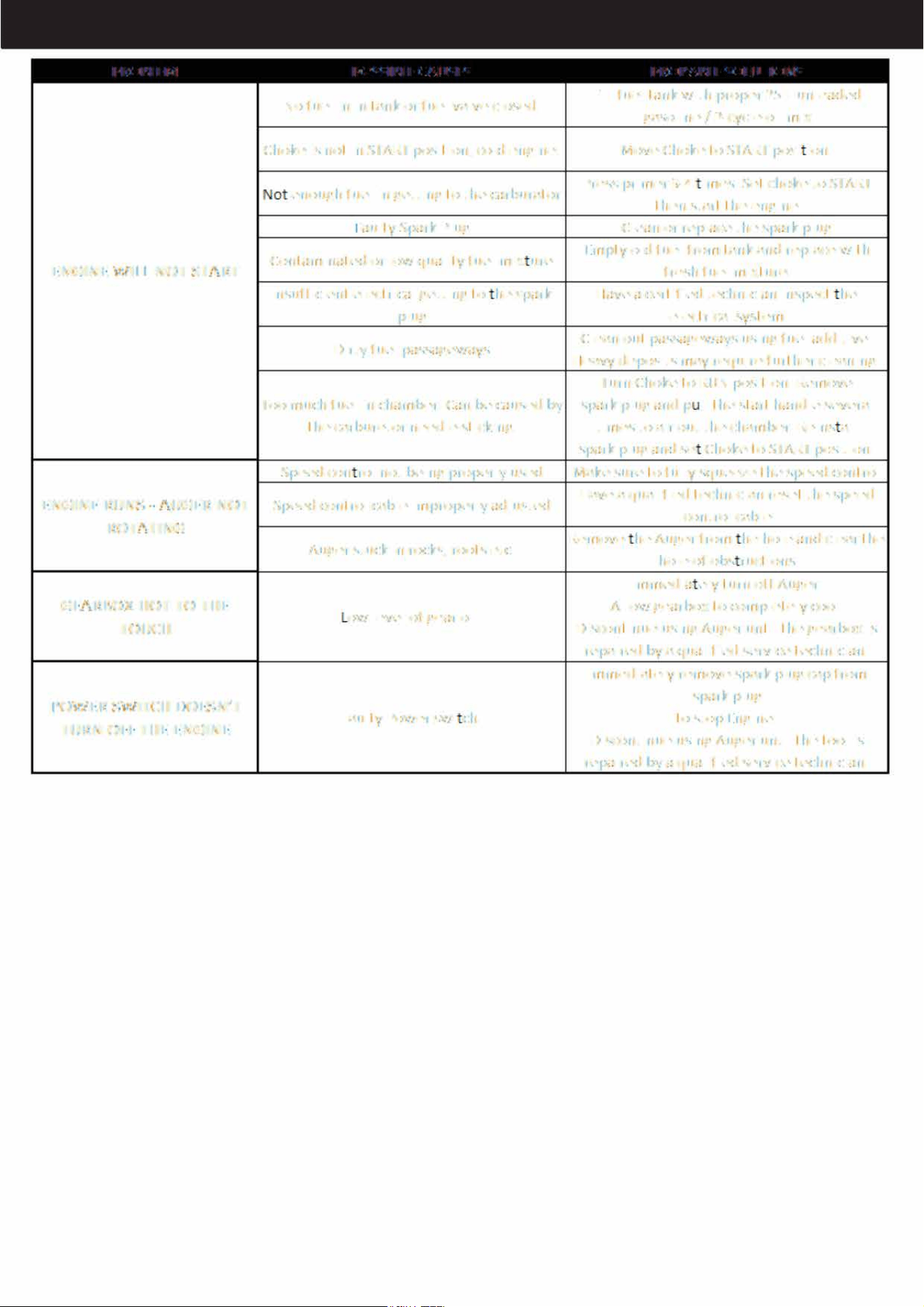
TROUBLESHOOTING
PROBLEM POSSIBLE CAUSES
No fuel in in
tank
or fuel valve closed.
Choke is not in START position, cold engine.
enough fuel is getting to the carburetor
PROBABLE SOLUTIONS
Fill fuel tank with proper 25:1 unleaded
gasoline/ 2-cycle oil mix
Move Choke to START position.
Press primer 3-4 times. Set choke to START
then
start the
engine
Faulty Spark Plug Clean or replace the spark plug
Coliltaminated or low quality fuel mix ure
ENGINE
WILL NOT
START
Empty old fuel from tarik and replace with
fresh fuel mixture.
insufficient electrical getting to
the spark
Have a certified technician inspect he
plug electrical system
Dirty fuel passageways
Clean out passageways using fuel additive.
Heavy deposits may require further cleaning.
Tum Choke to RUN position. Remove
Too much fuel in chamber. Can be caused by spark plug p II the start handle several
the carburetor needle sticking.
Speed 0011 rol not being properly used
ENGINE RUNS - AUGER NOT Speed control cable improperly adjusted
ROTATING
Auger stuck in rocks, roots etc.
GEARBOX HOT TO THE
TOUCH
ow level of
gear
oil.
POWER SWITCH DOESN'T
Faulty Power swi ch.
TURN OFF THE ENGINE
times to air out the chamber. Re install
spark plug and se
Choke to START position.
Make sure to fully squeeze the speed control
Have a qualified technician reset the speed
control cable
Remove he Auger from he hole and clear
the hole
of
obstructions
immediately turn off Auger.
Allow gearbox to completely cool.
Disooritinue using Auger until the gearbox
is
repaired by a qualified service technician.
Immediately remove spark plug cap from
spark plug
to stop Engine.
Discontinue using Auger until the tool is
repaired by a qualified service technician.
8
....--:i·.
-
..
- .1
-• rf
1·
.
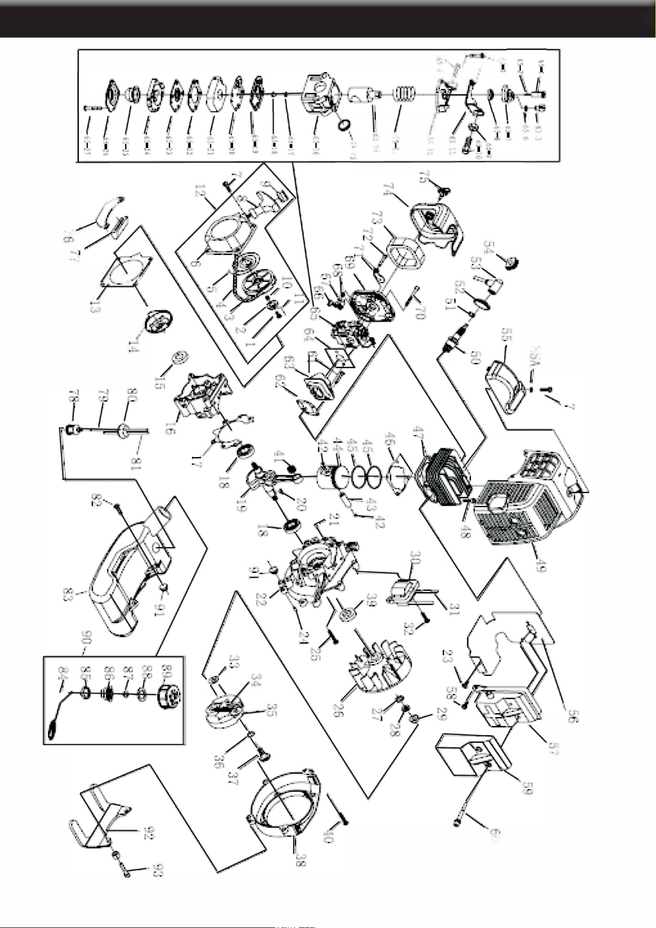
PARTS DIAGRAM
1',n•;
..
t7
9
i t•
I
.
l
,._
,.
't
.,
;-:
I
;f "-I
6
.- (,
C.'1
'I
-..;

PARTS LIST
--:11•.1111,.1,,
1:11•.111, ....
1:11•.11111ahl
11:,.-..•:u•.11■r•l•-
1 Screw 1
25
Screw M5x30
4
48 Screw M5x2.0
4
71 Choker 1
2 Ratchet 1 26 Magneto Rotor Comp 1
49,
Guide Cover Assy 1
72
Screw ST4 2xl2. 1
3 Starter Rope Reel 1 27 Washer B 1 50 Spark Plug 1
73
Filter Net 1
4
Starter rope 1 28 Washer B 1 51 Spring 1 74 Cleaner Outside Cover 1
5 Recoil Spring 1 29
1
NutM8 1 52 Plug cap 1 75 Screw 1
6
Starter Cover Assy
1 30
Ignition Coil Comp
1 53
Cap
1
76 Stand
1
7
Screw M5x
2.0 5,
31
Cord Comp 1
54
Plug 1
77
Rubber Cover 1
8
Start Handle 1 32 Bolt M5xW 2 55 Cover 1 78 Cleaner Gover 1
'9
Ring 1 33 Washer B 2 56 Gasket 1
79,
Fuel Pipe 1
10 Spring 1
34
Spring 1 57 Muffler 1
80
Plug
1
11
Start Pole 2 35 Expander 2 58 ScrewM5xl2 2. 81 Fuel Pipe
1
12 Starter 1 36 Washer 2 59
1
Cover 1 82 Screw M5xl6 2
13
Gasket
1
37 Screw
Pin 2 60 ScrewM6x55
2.
83 Fuel
Tank
1
14
Start Reel 1 38 Fan Cover 1 61
Screw M5x 2.5,
2
84
Chain 1
15
Oil Seal 1 3'9
1
Oil Seal 1 62 Gasket 1
85
End Cover 1
16 Crank Cas,e 1 40 Screw M5x2.5
2
63 Admitting Pipe
1
86 Inside Cover
1
17 Gasket
1 41
Bearing
1
64
Gasket
1
87 Inlet
1
18
Bearing
2
42
Ring 2 65 Carburetor 1
88
Gasket 1
191 Crankshaft 1 43 Piston 1 66 Choker Handle 1 g9, Fuel Tank Lid 1
20 Key 3x5xl3 1
44
Pis on Pin 1 67 Stop Ring 1 90 Lid As.sy 1
21 Pin B4xl!O
2.
45
Pis.ton Ring 2 68 NutM4 1 91 Rllbber Washer 2
22
Crank Cas,e
1
46 Gasket
1 69
1
Cleaner
Inside
Cover
1 92
Stand
1
23 ScrewM4x12 1
47
Cylinder 1
70
ScrewM5x50 2 93 Screw M5x30 2
24 Pin B4xl!O
2
10

OF NOTE
PLEASE READ THE FOLLOWING CAREFULLY
THE MANUFACTURER AND/OR DISTRIBUTOR HAS PROVIDED THE PARTS LIST AND ASSEMBLY
DIAGRAM IN THIS MANUAL AS A REFERENCE TOOL ONLY NEITHER THE MANUFACTURER OR
DISTRIBUTOR MAKES ANY REPRESENTATION OR WARRANTY OF ANY KIND TO THE BUYER THAT
HE OR SHE IS QUALIFIED TO MAKE ANY REPAIRS TO THE PRODUCT, OR THAT HE OR SHE IS
QUALIFIED TO REPLACE ANY PARTS OF THE PRODUCT. IN FACT, THE MANUFACTURER AND/OR
DISTRIBUTOR EXPRESSLY STATES THAT ALL REPAIRS AND PARTS REPLACEMENTS SHOULD BE
UNDERTAKEN BY CERTIFIED AND LICENSEDTECHNICIANS,AND NOTBYTHE BUYER THE BUYER
ASSUMES ALL RISK AND LIABILITY ARISING OUT OF HIS OR HER REPAIRS TO THE ORIGINAL
PRODUCT OR REPLACEMENT PARTS THERETO, OR ARISING OUT OF HIS OR HER INSTALLATION
OF REPLACEMENT PARTS THERETO.
Record Product's Serial Number
Here: _________________ _
Note: If product has no serial number, record month and year of purchase instead.
Note:
Some parts are listed and shown for illustration purposes only and are not available individually
as replacement parts.
SAVE THESE INSTRUCTIONS.
Questions, p ob ems, miss ng parts?
Before returning to your retailer, our exceptional customer service i:s here to
help.
Call Us: 909.628.0880
Email Us: [email protected]
Hours
of O
pe
ra
tio
n: 9am -4pm (Monday - Friday)
PRODUCT MADE IN CHINA
11