
SAVE THIS MANUAL: KEEP THIS MANUAL FOR SAFETY WARNINGS, PRECAUTIONS, ASSEMBLY,
OPERATING, INSPECTION, MAINTENANCE AND CLEANING PROCEDURES. WRITE THE PRODUCT’S
SERIAL NUMBER ON THE BACK OF THE MANUAL NEAR THE ASSEMBLY DIAGRAM (OR MONTH
AND YEAR OF PURCHASE IF PRODUCT HAS NO NUMBER).
OWNER’S MANUAL AND SAFETY INSTRUCTIONS
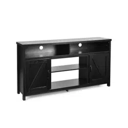
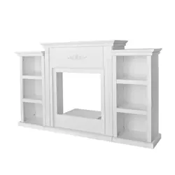
ITEM: 95132 (IVORY) / 95133 (ESPRESSO)
FOR QUESTIONS PLEASE CALL OUR CUSTOMER SUPPORT: (909) 628 0880 MON-FRI 9AM TO 3PM PST
FIREPLACE MANTEL
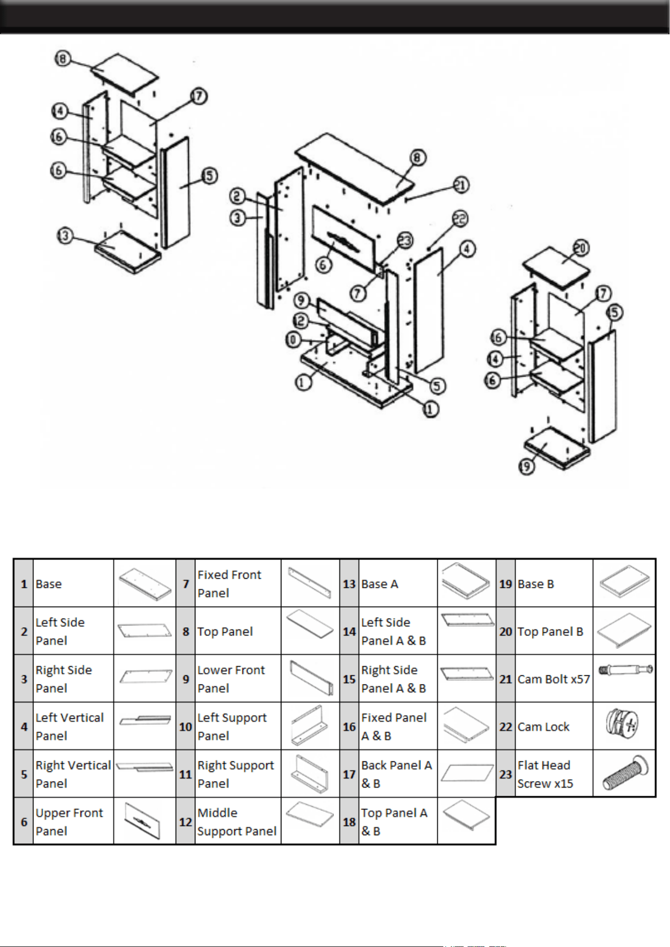
PARTS LIST
1
ASSEMBLY
2
MAIN MANTEL ASSEMBLY
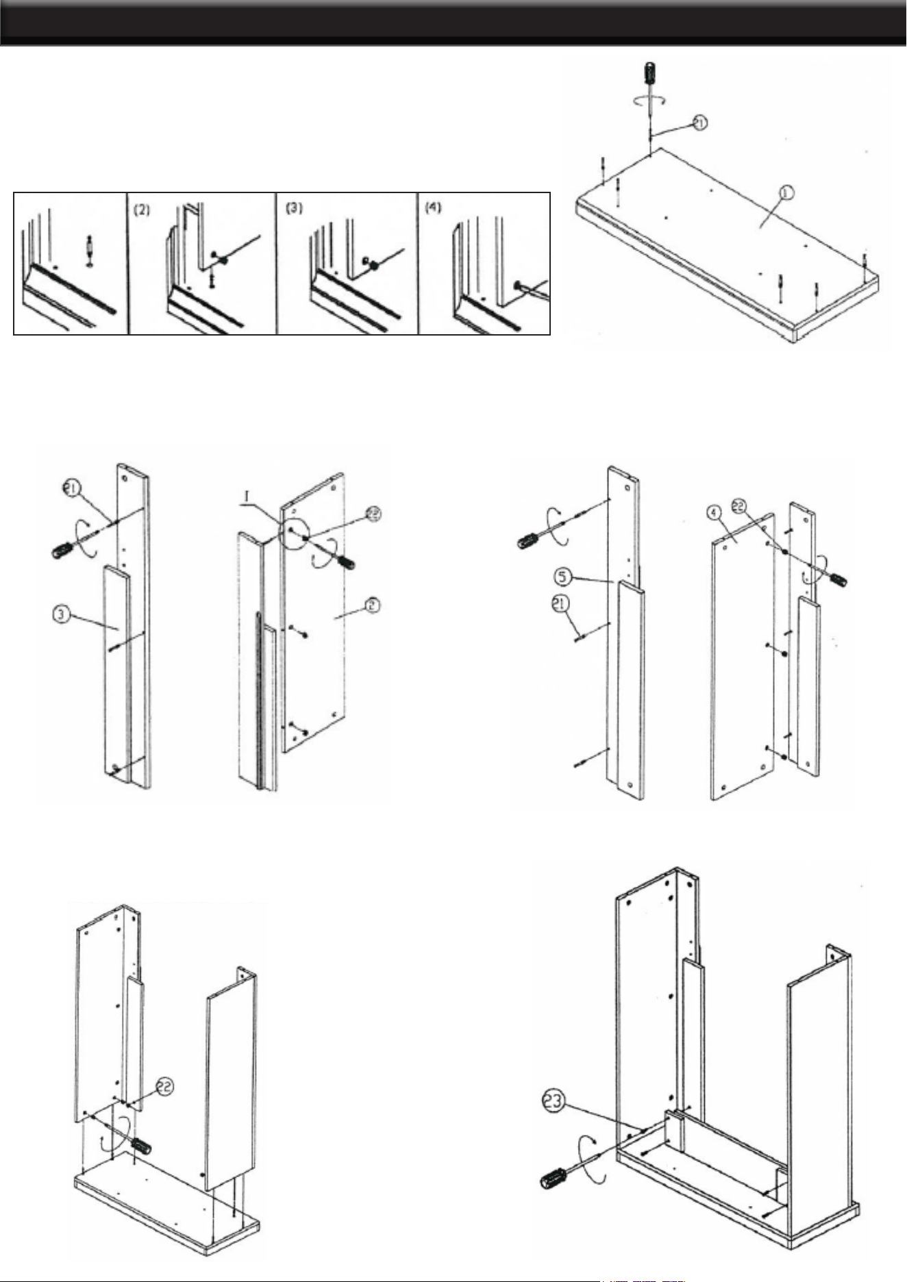
Step 1. Finger tighten cam bolts to help align. Screw cam bolts (21)
into the holes on base (1).
Do not over tighten the cam bolts.
Step 2. Insert the cam bolts (21) into the left vertical
front panel (3). Then insert the cam bolts (21) into
the left side panel (2), tighten by rotating the cam
locks (22) clockwise with a Phillips screwdriver.
Step 3. Insert the cam bolts (21) into the left vertical
front panel (5). Then insert the cam bolts (21) into
the left side panel (4), tighten by rotating the cam
locks (22) clockwise with a Phillips screwdriver.
Step 4. Attach assembled unit on Step 2 and
assemble unit on step 3 to the base on step 1
using cam bolts (21) into the corresponding holes
onto base (1). Tighten by rotating cam locks.
Step 5. Tighten lower front (9) panel to the unit on
step 4 by screw (23)
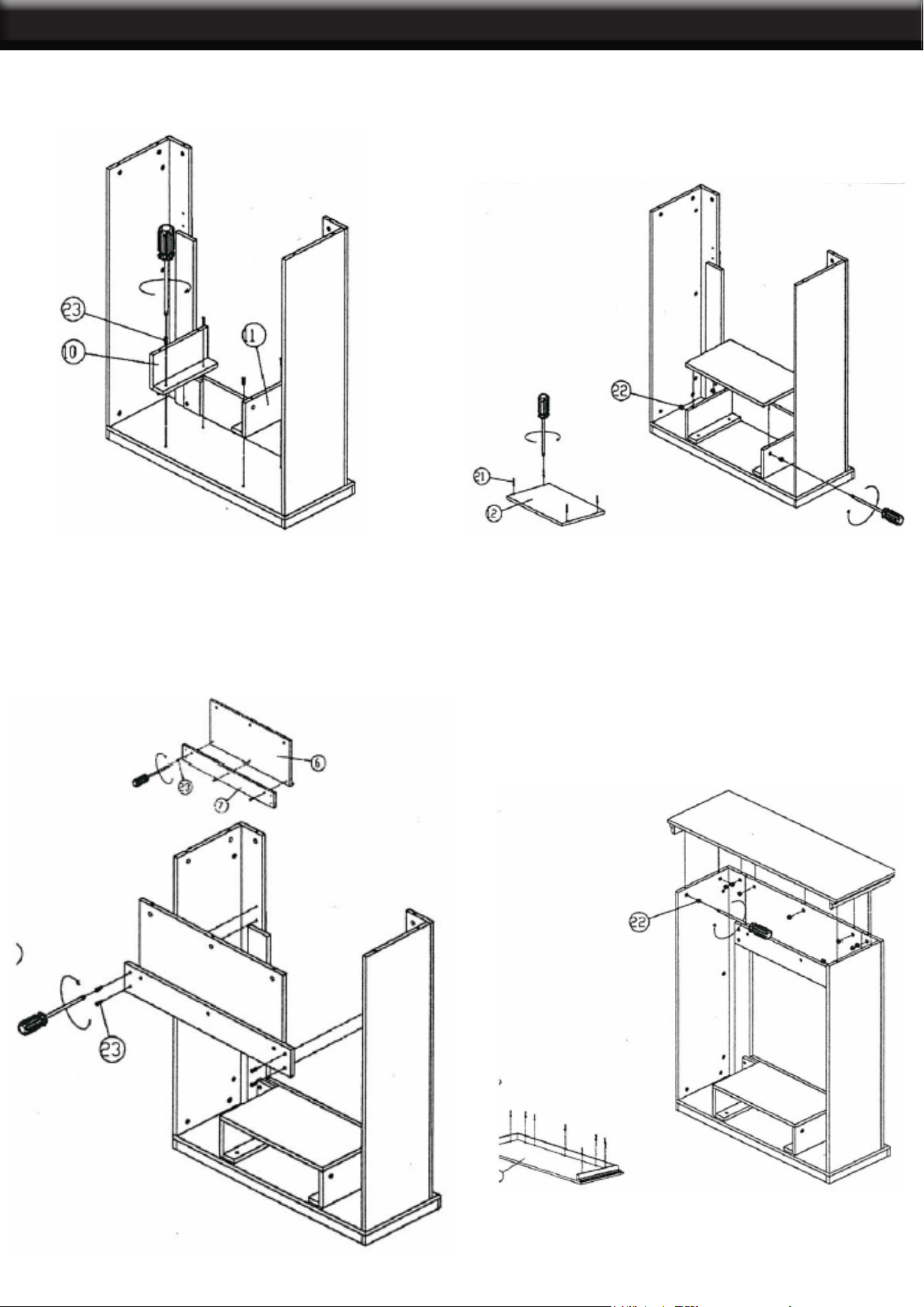
3
ASSEMBLY
Step 6. Screw the left support panel (10) and the
right support pane (11) into the holes on the base.
Step 7. Screw cam bolts (21) into middle support
panel (12). Attach the middle support panel
(12) to the unit on step 6 by cam bolts (21) into
corresponding holes. Tighten by rotating cam
locks with Phillips screwdriver.
Step 8. Tighten the upper front panel (6) to xed
front panel (7) with screws (23). Use screws to
connect the xed front panel (7) by 4 pieces of at
head screws (23).
Step 9. Screw cam bolts (21) into holes on top
panel (8). Attach top panel to assemble unit on
step 8 by cam bolts (21) into corresponding holes
until top panel (8) and assemble. Tight by rotating
cam locks clockwise with screwdriver.
4
ASSEMBLY
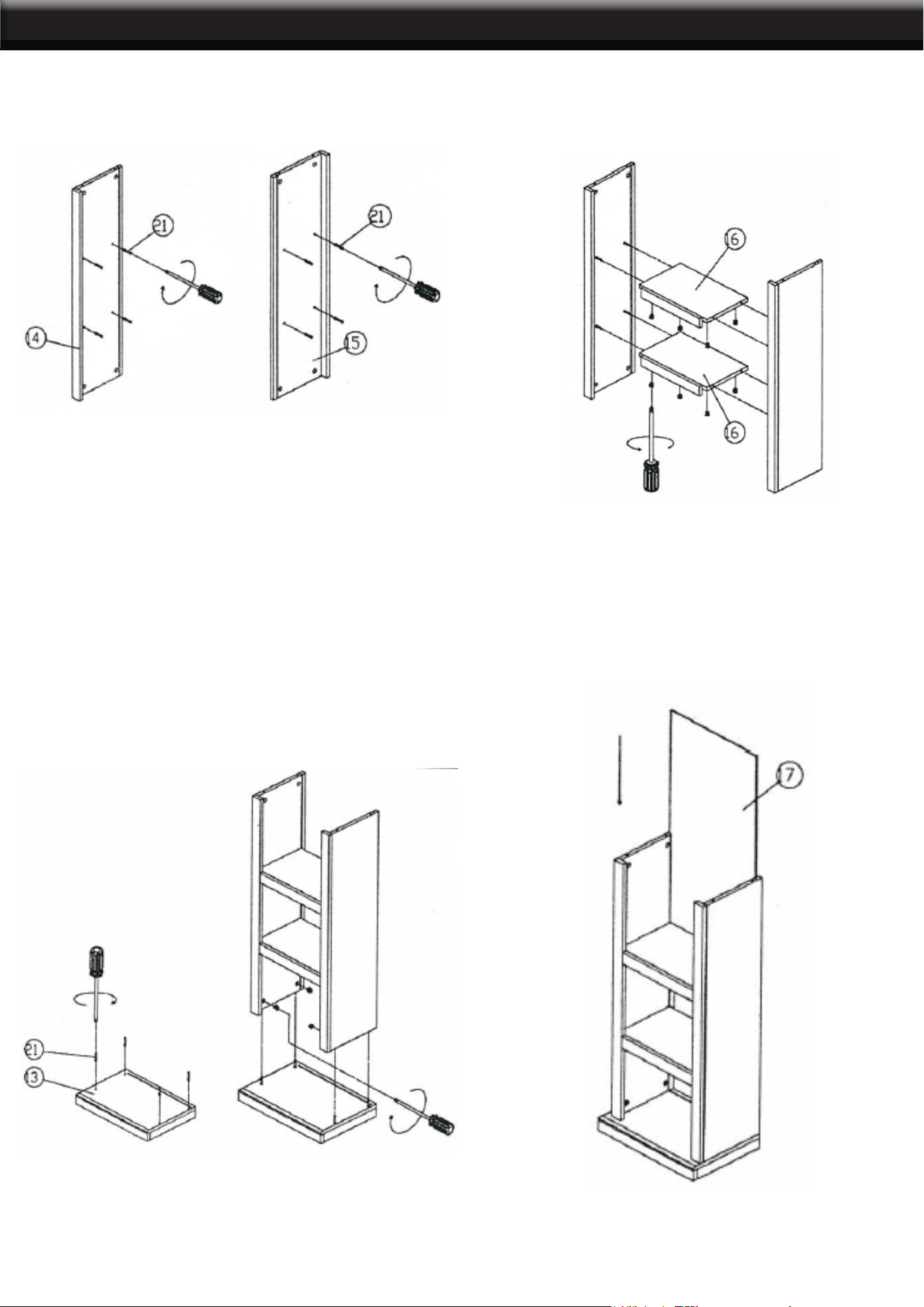
Step 10. Insert cam bolts (21) to the left side panel
(14) and the right side panel (15). Tighten cam
bolts with a screwdriver.
Step 11. Attach assembled unit on step 10 to xed
panel (16) by cam bolts (21) into corresponding
holes into the xed panel. Tight by rotating cam
locks clockwise with screwdriver.
Step 12. Screw cam bolts (21) into holes on base
(18). Attach base to assembled unit on step 11 by
cam bolts (21) into corresponding holes until base
and assembled unit on step 11. Tighten by rotating
cam locks with Phillips screwdriver.
Step 13. Insert the back panel (17) into the
assembled unit on step 12.
5
INFORMATION
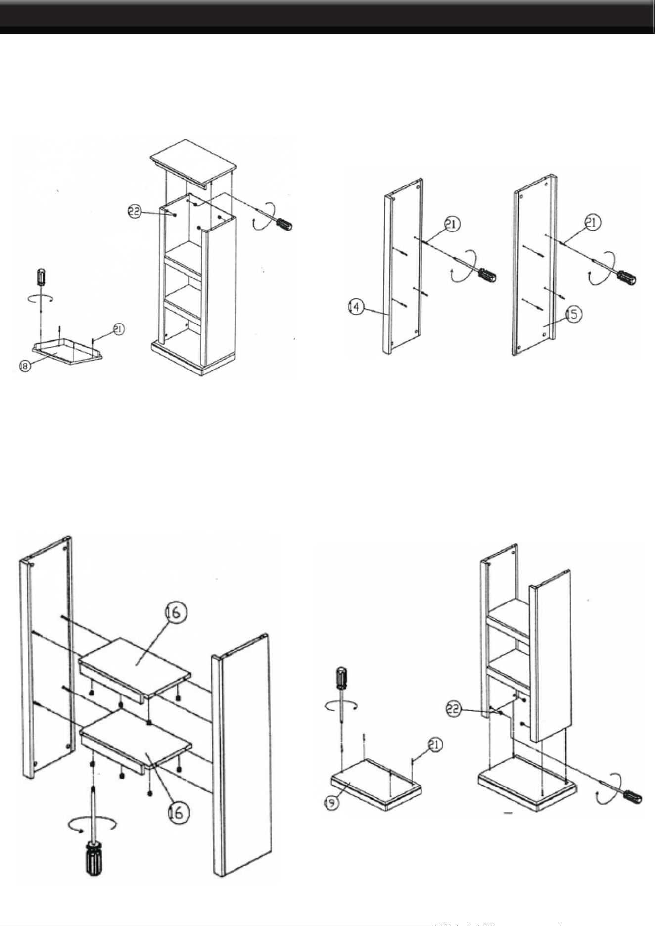
Step 14. Screw cam bolts (21) into holes on top
panel (18). Attach op panel to assembled unit on
step 13 by cam bolts (21) into corresponding holes
into top panel (18). Assemble unit until step 13
meet. Tighten by rotating cam locks with Phillips
screwdriver.
Step 15. Insert the cam bolts (21) to the left side
panel (14) and the right side panel (15). Tighten by
rotating cam locks with screwdriver.
Step 16. Attach assembled unit on step 10 to xed
panel (16) by cam bolts (21) into corresponding
holes into the xed panel. Tighten by rotating cam
locks clockwise with screwdriver.
Step 17. Screw cam bolts (21) into the holes on base
(19). Attach base to assemble unit to step (16) by
cam bolts (21) into corresponding holes until base
and assemble until unit on step 16 meet up. Tighten
by rotating cam locks with screwdriver.
6
ASSEMBLE
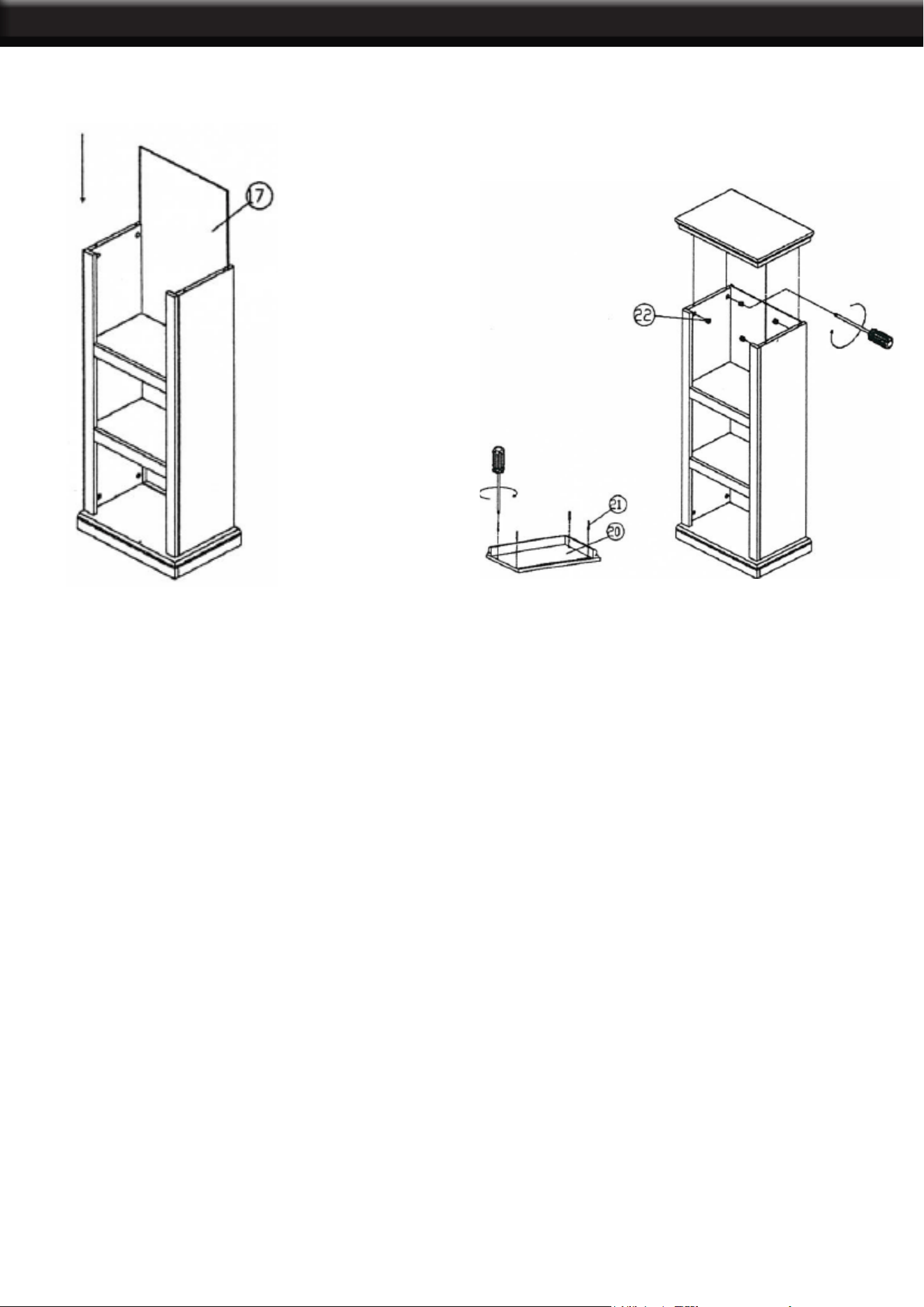
Step 18. Insert the back panel (17) into the
assembled unit on step 17.
Step 19. Screw cam bolts (21) into the holes on top
panel (20). Attach the top panel to the assembled
unit on step 18 by cam bolts into corresponding
holes until top panel (20) and assemble until unit on
step 18 meet up.
THE MANUFACTURER AND/OR DISTRIBUTOR HAS PROVIDED THE PARTS LIST AND ASSEMBLY
DIAGRAM IN THIS MANUAL AS A REFERENCE TOOL ONLY. NEITHER THE MANUFACTURER OR
DISTRIBUTOR MAKES ANY REPRESENTATION OR WARRANTY OF ANY KIND TO THE BUYER THAT
HE OR SHE IS QUALIFIED TO MAKE ANY REPAIRS TO THE PRODUCT, OR THAT HE OR SHE IS
QUALIFIED TO REPLACE ANY PARTS OF THE PRODUCT. IN FACT, THE MANUFACTURER AND/OR
DISTRIBUTOR EXPRESSLY STATES THAT ALL REPAIRS AND PARTS REPLACEMENTS SHOULD BE
UNDERTAKEN BY CERTIFIED AND LICENSED TECHNICIANS, AND NOT BY THE BUYER. THE BUYER
ASSUMES ALL RISK AND LIABILITY ARISING OUT OF HIS OR HER REPAIRS TO THE ORIGINAL
PRODUCT OR REPLACEMENT PARTS THERETO, OR ARISING OUT OF HIS OR HER INSTALLATION
OF REPLACEMENT PARTS THERETO.
Record Product’s Serial Number Here:
Note: If product has no serial number, record month and year of purchase instead.
Note: Some parts are listed and shown for illustration purposes only and are not available individually
as replacement parts.
PLEASE READ THE FOLLOWING CAREFULLY
19
DISCLAIMER
PRODUCT MADE IN CHINA