
48-59-1804
M18
™
and M12
™
Gangbox Rapid Charger
April 2025
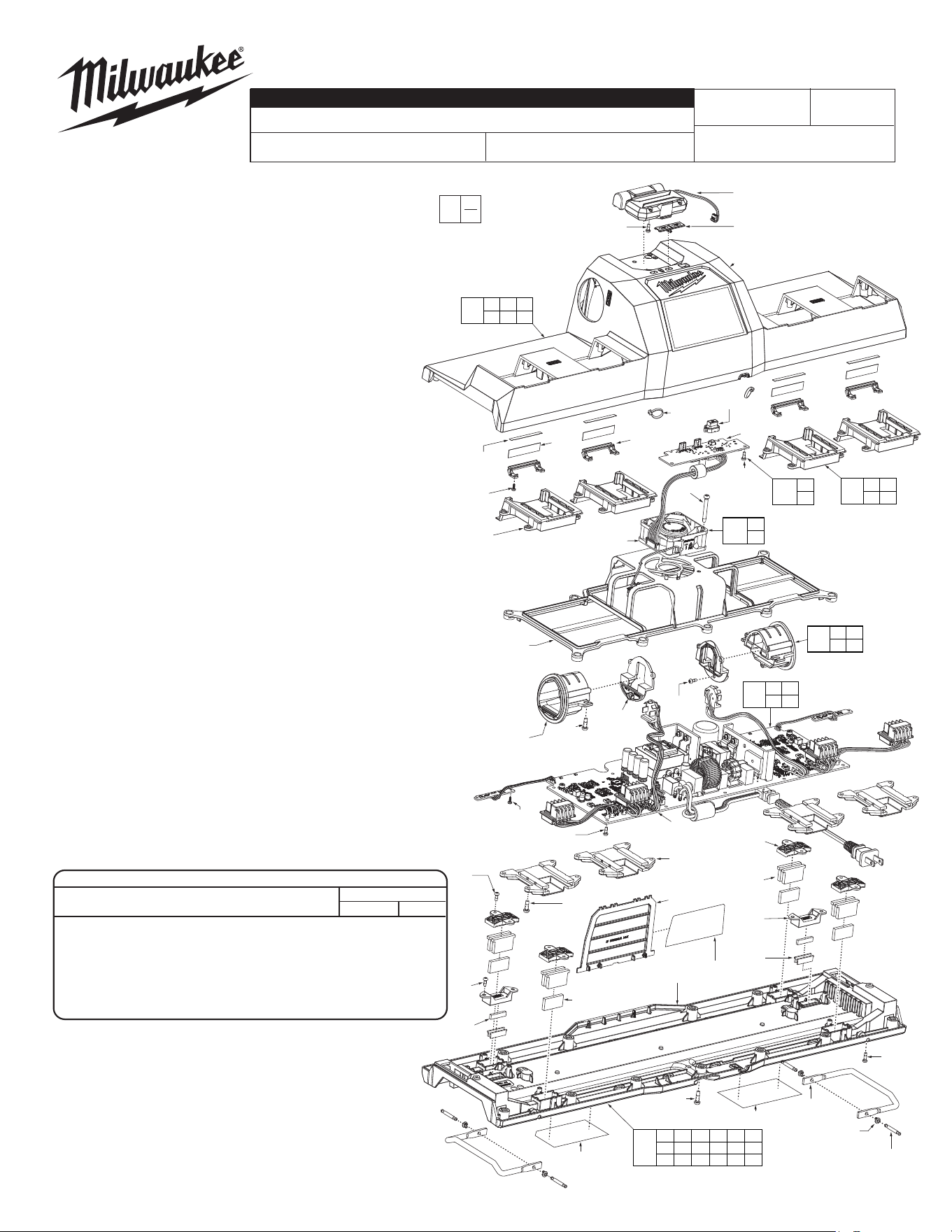
FIG. PART NO. DESCRIPTION OF PART NO. REQ.
1 23-94-5385 LED Work Light Assembly (1)
2 31-15-2220 Dual USB-C Cover (1)
3 --------------- Top Housing (1)
4 05-81-1195 M3 x 8mm Pan Hd. T-10 Screw (33)
5 --------------- Battery Indicator Lens (4)
6 05-88-0083 M2.2 x .98 PT T-8 Screw (12)
7 --------------- Rubber Button (1)
8 --------------- PCB Subsystem Board Assembly (1)
10 --------------- M18 Interface Rail (4)
11 06-82-0088 M4 x 1.411 Pan Hd. T-20 Screw (2)
12 --------------- Fan Assembly (1)
13 43-40-0510 Main PCBA Frame (1)
14 --------------- M12 Interface (2)
15 --------------- M12 Interface Cover (2)
16 --------------- Main PCBA Assembly (1)
17 --------------- M18 Interface Back Plate (4)
18 06-82-0032 M4 x 12mm Pan Hd. T-20 Screw (20)
19 --------------- Large Magnet Bracket (4)
20 --------------- Large Magnet (4)
21 --------------- Large Billet (8)
22 31-50-2595 Top Housing Plate (1)
23 --------------- Small Magnet Bracket (2)
24 --------------- Small Magnet (2)
25 --------------- Small Billet (4)
26 --------------- Bottom Housing (1)
27 --------------- Lever Pin (4)
28 --------------- Lever (2)
29 05-74-0226 M4 x 14mm T-20 Pan Hd. Blk Screw (13)
30 --------------- Zip Tie (2)
31 10-22-1760 Warning Label (Fr/Sp) (1)
32 12-20-9690 Service Nameplate (1)
33 10-22-1765 Warning Label (English) (1)
34 --------------- Small Shading Label (4)
35 --------------- Large Shading Label (4)
36 --------------- Friction Grommet (4)
37 06-82-3002 M3 x 10mm Pan Hd. T-10 Screw (2)
40 14-46-9766 Top Housing Kit (1)
41 14-46-9767 Subsystem Board Kit (1)
42 14-46-9768 Fan Kit (1)
43 14-46-9769 M18 Interface Rails Kit (1)
44 14-46-9770 M12 Interface Kit (1)
45 14-46-9771 PCBA Board Kit (1)
46 14-46-9772 Bottom Housing Kit (1)
FIGS. NOTES
31-35 A clean, dry surface is essential for proper performance for
any adhesive system. The area intended for application
of any adhesive label or nameplate must be prepared by
cleaning with isopropyl alcohol. The solvent is to be applied
with a clean, lint free applicator and the surface allowed to
dry before applying the label or nameplate.
PN0004150
REVISED BULLETIN
SERVICE PARTS LIST
BULLETIN NO.
WIRING INSTRUCTION
DATE
CATALOG NO.
SPECIFY CATALOG NO. AND SERIAL NO. WHEN ORDERING PARTS
EXAMPLE:
Component Parts
(Small #) Are Included
When Ordering The
Assembly (Large #).
0
00
P97A
MILWAUKEE TOOL
l
www.milwaukeetool.com
13135 W. LISBON RD., BROOKFIELD, WI 53005
Drwg. 1
TORQUE SPECIFICATIONS
SEAT TORQUE
FIG. PART NO. WHERE USED (kgf-cm) (lb-in)
4 05-81-1195
Work Light/Magnets/M12 Interface
6-8 5-7
6 05-88-0083 Battery Indicator Lens/PCBA 1.5-2.5 1.3-2.2
11 06-82-0088 Fan Assy. 9-11 8-10
18 06-82-0032 M12/M18 Interface 10.3-11.7 8.9-10.2
29 05-74-0226 Bottom Housing 9-12 8-10
37 06-82-3002 Bottom Housing 6-8 5-7
SERIAL NO.
See Page 2
1
24
(4x)
4
(2x)
11
(2x)
30
(2x)
7
8
12
35
(4x)
34
(4x)
10
(4x)
13
14
(2x)
6
(4x)
18
(4x)
15
(2x)
4
(6x)
16
17
(4x)
19
(4x)
21
(8x)
20
(4x)
23
(2x)
25
(4x)
22
26
29
(13x)
27
(4x)
36
(4x)
37
(2x)
28
(2x)
31
32
6
(8x)
18
(16x)
4
(8x)
4
(9x)
4
(4x)
24
(2x)
3
5
(4x)
3 4 5
6 7 30
40
4
8
41
11
12
42
10 17
18
43
4 14
15 18
44
4 6
16
45
4 19 20 21 22 23
24 25 26 27 28 29
31 32 36 37
46
33
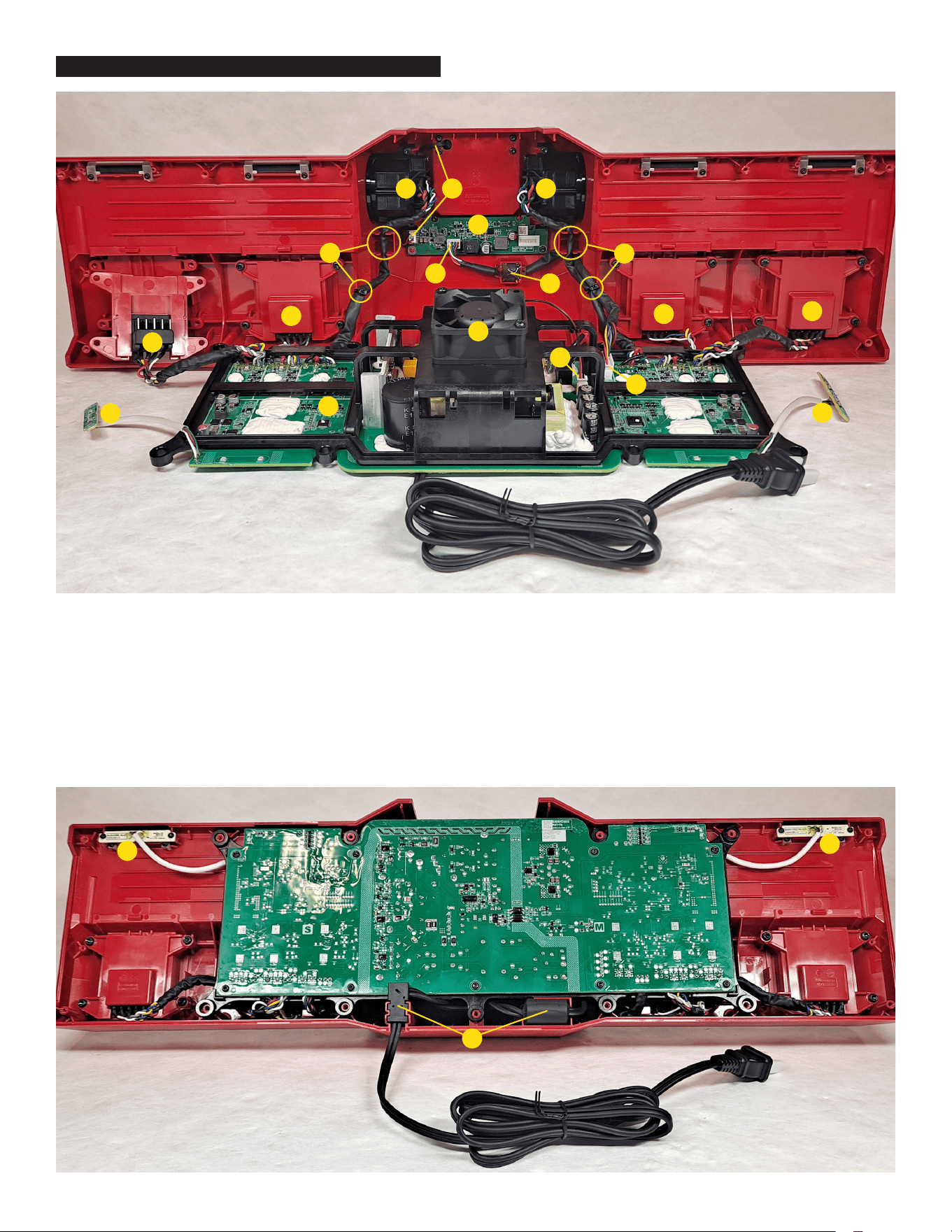
1. Main PCBA Assembly
2. Fan Assembly
3. Fan Assembly to PCBA Connector
4. Subsystem Board Assembly
5. LED Work Light Assembly to Subsystem Board Connector
6. PCBA to Subsystem Board Connector
7. Ferrite Bead - Apply hot glue to hold in place
8. Subsystem Board to PCBA Connector
1. Main PCBA Assembly
2. Fan Assembly
3. Fan Assembly to PCBA Connector
4. Subsystem Board Assembly
5. LED Work Light Assembly / Wires
6. PCBA to Subsystem Board Connector
7. Ferrite Bead - Apply hot glue to hold in place
8. Subsystem Board to PCBA Connector
9. M12 Terminal Block / Interface
10. M18 Terminal Block / Interface Rails
11. Battery Indicator
12. M12 Interface Wires - Add zip tie and route
within traps as shown
13. AC Power Cord - Place cord and ferrite bead
into channels
10
11
13
11
11
11
10
12
10
10
2
3
5
6
7
4
1
9 9
8
12
M18 & M12 Gangbox Rapid Charger Wiring