INHABIT™ ENERGY INSTALLATION GUIDE 1
INSTALLATION GUIDE
Inhab
™
Energy
Smart Home
Energy Monitor
usa.siemens.com/InhabEM
2 INHAB™ ENERGY INSTALLATION GUIDE
Safety Alert Symbol
This is the safety alert symbol. It is used to alert you to potential personal
injury hazards. Obey all safety messages that accompany this symbol to
avoid possible injury or death.
Safety information
WARNING
The Siemens Inhab Energy requires installing transformers inside a
home’s electrical panel and working around dangerous voltage that
could lead to injury or death. The installation should be performed by
qualified personnel only such as a licensed electrician or other
qualified professional in accordance with the regional electrical code
where it is being installed.
Improper installation or use of the equipment can be dangerous or
even fatal. In no event shall Siemens be liable to you or any third
party for any damages, either direct or indirect, arising from or
related to any personal injury as a result of your failure to follow the
safety information and instructions in this Installation Guide.
DANGER
Hazardous Voltage will cause death or serious injury.
INHAB™ ENERGY INSTALLATION GUIDE 3
Safety information
WARNING
• Turn off and lock out all power supplying this device before
working on this device. Replace all covers before power
supplying this device is turned on. Wear protective eyewear
and protective gloves before attempting to inspect the Inhab
Energy system. Ensure no wiring for voltage measurement,
current measurement, power, or data are frayed or have
exposed conductors. Ensure there are no cracks, breaks, or
other defects in the enclosure of the Inhab Energy or CTs.
• If you believe any of the Siemens Inhab Energy components
may have been damaged, do not attempt to use them. Contact
support at 1-800-241-4453 immediately.
• Do not use the Siemens Inhab Energy in any manner other than
specified in this installation guide, otherwise, the protection
provided by the equipment may be impaired.
• Do not attempt to open, disassemble, or repair any of the
components of the Siemens Inhab Energy.
• Do not install the Siemens Inhab Energy in environments with
explosive gas or vapors; nor in damp or wet environments; nor in
direct sunlight; nor where temperatures are consistently below
-40° F (-40° C) or above 122° F (50° C).
• Ensure the Siemens Inhab Energy does not have power during
any handling, including installation and disassembly.
• Do not perform any maintenance, service, or cleaning of the
Inhab Energy after installation. Contact customer service for
support.
• The Siemens Inhab Energy should only be used with Listed
Energy-Monitoring Current Transformers.
• Basic Insulation, use CTs only on insulated conductor, secured
from contacting live parts.
• To reduce risk of electric shock, always open or disconnect
circuits from the power-distribution system (or service) of a
building before installing or servicing current transformers.
• The Siemens Inhab Energy should be wired to power using
16AWG, 600V, UL1015, 105° C (or higher) copper-only wires
• It is recommended that the Siemens Inhab Energy be wired to
the breaker closest to the device.

4 INHAB™ ENERGY INSTALLATION GUIDE
Safety information
WARNING
• Do not position the Siemens Inhab Energy so that it is difficult to
operate disconnecting devices or breakers.
• Do not use 3rd party accessories or Current Transformers (CTs) with
the Siemens Inhab Energy. The Inhab Energy and CTs are
customized and integrated. Third party accessories or CTs may
compromise the data accuracy and equipment safety.
• The current transformers may not be installed in equipment where
they exceed 75 percent of the wiring space of any cross-sectional
area within the equipment
• Restrict installation of current transformers in an area where it
would block ventilation openings.
• Restrict installation of current transformers in an area of breaker
venting. Do not install the Siemens Inhab Energy Monitor in any
area where breaker arc venting exhaust gasses could be re-directed
as a result of submetering equipment installation.
• The Siemens Inhab Energy is not suitable for Class 2 wiring
methods and not intended for connection to Class 2 equipment.
(Refer to NEC 2023, Section 725.)
• Secure current transformers and route conductors so that the
conductors do not directly contact live terminals or buses.
• The Siemens Inhab Energy shall not be mounted within 50.8 mm
(2 in) of any live parts including primary conductors, primary
terminals, and primary lugs; but excluding insulated cables. It’s
acceptable for the Inhab Energy to be mounted to the grounded
panel box and near the neutral/ground bus bars. The Inhab
Energy employs Class I wiring allowing its wires to safely coexist
with all other wires in the panel.
• If the Siemens Inhab Energy Monitor is attached to the enclosure,
it shall not contact the panel interior insulation such as the material
that separates the GND and LIVE bus bars.
• Siemens Inhab Energy Monitor mounting provisions shall not be
attached to any energized part.
• Voltage sensing and power supply connections to the primary
voltage shall have overcurrent protection through connection to a
breaker/MCB.
• Do not use aluminum wire with the Inhab product.
• Do not install the Siemens Inhab Energy in electrical panels installed
in outdoor environments.
INHAB™ ENERGY INSTALLATION GUIDE 5
Before you get started
The Siemens Inhab Energy is installed in a home’s electrical panel. It will be
necessary to turn off power supplying the home’s electrical panel. If the
home’s electrical panel is service equipment, the main breaker should be set
to the off position. Please note, setting the main breaker to the off position
will only shut off power to the home; the cables feeding the panel will remain
energized. The following may help with safe installation.
• Installation should be performed by a qualified personnel only such as a licensed
electrician or other qualified professional
• Install in accordance with the regional electrical code where it is being installed
• Ensure that the product specifications of the Inhab Energy are compatible with
the system and the panel type where it is being installed.
• Identify the location of service disconnect. It may be outside of the panel.
• Ensure the work environment is clean with additional lighting available.
• Identify empty breakers or breakers that can be tapped for voltage monitoring.
The number required corresponds to the system phases.
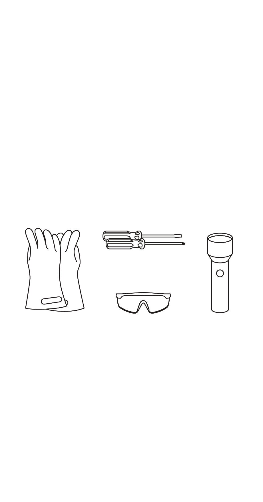
• The following items are recommended:
Insulated gloves Protective eyewear
Alternative
light source
Phillips and flathead
screwdrivers
6 INHAB™ ENERGY INSTALLATION GUIDE
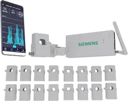
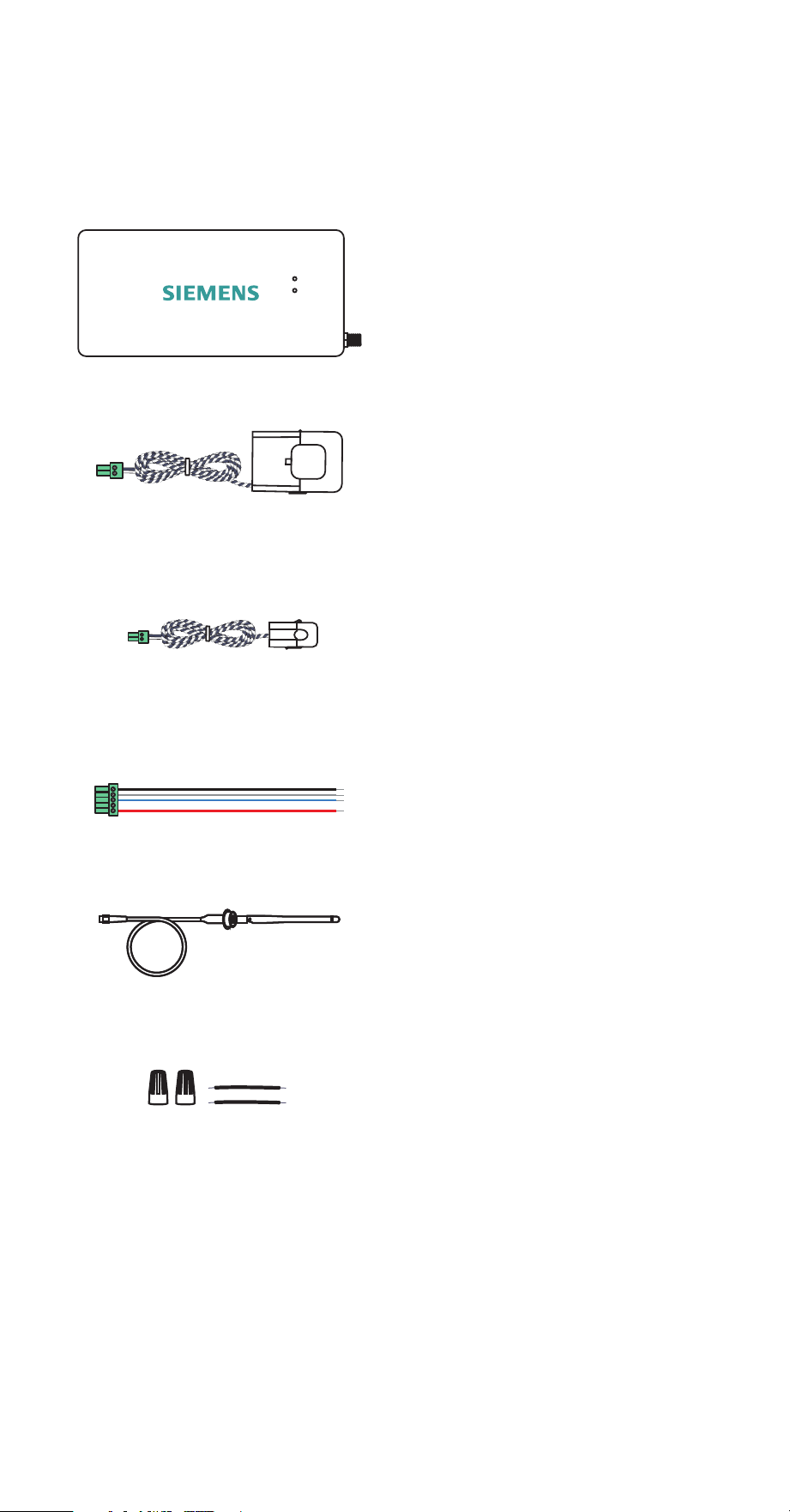
What’s in the box
The Siemens Inhab Energy contains the following items. If any of these items are
missing or if you believe they’ve been damaged, contact support immediately.
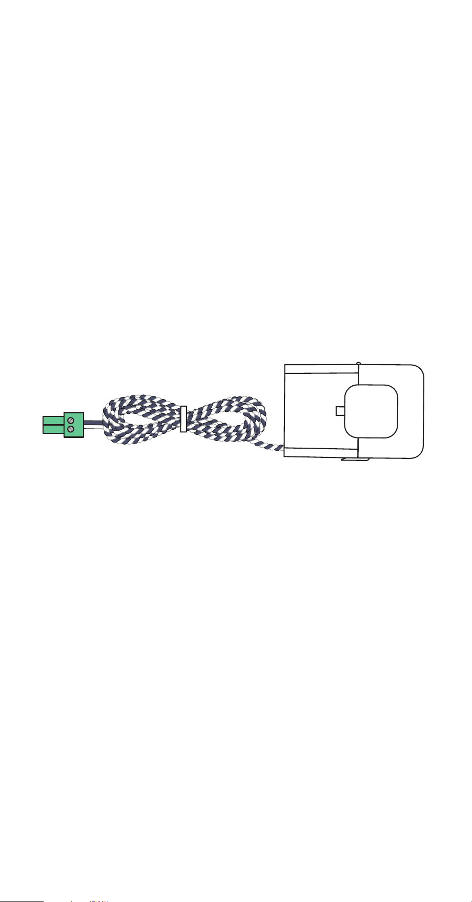
Inhab Energy monitor
2 Main 200A CTs with 22 AWG wire and
5mm screw terminal plugs
16 Branch 50A CTs with 22 AWG wire and
3.8mm screw terminal plugs
Wire harness with 7.6mm screw terminal
plugs and 4x16AWG wire leads
WiFi antenna assembly
2 wire nuts and two 14 AWG, 600V
splicing wires
INHAB™ ENERGY INSTALLATION GUIDE 7
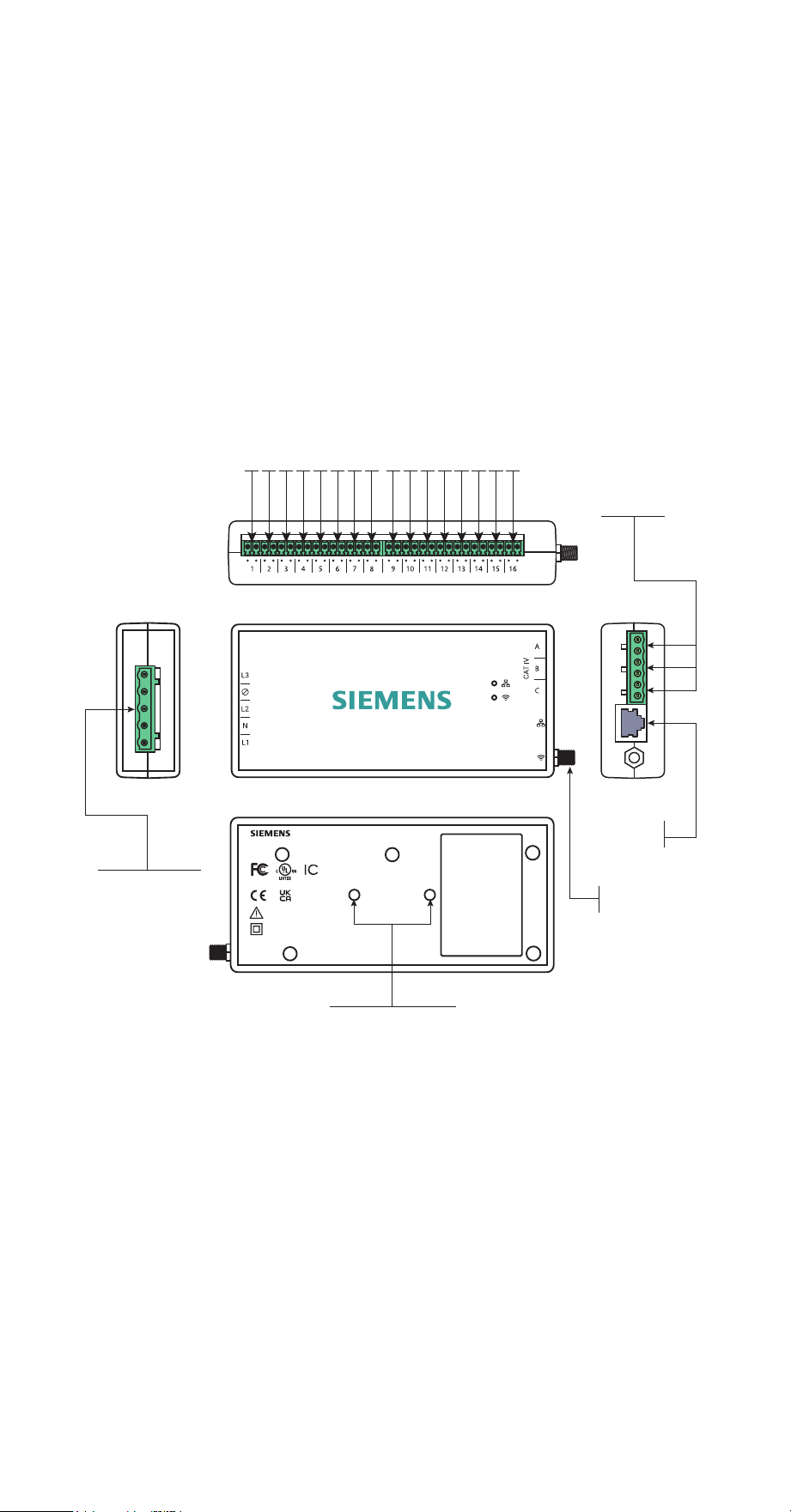
Energy monitor connections
The energy monitor is the hub of the Siemens Inhab Energy. The screw terminal
port for the wiring harness is located on the left-hand side of the monitor. The
screw terminal ports across the top of the monitor are the inputs for the 50A Branch
Current Transformers (CTs) (the bundle may have come with 8 or 16 CTs, or none at
all). The A, B, and C screw terminal ports on the right side of the monitor are the
inputs for the 200A Main CTs (the bundle may have shipped with two or three). The
RJ45 LAN port and coaxial connector for the WiFi antenna cable are also on the
right hand side of the monitor. All of the ports are clearly labeled on the energy
monitor.
WiFi
connector
RJ45
LAN port
top
frontleft
right
back
1 2 3 4 5 6 7 8 9 10 1112 13 14 15 16
50A CT 3.8mm screw terminal ports
200A CT screw
5mm terminal
ports (A,B,C)
Wiring harness
7.6mm screw
terminal port
M3 DIN rail mount
CAUTION / ATTENTION
Risk of electric shock
Review the installation guide.
Risque de choc electrique
Lisez le guide d'installation.
~100-240VAC L-N 1Ø/3Ø (Wye only)
50/60Hz, 0.041A, CAT III
Energy Monitor
E535044
IC: 28084-EMV3A
FCC ID:
2AS6P-EMV3A
Model: EMV3A
Inhab
TM
Energy | Model: INHEM100
3617 Parkway Ln, Peachtree Corners, GA 30092 | Made In India
RJ45
LAN port

8 INHAB™ ENERGY INSTALLATION GUIDE
Step 1: Get the app
Use the camera on your phone to scan the unique QR code located either on the
back of the Inhab Energy monitor or on the Getting Started Guide included in the
box. This QR code will take you to the Siemens Inhab Energy Monitoring home
page, where you can download the Siemens Inhab Energy app onto a phone or
tablet from the Apple App Store or Google Play and start the Inhab Energy setup
process. Once the app is downloaded, you’ll be prompted to create an account if
you don’t have one.
Also, if you plan to connect the Inhab Energy to the internet via Wi-Fi, this is a great
time to use a phone to check the signal strength of the Wi-Fi network next to the
electrical panel in the home. Low/no signal may require a Wi-Fi extender or an
ethernet connection for the Inhab Energy to work properly.
INHAB™ ENERGY INSTALLATION GUIDE 9
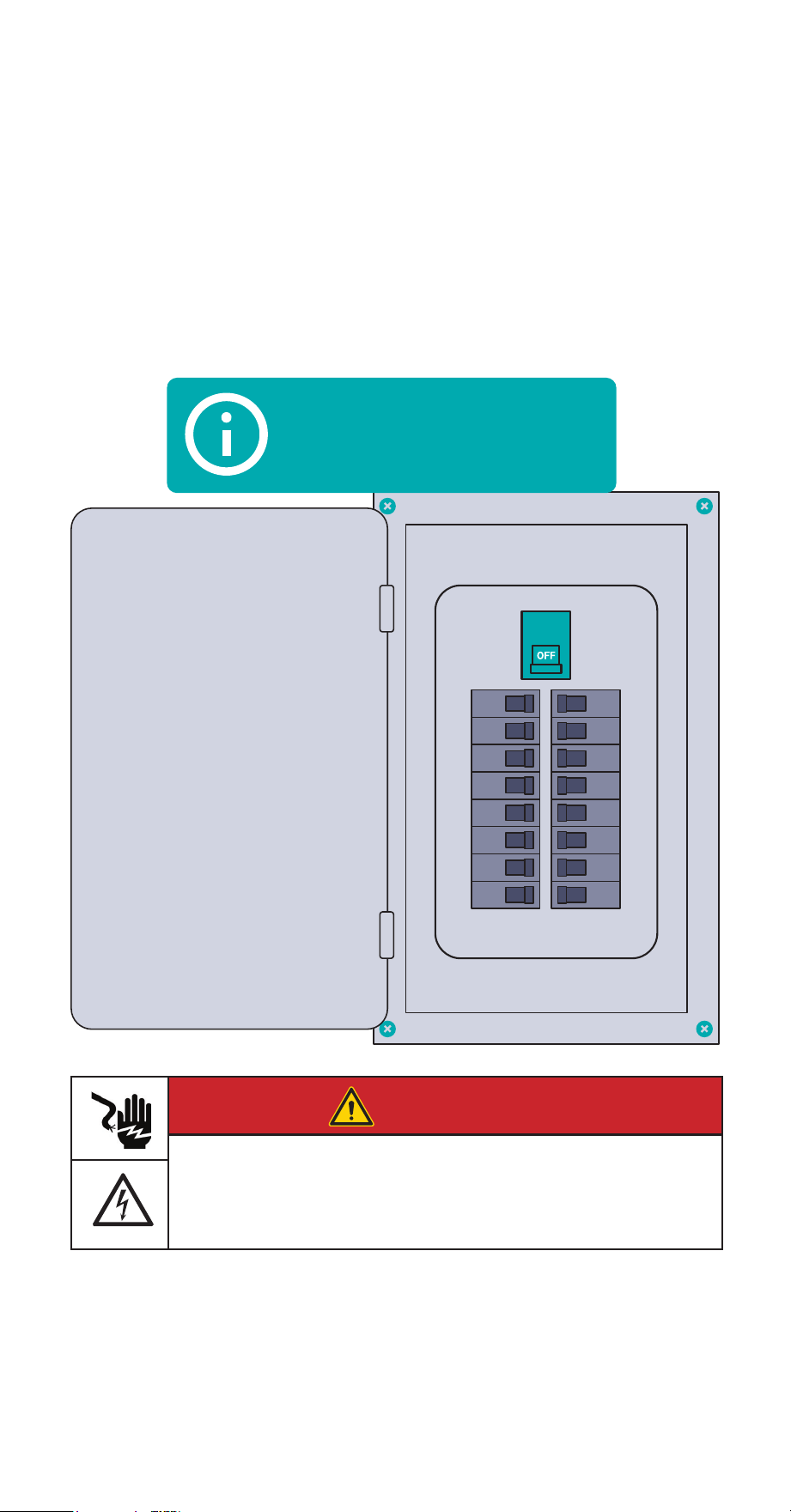
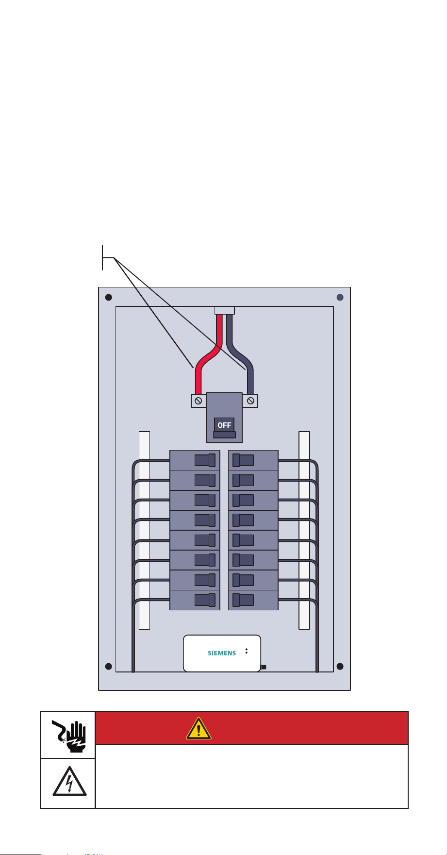
Step 2: Turn off the main
breaker and remove the cover
First, turn service disconnects and/or main breakers feeding the panel into the OFF
position. Note that these may be located outside of the panel in which you’re
installing the Inhab Energy. Next, remove any screws holding the cover to the panel
and remove the cover to access the circuit breakers and service entrance wires to
the load center. Service entrance wires are energized!
Service disconnect may
be located outside of
the panel
DANGER
Hazardous Voltage
Will cause death or serious injury.
Turn off and lock out all power supplying this device before working on
this device. Replace all covers before power supplying this device is
turned on.
10 INHAB™ ENERGY INSTALLATION GUIDE
Step 3: Find a place
for the monitor
Locate a place within the electrical panel for the Inhab Energy monitor ensuring it is
at least 50.8mm (2 in) from any live parts including primary conductors, primary
terminals, and primary lugs; but excluding insulated cables. The breaker box may be
oriented differently than below, but the monitor is small and designed to fit easily
in the box. Find a place that works. If the Inhab Energy is to be mounted on a DIN
rail, the monitor has two threaded screw holes to attach mounting hardware using
two M3 screws and lock washers (sold seperately).
Energized
service
mains
DANGER
Hazardous Voltage
Will cause death or serious injury.
Turn off and lock out all power supplying this device before working on
this device. Replace all covers before power supplying this device is
turned on.
INHAB™ ENERGY INSTALLATION GUIDE 11
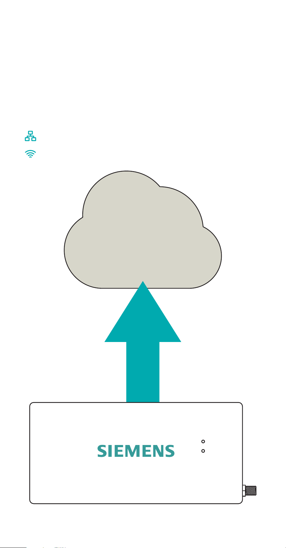
Step 4: Prepare for
Internet connection
The Inhab Energy is capable of connecting to the internet either via a wired LAN
connection, a Wi-Fi connection, or both. If both are implemented, the Inhab Energy
will prioritize wired LAN. If a wired LAN is unavailable, the Inhab Energy will
attempt to connect over Wi-Fi. Choose the preferred method(s) and go to the
corresponding step below.
Step 4(a): Prepare for wired LAN connection
Step 4(b): Prepare for Wi-Fi connection
12 INHAB™ ENERGY INSTALLATION GUIDE
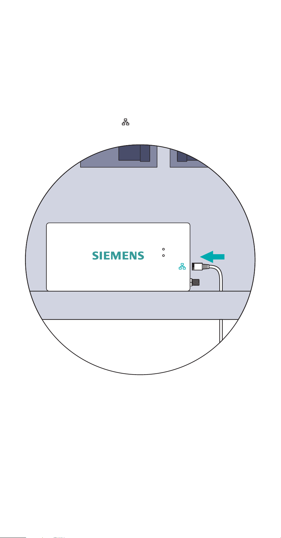
Step 4(a): Prepare for
wired LAN connection
This step is to prepare for a wired internet connection. To connect to the internet
wirelessly via Wi-Fi, see Step 4(b). Run a Cat5e or higher ethernet cable with an
RJ45 connector from a router, switch, or modem to the electrical panel. Then, use a
screwdriver to remove a knockout from the electrical panel. Next, feed the cable
through the hole to the Inhab Energy and plug it in the socket on the right-hand
side of the energy monitor marked .
INHAB™ ENERGY INSTALLATION GUIDE 13
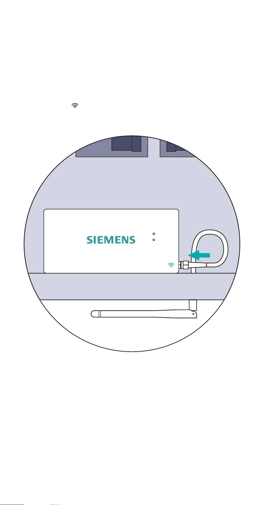
Step 4(b): Prepare for
Wi-Fi connection
This step is to prepare for a wireless internet connection. To connect to the internet
via wired LAN, see Step 4(a). Use a screwdriver to remove a knockout from the
electrical panel. Now, feed the antenna through the hole. Then, screw the antenna
assembly cable to the right-hand side of the energy monitor in the coaxial
connector marked . Finally, plug the hole with the knockout plug. It’s acceptable
to install the antenna inside of a wall.
14 INHAB™ ENERGY INSTALLATION GUIDE
Step 5: Installing Main current
transformers
The Main CTs will attach to the incoming live mains. They should not be used on
neutral lines. They will be installed differently depending upon whether or not the
home has solar and how that solar system is connected to the electrical system. The
Inhab Energy will be installed differently depending on whether the solar is a break-
er-fed or a line-side tap installation. The Main CTs that connect to the mains will
provide net metering out of the box — displaying electricity used minus
electricity produced. These installations are covered in the subsequent pages. To
monitor electricity used and electricity produced separately, Branch CTs will be used
as described in Step 8.
• Step 5(a): No solar Main CT
• Step 5(b): Breaker-fed solar Main CT
• Step 5(c): Line-side tap solar Main CT
Note for Canadian Market: If a service entrance barrier is installed, it may be
necessary to temporarily remove barrier to install Main CTs.
DANGER
Hazardous Voltage
Will cause death or serious injury.
Turn off and lock out all power supplying this device before working on
this device. Replace all covers before power supplying this device is
turned on.
INHAB™ ENERGY INSTALLATION GUIDE 15
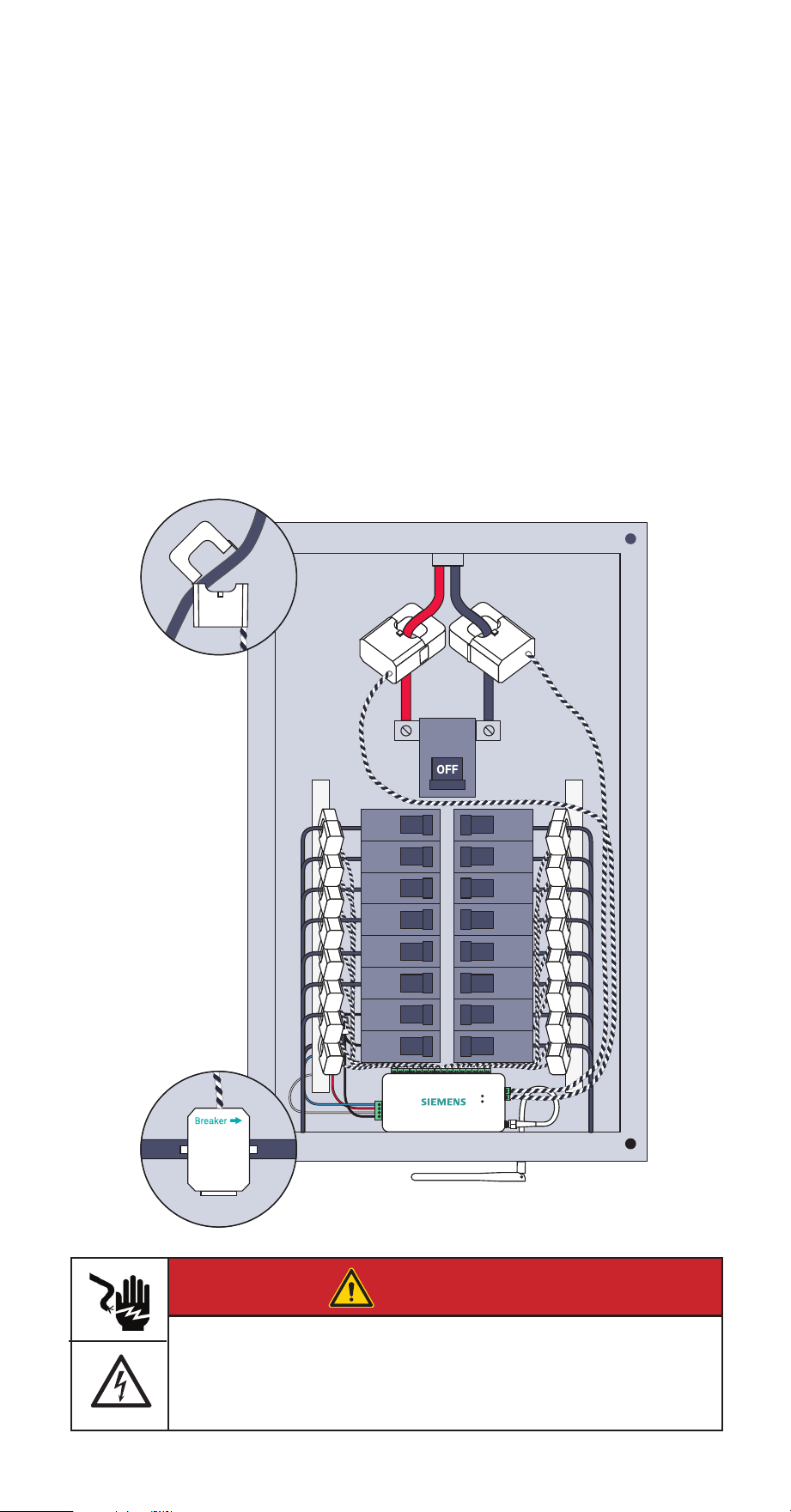
Step 5(a): No solar
Main CT installation
Open the clasps on the CTs and place each clamp around one of the main service
cables. Then, shut the clasps to secure the CTs. IMPORTANT! The Breaker W
imprint on the bottom of CTs should point toward the main breaker or main
lugs installed in the electrical panel. Finally, insert the screw terminal plugs into
the ports on the right side of the monitor. To avoid clutter, unscrew the 22 AWG
wires from the screw terminals, cut them to size, and reattach them ensuring the
black and white wires match the icons on the front of the Inhab Energy.
Breakers
Meter
16 INHAB™ ENERGY INSTALLATION GUIDE
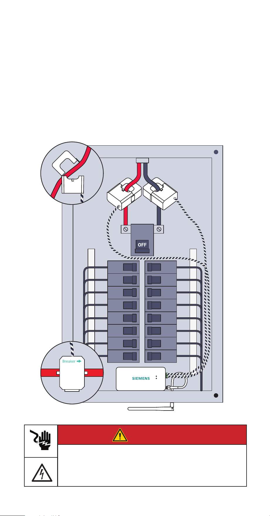
Step 5(b): Breaker-fed solar
Main CT installation
Open the clasps on the CTs and place each clamp around one of the main service
cables between the meter and the main breaker. Then, shut the clasps to secure the
CTs. IMPORTANT! The Breaker W imprint on the bottom of CTs should point
toward the main breaker or main lugs installed in the electrical panel. Finally,
insert the screw terminal plugs into the ports on the right side of the monitor. To
avoid clutter, unscrew the 22 AWG wires from the screw terminals, cut them to size,
and reattach them ensuring the black and white wires match the icons on the front
of the Inhab Energy.
front of the Inhab Energy
Inverter
Solar Panels
Breakers
Meter
DANGER
Hazardous Voltage
Will cause death or serious injury.
Turn off and lock out all power supplying this device before working on
this device. Replace all covers before power supplying this device is
turned on.
INHAB™ ENERGY INSTALLATION GUIDE 17
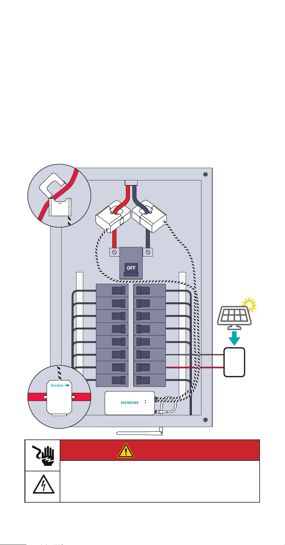
Step 5(c): Line-side tap solar
Main CT installation
Open the clasps on the CTs and place each clamp around one of the main service
cables between the utility meter and incoming line-side inverter taps. Then, shut
the clasps to secure the CTs. IMPORTANT! The Breaker W imprint on the bottom
of CTs should point toward the main breaker or main lugs installed in the
electrical panel. Finally, insert the screw terminal plugs into the ports on the right
side of the monitor. To avoid clutter, unscrew the 22 AWG wires from the screw
terminals, cut them to size, and reattach them ensuring the black and white wires
match the icons on the front of the Inhab Energy.
Inverter
Solar Panels
Breakers
Meter
DANGER
Hazardous Voltage
Will cause death or serious injury.
Turn off and lock out all power supplying this device before working on
this device. Replace all covers before power supplying this device is
turned on.
18 INHAB™ ENERGY INSTALLATION GUIDE
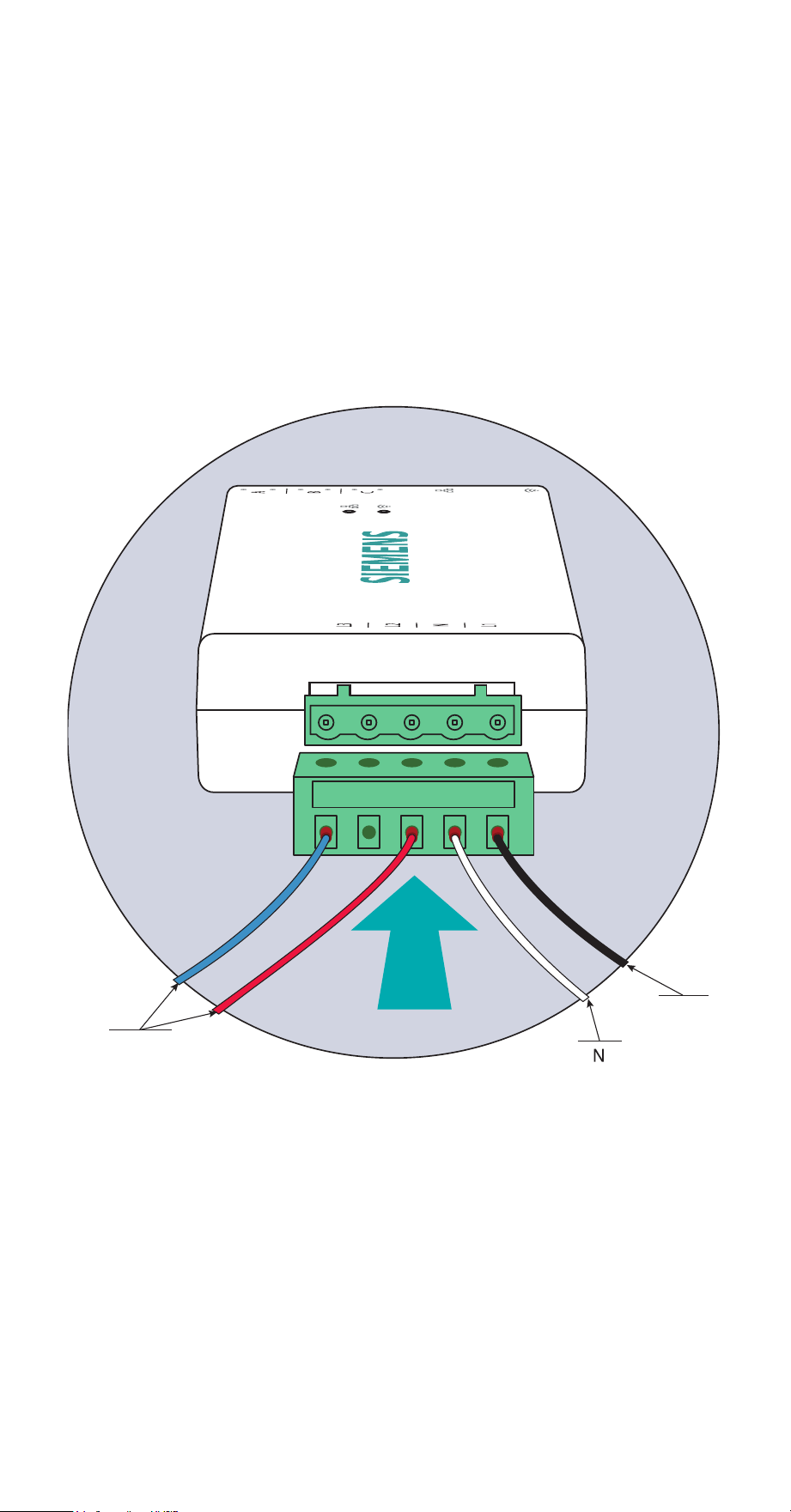
Step 6: Plug in the
voltage sensing wire harness
Insert the 7.6mm screw terminal plug of the power supply wiring harness with four
16 AWG wire leads into the port of the left side of the energy monitor until it clicks
into place securely. These wires can also be cut to length to reduce panel clutter.
The wire harness allows for single-phase power and three-phase voltage sensing:
Black (L1) provides power and voltage sensing, White (N) connects to Neutral, and
Red (L2) and Blue (L3) provide voltage sensing only (if applicable).
L2 & L3
voltage
or neutral
N
neutral
L1
power &
voltage
INHAB™ ENERGY INSTALLATION GUIDE 19
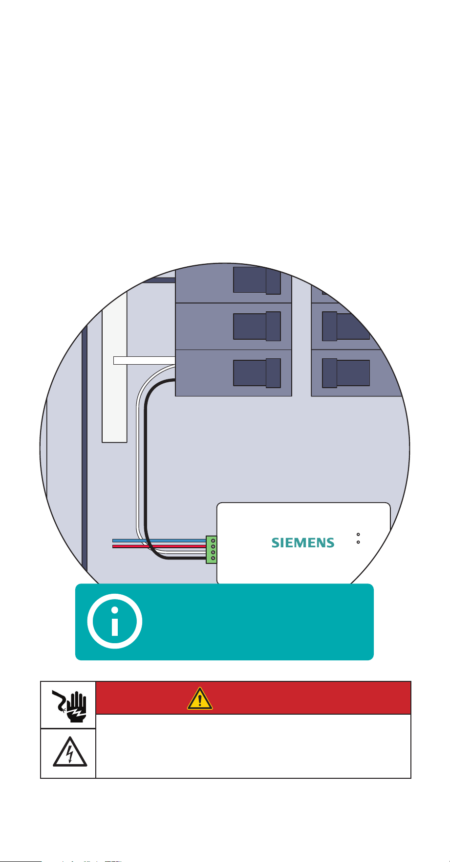
Step 7: Connect the wire harness
The wire harness is wired to one or more breakers in the electric panel.
1. Wiring to an empty breaker
If wiring to an empty (unused) breaker, wire it directly to the breaker.
Follow breaker manufacturer’s instructions for breaker wiring connections.
2. Wiring to a AFCI / GFCI breaker
If the wire harness is connected to an AFCI / GFCI breaker, the black wire
needs to be wired to the breaker load lug and the white wire may need to be
wired to the breaker neutral lug depending on breaker brand and model.
Follow breaker manufacturer’s instructions for breaker wiring connections.
AFCI /
GFCI
N
Breaker
Pigtail
Typical wiring of white and black harness wires
for AFCI/GFCI breakers. Always consult breaker
manufacturer instructions for correct breaker wiring.
DANGER
Hazardous Voltage
Will cause death or serious injury.
Turn off and lock out all power supplying this device before working on
this device. Replace all covers before power supplying this device is
turned on.

20 INHAB™ ENERGY INSTALLATION GUIDE
Step 7 (continued): Connect
the wire harness
The voltage sensing wire harness will be connected differently depending on the
number of Main CTs installed in Step 5. Go to the step below based on the system. It
is recommended to use dedicated breakers for voltage sensing wire connections. If
you’re unsure, contact Siemens Support and we’ll help you through it.
Step 7(a) Common in split phase homes
• Two empty breakers
• Two Main CTs
Step 7(b) Common in 3-phase commercial systems
• Three empty breakers
• Three Main CTs
INHAB™ ENERGY INSTALLATION GUIDE 21
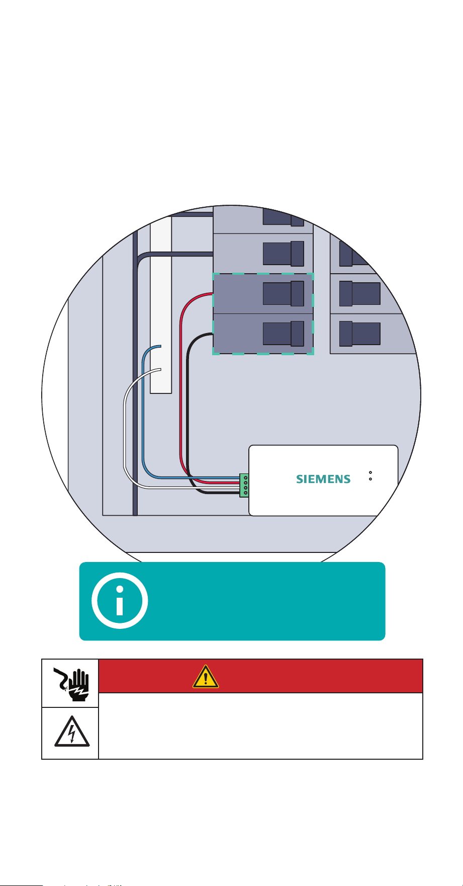
Step 7(a): Two empty breakers
and two Main CTs
Common in split phase homes
Secure the White (N) and Blue (L3) wires from the wire harness to the neutral bus
bar. Turn off breakers in two vertically adjacent (stacked) load center spaces and
secure the Black (L1) and Red (L2) wires from the harness to each breaker terminal.
Use maximum 15A circuit breaker
Adjacent Spaces
DANGER
Hazardous Voltage
Will cause death or serious injury.
Turn off and lock out all power supplying this device before working on
this device. Replace all covers before power supplying this device is
turned on.
22 INHABIT™ ENERGY INSTALLATION GUIDE INHAB™ ENERGY INSTALLATION GUIDE 22
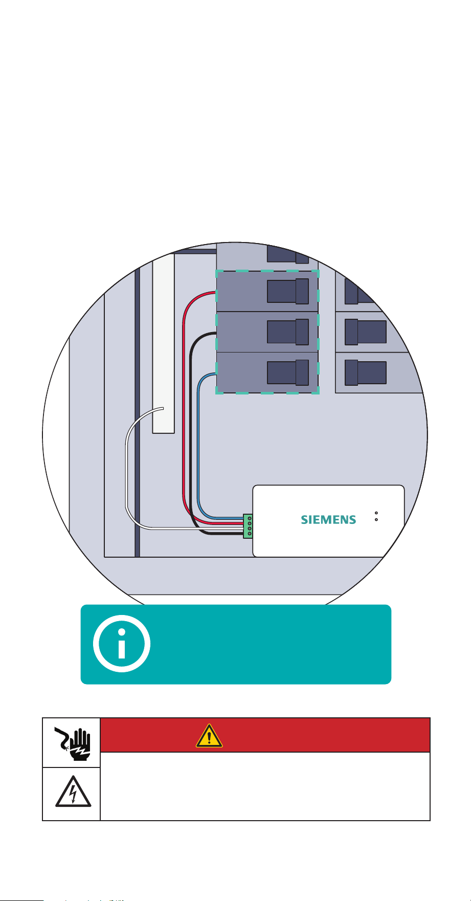
Step 7(b): Three empty
breakers and three Main CTs
Common in 3-phase commercial systems
Secure the White (N) wire from the wire harness to the neutral bus bar. Turn off
breakers in three vertically adjacent (stacked) load center spaces and secure the
Black (L1), Red (L2), and Blue (L3) wires from the harness to each breaker terminal.
Use maximum 15A circuit breaker
Adjacent Spaces
DANGER
Hazardous Voltage
Will cause death or serious injury.
Turn off and lock out all power supplying this device before working on
this device. Replace all covers before power supplying this device is
turned on.
INHAB™ ENERGY INSTALLATION GUIDE 23
Step 8: Plug in and connect the
Branch current transformers
If the Inhab Energy has Branch CTs, open the clasps on the CTs and place each clamp
around the non-neutral leg from the breaker that is to be monitored. Then shut the
clasps to secure the CTs. Then, insert the screw terminal plugs into the ports on the
top of the energy monitor. Note the circuit each CT is installed on and the port where
CT is plugged into the energy monitor, this information will be needed later in the
installation process for app setup. To avoid clutter, unscrew the 22 AWG wires from the
screw terminals, cut them to size, and reattach them ensuring the black and white
wires match the icons on the top of the Inhab Energy.
Note: Make sure that the Breaker W imprint on the bottom of the CTs is pointing
towards the branch breakers.
Branch
Breaker
Load
DANGER
Hazardous Voltage
Will cause death or serious injury.
Turn off and lock out all power supplying this device before working on
this device. Replace all covers before power supplying this device is
turned on.
24 INHAB™ ENERGY INSTALLATION GUIDE
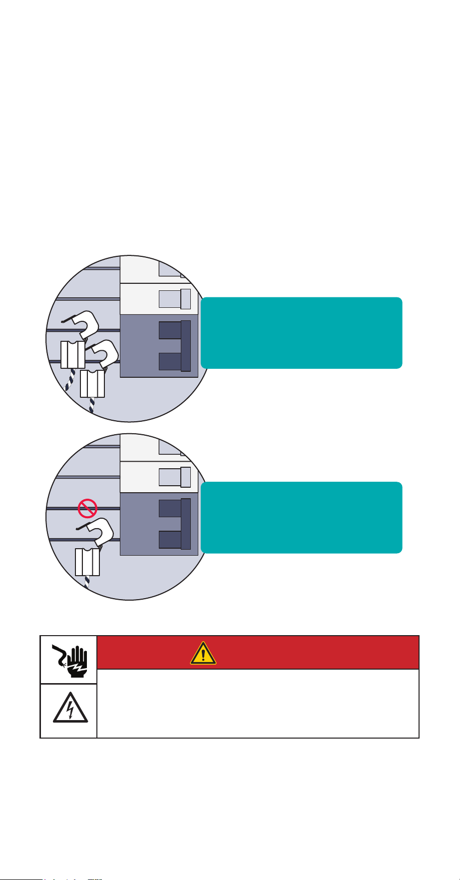
Step 8 (continued): A note
about multi-pole breakers
If 2- or 3-pole breakers are to be monitored, we recommended that one CT be used
for on each pole; however, to conserve the number of CTs, a single CT can be used.
To use a single CT, clasp the clamp around either one of the non-neutral leads
coming off the breaker (it doesn’t matter which). When only one CT is used, input a
circuit multiplier in the app to double or triple the reading by entering a “2” or “3”.
Using a single CT to monitor a multi-pole breaker does not accurately monitor
unbalanced loads.
Most accurate - Attach one
branch sensor on each leg of
the breaker
Less accurate - Attach one
branch sensor on a single leg
and use an app multipler.
DANGER
Hazardous Voltage
Will cause death or serious injury.
Turn off and lock out all power supplying this device before working on
this device. Replace all covers before power supplying this device is
turned on.
INHAB™ ENERGY INSTALLATION GUIDE 25
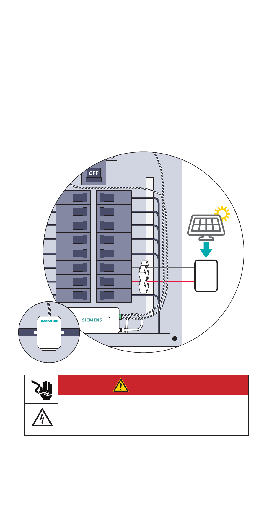
Step 8 (continued):
A note about solar monitoring
For the Inhab Energy to be able to calculate how much energy from the system is
going to and from the grid, Branch CTs will need to be connected to the incoming
leads from the inverter regardless of whether the solar is a breaker-fed or a line-side
tap installation. CTs installation orientation is reversed for solar wires therefore
the Breaker W imprint on the bottom of the CTs should point towards the solar
inverter. Specify the circuits monitored by these CTs as ‘ Solar/Generation’ in the
app. If only one CT is used, input a circuit multiplier in the app to double or triple
the reading by entering a “2” or “3”.
Inverter
Solar Panels
Solar
Load
Center
DANGER
Hazardous Voltage
Will cause death or serious injury.
Turn off and lock out all power supplying this device before working on
this device. Replace all covers before power supplying this device is
turned on.
26 INHAB™ ENERGY INSTALLATION GUIDE
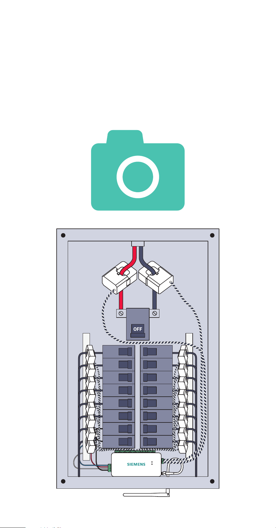
Step 9: Take a photo
of your system
Before replacing your panel cover, take photos of the installation in case you need
to contact support.
Reminder: Make sure you have noted the circuit each CT is installed on and the
port where CT is plugged into the energy monitor. This information will be
needed for app setup.
INHAB™ ENERGY INSTALLATION GUIDE 27
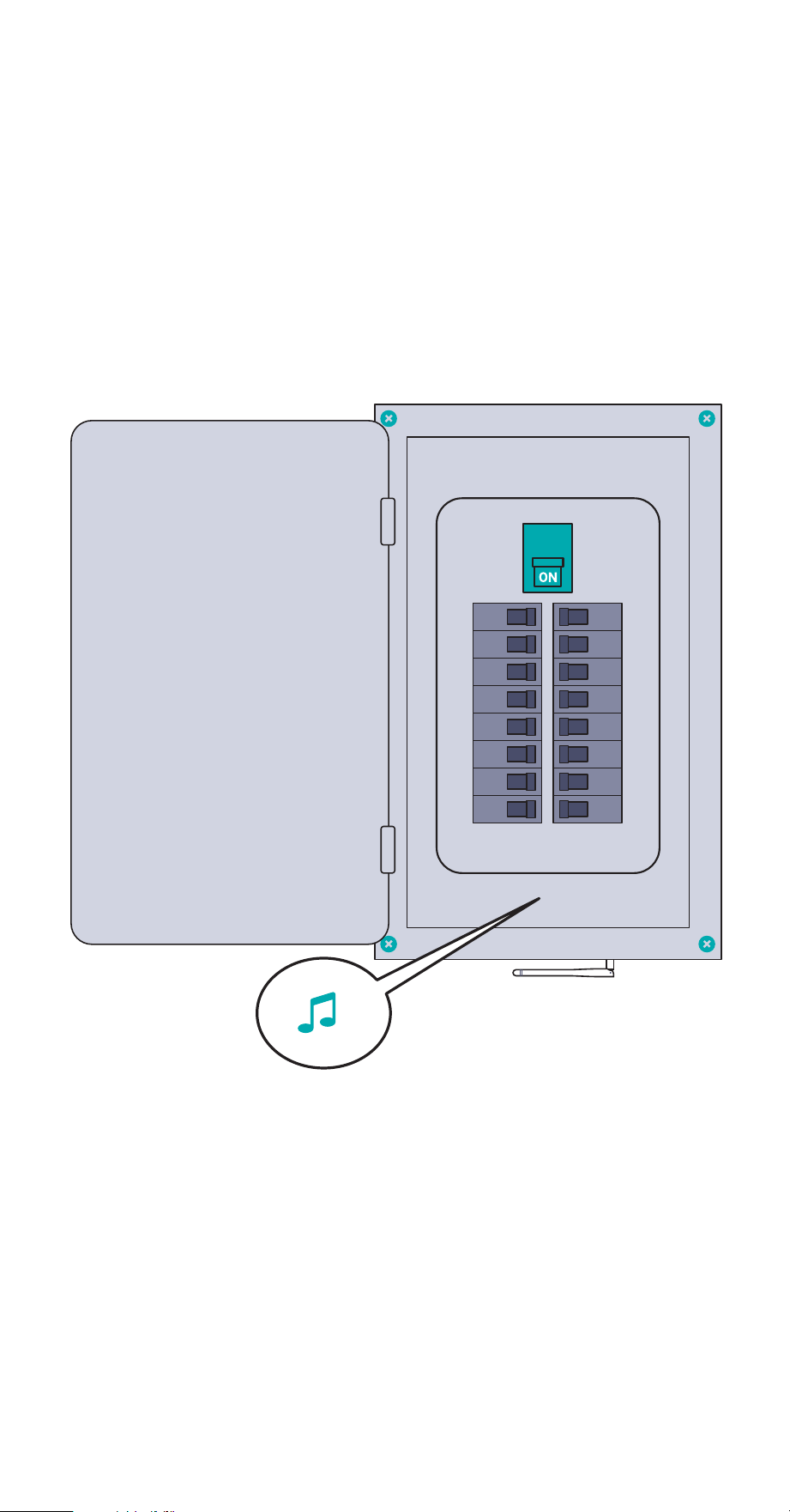
Step 10: Replace the cover
and turn on all breakers
Secure the cover to the box with any screws you removed in Step 2. Next, return any
breakers to the on position that you moved to the off position during installation to
restore power to the circuits in the home. You should hear a power up tone from
the Inhab Energy to confirm it has power. Then, close the panel. Once the panel
cover is replaced, the antenna connector and screw terminal ports on the Inhab
Energy will not be accessible.

28 INHAB™ ENERGY INSTALLATION GUIDE
Step 11: Complete setup
Return to the Siemens Inhab Energy app to continue the setup process that you
began in Step 1 by scanning the QR code on the Inhab Energy or Getting Started
Guide to connect the Inhab Energy to the internet via Wi-Fi or wired LAN
connection.

INHAB™ ENERGY INSTALLATION GUIDE 29
Troubleshooting Tips
Here are some of our most frequent troubleshooting tips. For more help, call the
Siemens Technical Support number at 1-800-241-4453.
The Siemens app is not finding the Inhab Energy after I’ve installed it.
• Ensure the Inhab Energy has power:
- Check for a flashing Wi-Fi light.
- Listen for a startup tone.
- Check the wire harness is secure and wired properly.
- Check that the main breaker is turned on.
- Check that the breaker powering the Inhab Energy is turned on.
• Ensure your phone connect to the Inhab Energy.
- Check your phone’s Bluetooth is on.
- If you’re using an Android, turn on Location Services for your phone to
properly scan for Bluetooth devices.
- If you’re using an iPhone, make sure Bluetooth is allowed in the Settings >
Siemens Inhab Energy app > Bluetooth allowed
• Ensure the Inhab Energy’s Wi-Fi antenna has been installed properly.
- Check the antenna is properly screwed into the energy monitor
- Ensure the antenna is outside of the electric panel. It’s ok if it is inside a wall,
just ensure it’s not inside the metal box.
• Ensure the Inhab Energy’s wired LAN connection is installed properly
- Check that the ethernet cable is securely connected to the Inhab Energy’s
LAN port
- Check that the ethernet cable is securely connected to a router, switch, or
modem
- Ensure the network does not have a firewall preventing new devices from
accessing the internet
• Try power cycling the breaker to which the Inhab Energy is connected.
• Try restarting the Siemens App.
• Try rebooting your phone.
The Siemens Inhab Energy app isn’t getting real-time data from the Inhab
Energy
• Ensure all current transformers are securely fastened around their respective
cables in the electric panel.
• Check the screw terminal plugs are securely plugged into the ports of the
energy monitor.
• Check that the CT wires are securely connected to the screw terminals and that
the screws are tight

30 INHAB™ ENERGY INSTALLATION GUIDE
Troubleshooting Tips
The Siemens app isn’t showing solar net metering or grid measurements from
the Inhab Energy.
• Ensure the Main CTs are clamped on the mains between the meter and
incoming leads from the solar inverter.
• Ensure all CTs are oriented as per the instructions. CTs are directional.
• Check that the appropriate wiring harness wires are attached to adjacent
breakers on different phases
• When configuring the Inhab Energy with the App, make sure that you
temporarily turn the solar off so it is not supplying power to the system. Try
running the configuration at night.
• When configuring the Inhab Energy with the App, make sure that there is a
discernible load on the system. Try turning on an oven, A/C, or dryer.

INHAB™ ENERGY INSTALLATION GUIDE 31
Inhab Energy LED lights
The Inhab Energy has two LED lights on the front of the energy monitor, that can
help troubleshoot the status of the internet connection and whether or not the
monitor has power.
Wi-Fi (and indication of power)
Slowly Flashing Green Not connected to router.
Quickly Flashing Green Connected to router. Attempting Internet connection.
Solid green Connected to Internet.
Wired LAN
Off Not connected to router.
Flashing Blue Connected to router. Attempting Internet connection.
Solid Blue Connected to Internet.

32 INHAB™ ENERGY INSTALLATION GUIDE
Technical Details
Energy Monitor (INHEM1216)
Supported system configurations:
• Single phase, 2-wire systems
• Single-split phase, 3-wire systems
• 3-phase, 4-wire Wye systems with earthed (TN or TT) neutral (no-Delta)
• Fuse: 260VAC/0.3A (Fusible resistor: 10E, 1W, 5%, TH)
• Maximum voltage sense range: 264VAC L-N per channel
• Power usage: < 3 Watts
• Wi-Fi: 2.4 GHz IEEE 802.11b/g/n
• Ethernet: 10/100Base-T, IEEE 802.3
• Operating conditions: -40° - 122° F (-40° - 50° C) | 0-80% RH 3,000 meters above
sea level | Indoor | Dry location Pollution Degree 2
Terminals:
• Ethernet: Cat5e, RJ45, 600V insulation required
• WiFi: SMA coaxial cable, 50Ω impedance, 600V insulation required
• Voltage Terminals:
- ~100-240VAC line-to-neutral, 50/60Hz, 41mA, Overvoltage / Measurement
CAT III
- Field terminal torque value: 5Lb-In/0.56Nm 16AWG, UL1015, 600V, 105C copper-
only wiring
• Main Current Transformer Terminals:
- 3.3V, 1mA, Measurement CAT IV
- Field terminal torque value: 5Lb-In/0.56Nm 22AWG, UL1015, 600V, 105C
copper-only wiring
• Branch Current Transformer Terminals:
- 3.3V, 1mA, Measurement CAT III
- Field terminal torque value: 3Lb-In/0.2Nm 22AWG, UL1015, 600V, 105C
copper-only wiring
Main Current Transformers (INHEM010)
• Max Primary Current: 200A
• Max Voltage: 250V (Primary) / 333mV (Secondary)
• Burden Resistor: 5ohm, 1%, 1/4W
• Cable length: 1m
• Inside diameter: 22 mm
• Accuracy: ±2%
Branch Current Transformers (INHEM001)
• Max Primary Current: 50A
• Max Voltage: 250V (Primary) / 333mV (Secondary)
• Burden Resistor: 20ohm, 1%, 1/4W
• Cable length: 1m
• Inside diameter: 10 mm
• Accuracy: ±2%
INHAB™ ENERGY INSTALLATION GUIDE 33
Information de sécurité
AVERTISSEMENT
AVERTISSEMENT indique une situation dangereuse qui, si elle n’est pas
évitée, peut entraîner la mort ou des blessures graves.
Ceci est le symbole d‘alerte de sécurité. Il est utilisé pour vous avertisser
des risques potentiels de blessures corporelles. Respectez tous les
messages de sécurité qui accompagnent ce symbole pour éviter
d‘éventuelles blessures ou la mort.
AVERTISSEMENT
L‘Siemens Inhab Energy nécessite l‘installation de transformateurs à
l‘intérieur du panneau électrique de votre maison et une tension
dangereuse pouvant entraîner des blessures ou la mort. Siemens vous
prions de bien vouloir que l‘installation soit effectuée par une personne
qualifiée, telle qu‘un électricien agréé ou un autre professionnel
qualifié, conformément au code électrique régional du lieu
d‘installation.
Une installation ou une utilisation incorrecte de l‘équipement peut
être dangereuse, voire mortelle. Siemens ne pourra en aucun cas être
tenu responsable envers vous ou un tiers pour tout dommage, direct
ou indirect, pour une blessure personnelle résultant de votre
non-respect des informations et instructions de sécurité contenues
dans ce guide d‘installation.
AVERTISSEMENT
• Coupez l’alimentation du panneau électrique avant l’inspection.
Portez des lunettes et des gants de protection avant de tenter d’in
specter le système Inhab Energy. Assurez-vous qu’aucun câblage
pour la mesure de tension, la mesure de courant, l’alimentation ou
les données n’est eloché ou n’a de conducteurs exposés. Assurez-
vous qu’il n’y a pas de fissures, de cassures ou d’autres défauts dans
le boîtier du Inhab Energy ou des CT.
• Si vous pensez que l’un des composants de l’Siemens Inhab Energy
peut avoir été endommagé, n’essayez pas de l’utiliser. Contactez
immédiatement l’assistance à support@emporiaenergy.com.
• N’utilisez pas l’Siemens Inhab Energy d’une manière autre que
celle spécifiée dans ce guide d’installation, sinon la protection
fournie par l’équipement pourrait être altérée.
• N’essayez pas d’ouvrir, de démonter ou de réparer l’un des
composants de l’Siemens Inhab Energy.
• N’installez pas l’Siemens Inhab Energy dans des environnements
contenant des gaz ou des vapeurs explosifs ; ni dans des environne
ments humides ou mouillés ; ni en plein soleil ; ni lorsque les
températures sont constamment inférieures à -40 °F (-40 °C) ou
supérieures à 122 °F (50 °C).
• Assurez-vous que l’Siemens Inhab Energy n’est pas sous tension
pendant toute manipulation, y compris l’installation et le
démontage.
• N’eectuez aucun entretien, service ou nettoyage du Inhab Energy
après l’installation. Contactez le service client pour obtenir
de l’aide.
• L’Siemens Inhab Energy ne doit être utilisé qu’avec des transforma
teurs de courant de surveillance de l’énergie répertoriés. Isolation
de base, utilisez les TC uniquement sur un conducteur isolé, à
l’abri des contacts avec des pièces sous tension.
• Pour réduire le risque de choc électrique, toujours ouvrir ou décon
necter les circuits du système de distribution d’alimentation (ou de
service) d’un bâtiment avant l’installation ou l’entretien transforma
teurs de courant.
• L’Siemens Inhab Energy doit être câblé à l’aide de fils de cuivre
16AWG, 600V, UL1015, 105° C (ou plus)
• Il est recommandé de câbler l’Siemens Inhab Energy au disjoncteur
le plus proche de l’appareil.
34 INHAB™ ENERGY INSTALLATION GUIDE
Information de sécurité

INHAB™ ENERGY INSTALLATION GUIDE 35
Information de sécurité
AVERTISSEMENT
• Ne placez pas l’Siemens Inhab Energy de manière à ce qu’il soit
dicile d’actionner des dispositifs de déconnexion ou des disjoncteurs.
• N’utilisez pas d’accessoires tiers ou Current Transformateurs (TC)
avec l’Siemens Inhab Energy. Le Inhab Energy et les CT sont
personnalisés et intégrés. Les accessoires tiers ou les TC peuvent
compromettre l’exactitude des données et la sécurité de
l’équipement.
• Les transformateurs de courant ne peuvent pas être installés dans
des équipements où ils dépassent 75 % de l’espace de câblage de
toute section transversale de l’équipement.
• Restreindre l’installation des transformateurs de courant dans une
zone où cela obstruerait les ouvertures de ventilation.
• Restreindre l’installation des transformateurs de courant dans une
zone d’évacuation d’arc du disjoncteur. N’installez pas le moniteur
d’énergie Siemens Inhab Energy dans une zone où les gaz d’échap
pement de la ventilation de l’arc du disjoncteur pourraient être redi
rigés à la suite de l’installation d’un équipement de sous-mesure.
• L’Siemens Inhab Energy n’est pas adapté aux méthodes de câblage
de classe 2 et n’est pas destiné à être connecté à un équipement de
classe 2. (Se référer à NEC 2023, l’article 725.)
• Sécurisez les transformateurs de courant et acheminez les
conducteurs de manière à ce qu’ils n’entrent pas directement en
contact avec les bornes sous tension ou les bus.
• L’Siemens Inhab Energy ne doit pas être monté à moins de 50,8
mm (2 pouces) de toute pièce sous tension, y compris les
conducteurs primaires, les bornes primaires et les cosses primaires ;
mais à l’exclusion des câbles isolés. Il est acceptable que le Inhab
Energy soit monté sur le boîtier du panneau mis à la terre et près
des barres omnibus neutres/terre. Le Inhab Energy utilise un
câblage de classe I permettant à ses fils de coexister en toute
sécurité avec tous les autres fils du panneau.
• Si le moniteur d’énergie Siemens Inhab Energy est fixé au boîtier, il
ne doit pas entrer en contact avec l’isolation intérieure du panneau,
telle que le matériau qui sépare les barres omnibus GND et LIVE.
• Les dispositions de montage du moniteur d’énergie Siemens Inhab
Energy ne doivent être fixées à aucune pièce sous tension.
• Les connexions de détection de tension et d’alimentation électrique
à la tension primaire doivent être protégées contre les surintensités
par le biais d’une connexion à un disjoncteur/MCB.

Measurement categories are defined by the CE and UL safety standard IEC 61010-1
and are used to indicate the ability of an instrument (like the Inhab Energy Monitor)
to withstand voltage spikes without posing a shock hazard to the operator. An
instrument should only be used at or below its rated measurement category and
voltage. For example, the Inhab Energy Monitor is CAT III rated and can be used to
monitor CAT I, CAT II, and CAT III circuits.
CAT III: This category is for measurements performed on equipment permanently
installed in the building. Examples are measurements on motor control centers,
circuit-breaker panels, junction boxes, switches, lighting fixtures, and wiring,
including cables, bus-bars, and equipment for industrial use and some other
equipment, for example, stationary motors with permanent connections to the
electrical distribution system.
There are situations where the Inhab Energy Monitor needs to monitor the main
service entrance, which is classified as CAT IV. In this situation, the Inhab Energy
voltage inputs (green screw terminal block) must be connected in a breaker panel
or panel board, downstream of a the main disconnect, breaker, or fuses. The line
voltages at this location will be essentially identical to the voltages measured at the
main disconnect, so the Inhab Energy’s measurements will be accurate.
This device complies with Industry Canada licence-exempt RSS-247 standard.
Operation is subject to the following two conditions: (1) this device may not cause
interference, and (2) this device must accept any interference, including
interference that may cause undesired operation of the device.
Le présent appareil est conforme aux CNR d’Industrie Canada applicables aux
appareils radio exempts de licence. L’exploitation est autorisée aux deux conditions
suivantes : (1) l’appareil ne doit pas produire de brouillage, et (2) l’utilisateur de
l’appareil doit accepter tout brouillage radioélectrique subi, même si le brouillage
est susceptible d’en compromettre le fonctionnement.
36 INHAB™ ENERGY INSTALLATION GUIDE
Energy Monitor
E527638, E527638, E535044

INHAB™ ENERGY INSTALLATION GUIDE 37
Federal Communication Commission Interference Statement
This equipment has been tested and found to comply with the limits for a Class B
digital device, pursuant to Part 15 of the FCC Rules. These limits are designed to
provide reasonable protection against harmful interference in a residential
installation.
This equipment generates, uses and can radiate radio frequency energy and, if not
installed and used in accordance with the instructions, may cause harmful
interference to radio communications. However, there is no guarantee that
interference will not occur in a particular installation. If this equipment does cause
harmful interference to radio or television reception, which can be determined by
turning the equipment off and on, the user is encouraged to try to correct the
interference by one of the following measures:
• Reorient or relocate the receiving antenna.
• Increase the separation between the equipment and receiver.
• Connect the equipment into an outlet on a circuit different from that to which
the receiver is connected.
• Consult the dealer or an experienced radio/TV technician for help.
FCC Caution: To assure continued compliance, any changes or modifications not
expressly approved by the party responsible for compliance could void the user’s
authority to operate this equipment. (Example - use only shielded interface cables
when connecting to computer or peripheral devices).
This device complies with Part 15 of the FCC Rules. Operation is subject to the
following two conditions:
(1) This device may not cause harmful interference, and (2) This device must accept
any interference received, including interference that may cause undesired operation.
Caution: Any changes or modifications not expressly approved by Siemens void
the user’s authority to operate the equipment.
FCC ID:
2AS6P-EMV3A
Model: EMV3-A

38 INHABIT™ ENERGY INSTALLATION GUIDE
Legal Manufacturer
Siemens Industry, Inc.
3617 Parkway Ln
Peachtree Corners, GA 30092
United States of America
www.usa.siemens.com/InhabEM
Order No. PDIG-INHABEM-0424
This document contains a general description of
available technical options only and its
effectiveness will be subject to specific variables
including field conditions and project
parameters. Siemens does not make
representations, warranties, or assurances as to
the accuracy or completeness of the content
contained herein. Siemens reserves the right to
modify the technology and product specifications
in its sole discretion without advance notice.
© 2024 Siemens Industry, Inc.
Product Support:
Web: usa.siemens.com/InhabEM
Telephone: 1-800-241-4453
Tech Login: usa.siemens.com/InhabEM_tech